Raymond Gofer® 261 High-level Order picker Maintenance Manual 1043938A – PDF DOWNLOAD
Original price was: $78.00.$24.95Current price is: $24.95.
Raymond Gofer® 261 High-level Order picker Maintenance Manual 1043938A – PDF DOWNLOAD
Description
Raymond Gofer® 261 High-level Order picker Maintenance Manual 1043938A – PDF DOWNLOAD
FILE DETAILS:
Raymond Gofer® 261 High-level Order picker Maintenance Manual 1043938A – PDF DOWNLOAD
Language : English
Pages : 322
Downloadable : Yes
File Type : PDF
Size: 11.1 MB
DESCRIPTION:
Raymond Gofer® 261 High-level Order picker Maintenance Manual 1043938A – PDF DOWNLOAD
Manual Design
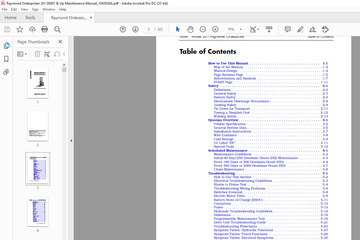
TABLE OF CONTENTS:
Raymond Gofer® 261 High-level Order picker Maintenance Manual 1043938A – PDF DOWNLOAD
How to Use This Manual 1-1
Map of the Manual 1-2
Manual Design 1-4
Page Revision Page 1-5
Abbreviations and Symbols 1-7
START Page 1-11
Safety 2-1
Definitions 2-2
General Safety 2-3
Battery Safety 2-5
Electrostatic Discharge Precautions 2-8
Jacking Safety 2-9
Tie-Down for Transport 2-11
Towing a Disabled Unit 2-12
Welding Safety 2-13
Systems Overview 3-1
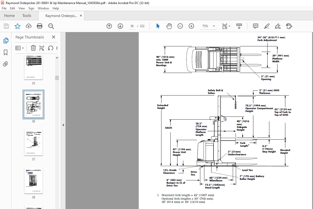
Vehicle Specification 3-2
General System Data 3-5
Installation Instructions 3-7
Wire Guidance 3-8
Cold Storage 3-9
UL Label “EE” 3-11
Special Tools 3-12
Scheduled Maintenance 4-1
Maintenance Guidelines 4-2
Initial 90 Day/250 Deadman Hours (HD) Maintenance 4-3
Every 180 Days or 500 Deadman Hours (HD) 4-4
Every 360 Days or 2000 Deadman Hours (HD) 4-7
Chain Maintenance 4-8
Troubleshooting 5-1
How to Use This Section 5-2
Electrical Troubleshooting Guidelines 5-3
Shorts to Frame Test 5-4
Troubleshooting Wiring Problems 5-6
Switches (General) 5-8
Electric Motor Tests 5-9
Battery State-of-Charge (BSOC) 5-11
Contactors 5-13
Fuses 5-13
Hydraulic Troubleshooting Guidelines 5-14
Definitions 5-15
Programmable Maintenance Tool 5-16
Drive Unit Troubleshooting Guide 5-21
Troubleshooting Flowcharts 5-23
Symptom Tables: Hydraulic Functions 5-27
Symptom Tables: Travel Functions 5-29
Symptom Tables: Electrical Symptoms 5-30
Codes and Tests 6-1
Operator Display Messages 6-2
Table of Contents Gofer® Model 261 High-level Orderpicker
ii Publication Number: 1043938A, Issued: 31 August 2006
Maintenance Mode 6-4
Traction Power Amplifier Fault Codes 6-7
Operator Display Fault Codes 6-15
Component Procedures 7-1
List of Component Procedures 7-2
Component Locator Photos 7-5
Covers and Finish 7-11
Decals 7-11
Steering and Controls 7-13
Operator Display 7-14
Steering Wheel 7-15
Steer Encoder 7-16
Control Handle 7-17
Throttle Potentiometer 7-18
Drive and Brake 7-19
Drive Unit 7-20
Drive Wheel 7-22
Brake 7-24
Electrical Components 7-27
Battery Procedures 7-28
Motors (General) 7-31
Drive Motor 7-35
Lift Motor 7-37
Steer Motor 7-38
Traction Power Amplifier 7-40
Contactors 7-41
Contactor Tip Replacement 7-43
Fuses 7-45
Circuit Cards (General) 7-46
Switches (General) 7-47
Hydraulic Components 7-51
Hydraulic Manifold 7-52
Hydraulic Reservoir 7-53
Hydraulic Fluid 7-54
Solenoid Valves 7-55
Lift Pump 7-56
Lift Pressure Relief Valve Adjustment 7-57
Bleeding the Hydraulic System 7-58
Side Cylinder 7-59
Center Cylinder 7-63
Flow Control Valve 7-65
Mast Section 7-67
Three-Stage Carriage 7-68
Inner Telescopic 7-72
Outer Telescopic 7-74
Two-Stage Carriage 7-75
Two-Stage Telescopic 7-77
Mast Bearings 7-78
Mast Disassembly and Shimming 7-80
Lift Chains, Three-Stage 7-84
Lift Chains, Two-Stage 7-86
Forks 7-87
Pallet Clamp 7-88
Load Wheels 7-89
Skid Pads 7-90
Theory of Operation 8-1
Battery Plugged In 8-2
Key Switch (S1) ON 8-3
Closing Deadman Switches 8-5
Travel 8-6
Lift/Lower 8-9
Primary Memory 8-13
Pinout Matrix 8-15
Wire Guidance 9-1
System Overview 9-2
Set-Up Procedure 9-3
Codes and Tests 9-6
Tests 9-28
General Troubleshooting 9-30
Troubleshooting in FlashWare 9-31
Theory of Operation 9-33
Firmware Configuration 10-1
FlashWare Program 10-2
Appendix A-1
Lubrication Specification Chart A-2
Torque Chart – Standard (Ferrous) A-3
Torque Chart – Standard (Brass) A-4
Torque Chart – Metric A-5
Decimal Equivalent Chart A-6
Standard/Metric Conversions A-8
Electrical Schematics B-1
Hydraulic Schematic B-8
IMAGES PREVIEW OF THE MANUAL:
Customer Support: [email protected]
PLEASE NOTE:
- This is the SAME exact manual used by your dealers to fix your vehicle.
- The same can be yours in the next 2-3 mins as you will be directed to the download page immediately after paying for the manual.
- Any queries / doubts regarding your purchase, please feel free to contact [email protected]
S.M