
Renault Midlum DXI Electrical Workshop Manual 2006 (Doc 70 152) – PDF Download
Original price was: $52.95.$34.95Current price is: $34.95.
Complete electrical workshop manual for Renault Midlum DXI trucks (2006), covering CAN BUS architecture, wiring diagrams, distribution box, connectors, available power supplies and pinpointing of appliances. Doc 70 152.
Description
Renault Midlum DXI Electrical Workshop Manual — Document 70 152
This is the complete electrical workshop manual for the Renault Midlum DXI range, published under document number 70 152 and dated 06/2006. It covers the full electrical architecture of the vehicle: CAN BUS networks, wiring diagrams, distribution box layouts, connector pinouts, available power supplies, chassis-cab connections, trailer sockets, and the pinpointing of individual appliances. Everything is presented in the same sequence a technician would follow when tracing a fault, from overall system architecture down to individual terminal numbers and wire colours.
File Details
- Manual type: Electrical Workshop Manual
- Brand: Renault Trucks
- Model: Midlum DXI
- Document number: 70 152
- Date: 06/2006
- Language: English (GB)
- Page count: 296 pages
- File format: PDF
Chapters Covered
- Generalities
- CAN BUS architecture
- Electrical diagram
- Pinpointing of appliances
- Electrical distribution
- Distribution box
- Chassis – cab / bulkhead grommet
- Trailer sockets
- Available power supplies
- Connectors
- Dashboard wiring harness
Generalities
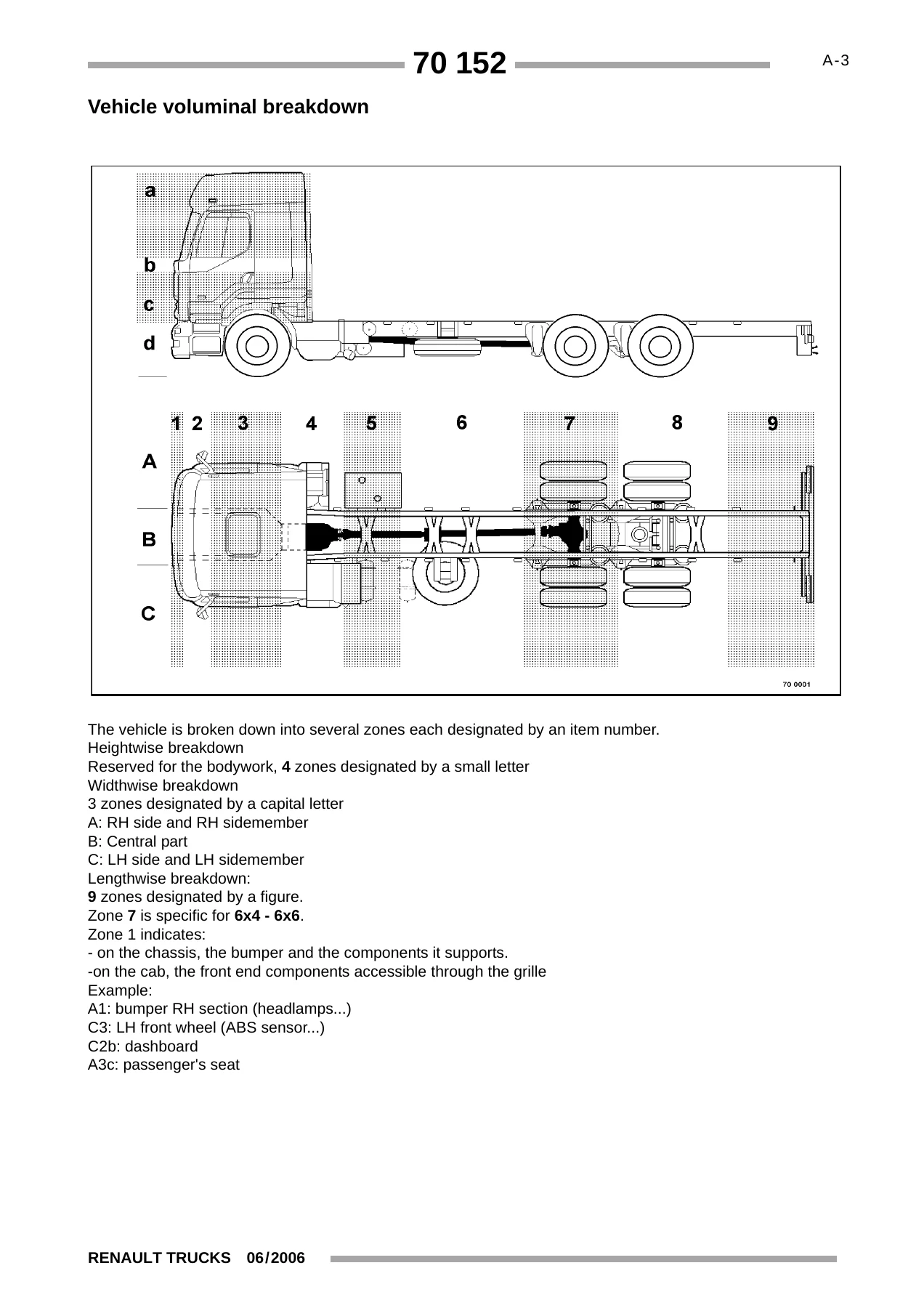
Covers the conventions used throughout the manual: how to read the diagrams, definition of an illustration, cross-references, appliance identification, fuses and relays, polarities, and graphic conventions. Includes the vehicle voluminal breakdown (lengthwise, widthwise and heightwise zones) used to locate components, plus warnings and safety instructions for working on the electrical system. This section also explains the colour code applicable to connectors and wires, and precautions to take when making electrical measurement readings on electronic appliances.
CAN BUS Architecture
Details the vehicle’s CAN BUS network topology, including J1587-1, J1939-1, J1939-2 and J1939-ENG feedback zones. Each feedback zone plate is accompanied by a key to appliances listing the ECUs and sensors connected to that bus, with cross-references to the relevant diagram plates. The section also includes notes on variants and options such as automatic vs manual transmission, air suspension configurations, and retarder types. This is the reference for understanding how the various electronic control units communicate and how to diagnose bus-related faults.
Electrical Diagram
This is the largest section of the manual and contains the complete electrical schematics for the vehicle. It includes energy production (both standard and ADR configurations), control ECU ADR, electrical distribution (seven plates), air production management, lighting and signalling management, windscreen wipers and headlamp wash, side/marker/identification/parking lights, rear lights, headlights and front lights, specific trade lights and horn, front door electric window winders and sun-roof, rear door electric window winders, swivelling defrosting rearview mirrors, comfort lighting, comfort accessories, radio/CB radio/telephone, air conditioning, independent heating, diff. lock, EBS braking system, gearbox, air suspension, electric retarder, hydraulic retarder, vehicle electronic management, engine electronic management, urea inflow management, alarm, doors/engine immobilizer controls, tachograph, diagnostic socket, main information display, trailer sockets, available power supplies, and onboard management. Each diagram plate shows wire numbers, connector references, fuse/relay references and pin numbers.
Pinpointing of Appliances
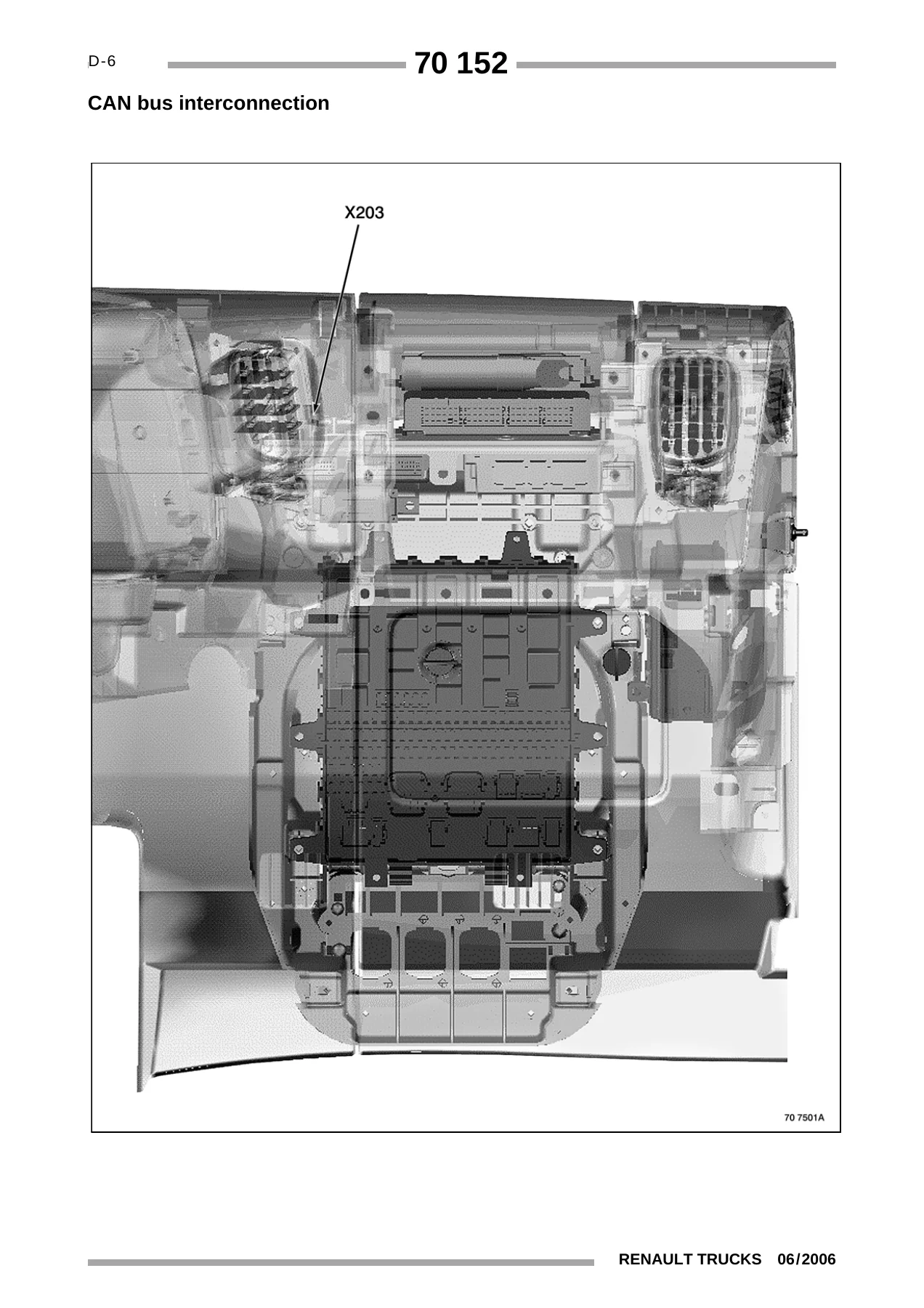
Provides the location of every electrical and electronic appliance on the vehicle, referenced to the voluminal breakdown zones. The section includes photographs and illustrations showing the physical position of components on the dashboard, engine, chassis, and body. It covers the distribution box, CAN bus interconnection, vehicle electronic management, urea inflow management, engine electronic management for both DXi 5 and DXi 7 engines, engine appliance layouts, electric retarder, air suspension, EBS equipment, electronic anti-theft, alarm, lighting and signalling management, doors management, fuses and relays outside the distribution box, bodybuilders’ equipment and pre-arrangements, and earths. Each appliance is listed with its code, function name and location reference.
Electrical Distribution
Details the cab electrical distribution box, chassis-cab connection, and bulkhead grommet. Includes the distribution box connector faces A and B with connector item numbers, function names, colours and number of ways. Also covers the chassis-cab connection connectors (XT02, XT12, XT13, XT14, XT22, XT32, XT33, XT42, XT53, XT54, XT55, XT56, XT62, XT63, XT70) and their functions. The trailer socket section covers the 15-pin type and the 7-pin EBS type with pin assignments and fuse references.
Available Power Supplies
Lists all available power supplies provided by Renault Trucks for bodybuilders and auxiliary equipment, with polarity numbers and fuse references. Locations covered include PB1, PB2, PB3, PB4, PB5 and the cab/chassis connection area. The section includes strict warnings about not tapping into existing wiring harnesses, using only approved connectors, adapting cable sections to the required use, and never changing fuse ratings.
Connectors
Provides the dashboard wiring harness connector data across 15 sub-sections. Lists each connector code, function, connector designation, colour and number of tracks. This includes connectors for the principal information display, radio set, air suspension ECU, vehicle management ECU, EBS braking management ECU, lighting and signalling management ECU, hydraulic and electric retarder ECUs, FMS-GATEWAY management ECU, gear selector ECU, accelerator pedal sensor unit, steering wheel fingertip controls, and many more. This section is essential for anyone tracing wires or replacing connectors.
What This Manual Covers in Detail
The Renault Midlum DXI electrical workshop manual covers the complete electrical system of the vehicle, including every circuit from battery to component. It documents the CAN BUS communication networks (J1587-1, J1939-1, J1939-2 and J1939-ENG) with full feedback zone diagrams. It includes the electrical distribution box with fuse and relay tables, showing amperage ratings and diagram page references. The manual covers the EBS braking system across five diagram plates, including the EBS table for 4×2 and 4×4 configurations. It documents both the DXi 5 and DXi 7 engine electronic management systems, including sensors, actuators, injector solenoid valves, and the urea inflow management system. It covers air suspension configurations for 4×2 (<18T) with electronic rear air suspension and integral electronic air suspension, and 4×2 (≥18T) with integral electronic air suspension. It also documents the electric and hydraulic retarder systems, the alarm system, the electronic anti-theft system, the tachograph, and the diagnostic sockets.
Who This Manual Is For
This Renault Midlum DXI workshop manual is intended for technicians, mechanics and electricians working on Renault Midlum DXI vehicles. It is also useful for fleet maintenance managers, bodybuilders, and anyone who needs to understand the electrical architecture of these trucks. The level of detail — down to individual wire numbers, connector terminal numbers, and colour codes — makes it suitable for both diagnostic work and complete harness repairs. The manual is written in English and follows the standard Renault Trucks documentation format.
Why This Manual Matters
Electrical faults on modern commercial vehicles can be difficult to trace without the correct diagrams. The Renault Midlum DXI electrical manual provides the exact wire numbers, connector references, and pin assignments needed to diagnose faults accurately. It shows how each circuit is protected, where fuses and relays are located, and how the various ECUs communicate over the CAN BUS networks. Without this information, technicians risk incorrect repairs, damaged ECUs, or unnecessary component replacement. With the manual, you can follow a logical diagnostic path from the symptom to the faulty circuit, saving time and avoiding guesswork.
IMAGES PREVIEW
Instant PDF Delivery
This Renault Midlum DXI electrical workshop manual is delivered as an instant PDF download after payment. There is no shipping, no waiting, and no physical media. You can access the manual immediately on any device — laptop, tablet, or smartphone — and print the pages you need for use in the workshop. The PDF format allows you to zoom in on complex diagrams, search for specific wire numbers or component codes, and keep the manual on file for future reference. Whether you are working on a single vehicle or maintaining a fleet, this manual gives you the electrical information you need, when you need it.
Reviews
There are no reviews yet.