
Renault Trucks C & D Wide Wiring Diagrams Manual 337003/15 – 2019 PDF Download
Original price was: $79.95.$49.95Current price is: $49.95.
Complete 592-page Renault Trucks C & D Wide wiring diagrams manual (doc 337003/15, 2/2019). Full CAN bus architecture, engine management, EBS, suspension, lighting, fuse/relay tables, connector pinouts and harness routing for 4×2, 6×2, 6×4 and 8×4 TRIDEM configurations.
Description
Renault Trucks C & D Wide Wiring Diagrams Manual – 337003/15
This is the complete electrical wiring diagrams manual for Renault Trucks C & D Wide vehicles, document number 337003/15, published 2/2019. At 592 pages, it delivers the full electrical architecture for the C and D Wide range across 4×2, 6×2, 6×4 and 8×4 TRIDEM configurations, covering 8-litre, 11-litre and Cummins gas engines in Euro VI Phase 1 (OBDEP-A), Phase 2 (OBDEP-C) and Phase 3 (OBDEP-D) variants. Everything is diagram-first: CAN bus layout, ECU pinouts, fuse and relay assignments, connector face views, harness routing and system-by-system circuit diagrams.
File Details
- Manual type: Wiring Diagrams Manual
- Brand: Renault Trucks
- Model: C & D Wide
- Document number: 337003/15
- Edition/date: 2/2019
- Language: English (with multilingual information notices in French, Italian, Spanish, Hungarian, Finnish, Czech, Danish, German, Dutch, Polish, Portuguese, Russian and Turkish)
- Page count: 592
- File format: PDF
Chapters Covered
The manual is organised into functional groups, each with dedicated diagram sheets, device keys and connector references. The top-level sections are:
- Communication Bus Architecture
- Energy Production and Distribution
- Vehicle Starting
- Vehicle Management
- Engine Management
- Gearbox Management
- Driveline Management
- Retarder Management
- Braking Management
- Suspension Management
- Controlled Axle Management
- Air Production Management
- Safety Management
- Lighting and Signalling
- Windscreen Washing and Wiping
- Rear Viewing
- Driving Assist
- Life on Board
- Vehicle Maintenance
- Trailer Connections
- Body Builder System Management
- Electrical Distribution (Fuses, Relays, Diodes)
- Available Power Supplies
- Wiring Harnesses
- Cab and Chassis Inter-connectors
- Layout of Controls
Communication Bus Architecture and CAN Networks
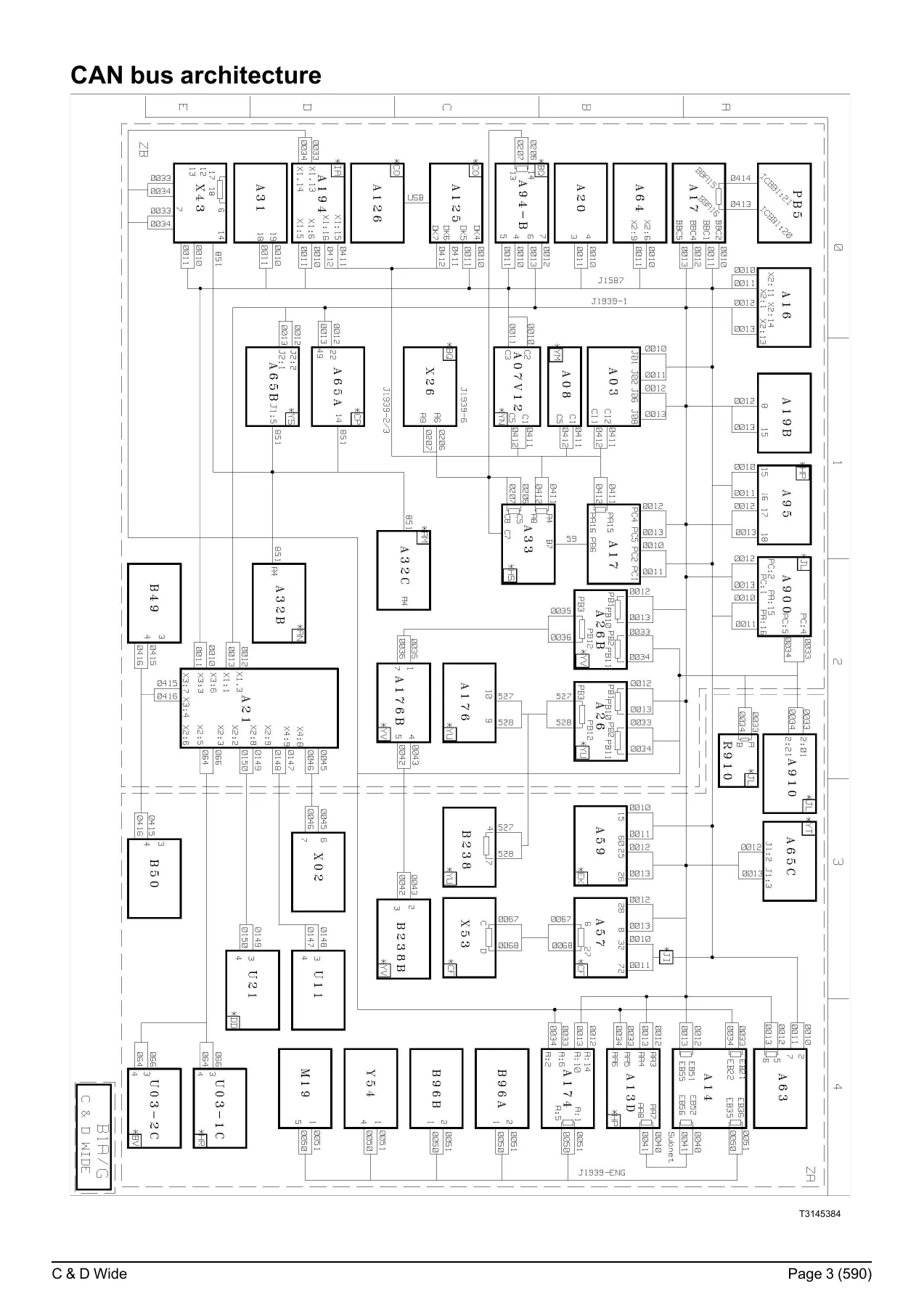
The opening section maps the complete CAN bus topology for the C & D Wide range, including the J1587-1, J1939-1, J1939-2, J1939-ENG and J2284 main bus transfer zones. It identifies every ECU on the network — engine, gearbox, EBS, air suspension, immobiliser, tachograph, body builder pre-equipment, telematics gateways and more — with bus termination resistors and gateway interfaces. This is the section you need when diagnosing communication faults or integrating additional electronic modules.
Energy Production and Distribution
Covers the complete power supply chain from batteries and master switch through to the fuse and relay box. Includes standard and ADR energy production diagrams, the full internal circuit of the EJB distribution box split across eight sheets, fuse and relay tables for both diesel and gas vehicles, diode tables, external fuses and relays, and the face A and face B connector pinout charts for the electrical distribution box. Every fuse rating, relay coil connection and connector pin assignment is documented.
Engine Management and Emissions Control
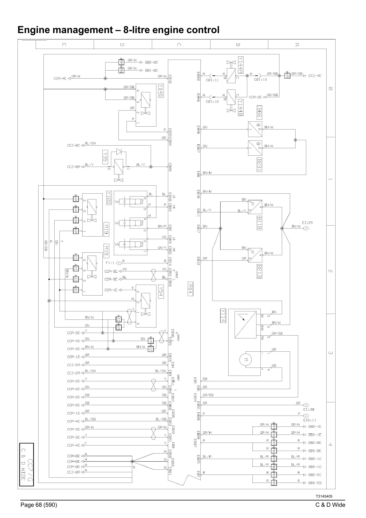
Dedicated diagram sets for 8-litre, 11-litre and Cummins gas engines across Euro VI Phase 1, Phase 2 and Phase 3. Covers engine ECU pinouts, injector solenoid valves, common rail pressure sensors, EGR valves, turbocharger control, exhaust brakes, VTC engine brake, lambda sensors, NOx sensors, DPF pressure sensors, urea dosing and ACM control. Includes engine harness routing diagrams, engine earth points and the interface connectors between engine and vehicle harnesses.
Gearbox, Driveline and Retarder Management
Circuit diagrams and connector references for ALLISON generation 4 and generation 5 automatic gearboxes, OPTIDRIVER automated manual transmission, and manual gearboxes with hydraulic retarder. Includes gear selector control units, clutch position sensors, output speed sensors, power take-off solenoids, and the complete range of retarder systems: electric retarder (pre-04/12/2017 and post-03/12/2017 TELMA iRCS), hydraulic retarder and VOITH hydraulic retarder. Differential lock circuits for 4×2, 6×2, 6×4 and 8×4 TRIDEM drivelines are also covered.
Braking, Suspension and Axle Management
The EBS section covers all options across 4×2, 6×2, 6×4 and 8×4 TRIDEM vehicles, including the EBS ECU, brake pedal position sensor, wheel speed sensors, brake lining wear sensors, ABS solenoid valves and trailer control modules. Suspension management spans 4×2 full air, 6×2 TAG, 6×4 and 8×4 TRIDEM air suspension with height sensors, pressure sensors, solenoid valve assemblies and the ECS control unit. Controlled axle management covers the RASEC ECU and steered axle angle sensors. Air production management and the APM control unit are also documented.
Cab, Safety and Body Builder Systems
Central door locking, immobiliser, alarm system and tachograph circuits are detailed with their respective control units and antenna connections. Body builder system management covers the PB1 through PB5 pre-equipment connectors, the body builder pre-equipment management control unit (A17), available power supply points, and the interface between vehicle and body builder systems. Air conditioning, independent heating, radio and comfort accessories are included in the life-on-board sections.
Lighting, Signalling and Auxiliary Systems
Complete external and internal lighting management: main beam, dipped beam, fog lights, daytime running lights, direction indicators, side marker lights, parking lights, brake lights, reversing lamps, beacons and work spotlights. Includes the lighting and signalling management control unit, steering wheel fingertip controls, headlamp height adjustment motors, windscreen wiper and washer circuits, electric rear-view mirrors and horn circuits.
Electrical Distribution, Connectors and Harness Routing
The final sections provide the full fuse and relay tables for the EJB electrical distribution box with amperage ratings, folio references and circuit descriptions. Connector face views for all major harness interfaces — XCBB, XCH, XCI, XCIC, XCIO, XCIF, XCIG, XCIM, XCIN, XCIR, XCIS, XFB, XFD, XFF, XFL, XFRC, XFTP, YCF, YFB, YFD, YFF, YFL, YFS, YFR, YFRA, YFSA, YFT, YFTP — are documented pin-by-pin. Harness routing diagrams show the physical path of each harness through the cab and chassis, and the trailer socket pinouts for 7-pin ABS/EBS and 15-pin configurations complete the electrical picture.
Why This Wiring Diagrams Manual Matters
Electrical faults on modern commercial vehicles are rarely solved by guesswork. The Renault Trucks C & D Wide wiring diagrams manual gives you the exact circuit path, connector pinout, fuse rating and relay logic for every system on the vehicle. Whether you are tracing an intermittent CAN bus fault, replacing a body builder interface connector, diagnosing an EBS warning, integrating a new body on the chassis, or repairing a lighting circuit, the relevant diagram is here. The fuse and relay tables alone save hours of probing — every circuit is listed with its protection rating and diagram folio reference.
IMAGES PREVIEW
Instant PDF Delivery
This Renault Trucks C & D Wide wiring diagrams manual is delivered as an instant PDF download after payment — no shipping, no waiting. It is printable and viewable on any device, from a workshop tablet to a laptop in the cab. Keep the complete 592-page electrical reference for the C and D Wide range on hand for every diagnostic and repair job.
Reviews
There are no reviews yet.