
Renault Premium DXi 11 Euro 3 Electrical Manual – Wiring Diagrams & ECU Diagnostics PDF
Original price was: $59.95.$39.95Current price is: $39.95.
Complete electrical manual for Renault Premium DXi 11 Euro 3 trucks. 256 pages of wiring diagrams, CAN bus architecture, ECU pinouts, fuse tables, component locations, and bodybuilder power supplies. Instant PDF download.
Description
This is the complete electrical manual for the Renault Premium DXi 11 Euro 3 truck range, published by Renault Trucks in August 2005 under reference 70 149 and document number 50 21 024 188. It covers the electrical system from the battery and alternator through to the CAN bus gateways, EBS braking, air suspension, retarder, tachograph, and bodybuilder connections. Every wiring diagram, connector pinout, fuse table, and component location for the 4×2, 6×2, and 6×4 variants is included.
File Details
- Manual type: Electrical Manual (Electrics)
- Brand: Renault Trucks
- Model: Renault Premium DXi 11 Euro 3
- Language: English (GB)
- Page count: 256
- File format: PDF
- Document number: 50 21 024 188
- Reference: 70 149
- Date: 08/2005
Chapters Covered
- Generalities (A-1 to A-8)
- CAN BUS architecture (B-1 to B-5)
- Electrical diagram (C-1 to C-141)
- Pinpointing of appliances (D-1 to D-65)
- Electrical distribution (E-1)
- Distribution box (E1-2 to E1-18)
- Trailer sockets (F-1 to F-3)
- Available power supplies (G-1 to G-8)
- Dealer Network and Customer Follow-up (H-1 to H-2)
Generalities (A-1 to A-8)
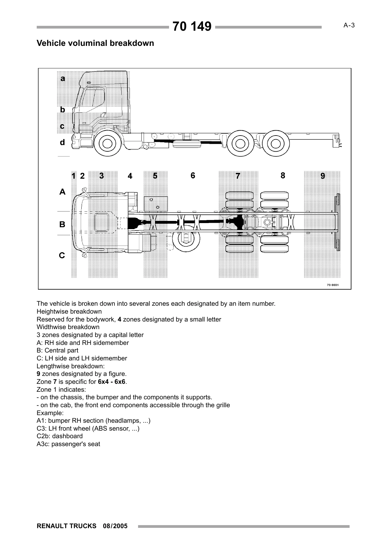
The opening chapter sets up the framework for everything that follows. It includes the vehicle voluminal breakdown that divides the truck into numbered zones (A1 through C9) so every connector, sensor, and module has a precise location reference. It explains the folio system used throughout the wiring diagrams — how to read cross-references, appliance coding, fuse and relay identification, polarity numbering, and graphic conventions. Wiring harness connector presentations, the colour code table for wires and connectors, and the precautions to observe when taking electrical measurements are all covered here. Read this chapter before diving into the diagrams.
CAN BUS Architecture (B-1 to B-5)
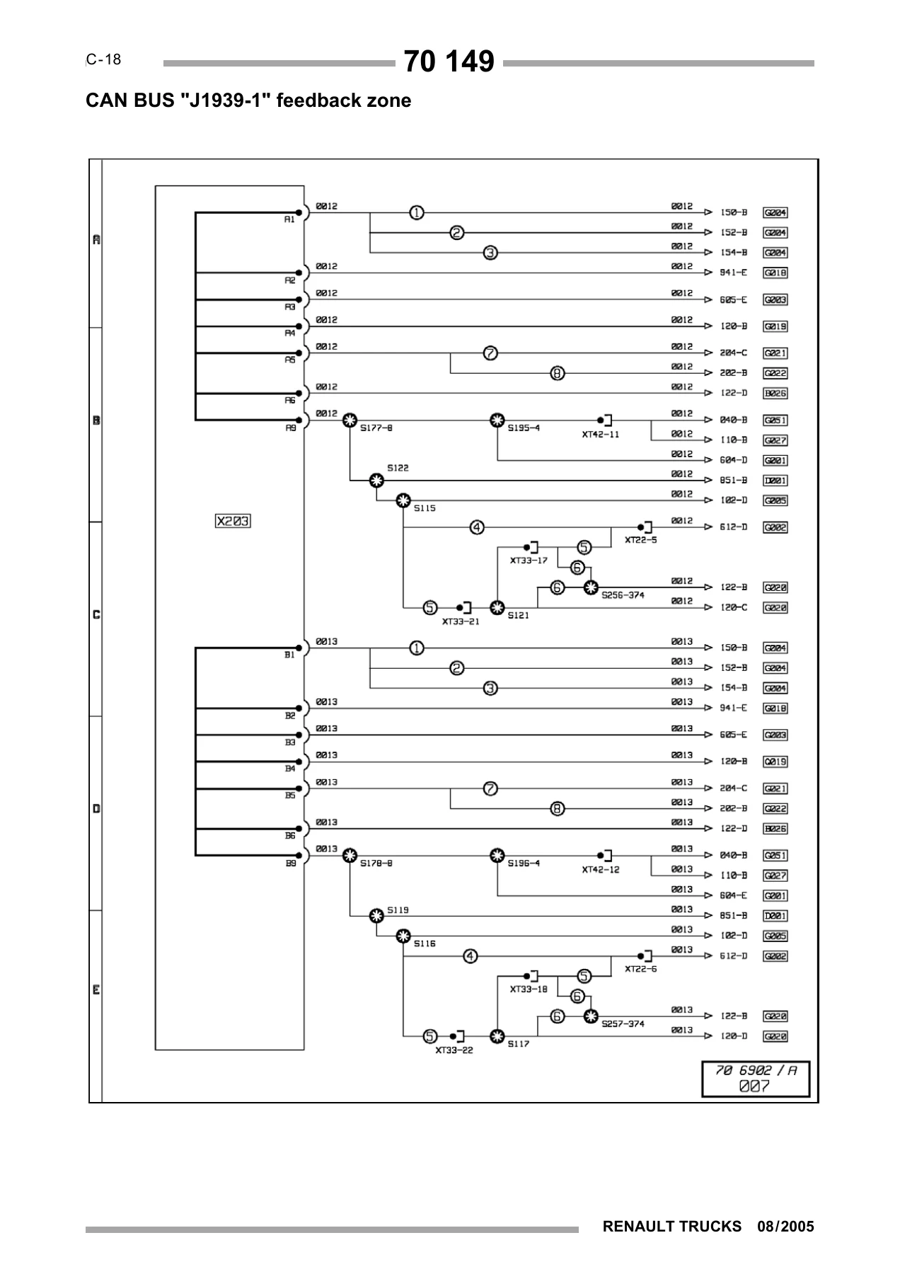
Two separate appliance keys are provided: one for vehicles with manual gearbox and one for automatic transmission. Each lists ECU codes, function names, and physical locations (A2b, B3b, C2c, etc.) for every module on the network. The CAN BUS J1587-1, J1939-1, and J1939-2 feedback zones are laid out in full diagram form, showing how the vehicle management ECU, engine management ECU, EBS, air suspension, retarder, tachograph, and diagnostic sockets communicate. Variant notes explain which components apply to which suspension, gearbox, and axle configuration.
Electrical Diagram (C-1 to C-141)
The core of the manual and by far the largest chapter. It contains the complete electrical schematics for the vehicle, broken into numbered diagram plates. Coverage includes energy production (standard and ADR), electrical distribution (seven plates), air production management, lighting and signalling management, windscreen wipers and headlamp wash, side/marker/identification and parking lights, rear lights, headlights and front lights, specific trade lights and horn, electric window raisers, swivelling defrosting rearview mirrors, comfort lighting, comfort accessories, radio/CB/telephone, air conditioning, independent add-on heating (AT2000 ST, Therme 90S, and AT2000 ST ADR variants), differential lock, the full EBS braking system (seven plates including EBS tables for 4×2/4×4, 6×2/6×4, and 8×2/8×4), piloted axle, automatic transmission, gearbox ALLISON 3000V, electronic air suspension for 4×2 tractors and other configurations, hydraulic and electric retarders, vehicle electronic management, bodybuilder pre-arrangement management, engine electronic management, alarm, doors/engine immobilizer controls, tachograph, diagnostic socket, main information display, trailer sockets, available power supplies, and onboard management (FMS + TMC / FMS + RAL).
Pinpointing of Appliances (D-1 to D-65)
This chapter gives the physical location of every electrical and electronic component on the vehicle. It includes the distribution box, CAN bus interconnection, vehicle electronic management, engine electronic management for the DXi11 (manual and automatic), layout of appliances on the DXi11 engine, hydraulic retarder, air suspension layouts for 4×2, 6×2 TAG, and 6×2 PUSHER configurations, EBS equipment layouts for 4×2, 6×2 TAG, and 6×2 PUSHER, automatic transmission, electronic anti-theft, alarm, lighting and signalling management, doors management, fuses and relays outside the distribution box, bodybuilders’ equipment and pre-arrangements, and earths. Photographs and technical illustrations show exactly where each component sits on the cab, chassis, and engine.
Electrical Distribution and Distribution Box (E-1, E1-2 to E1-18)
The electrical distribution chapter introduces the cab distribution box, which houses the majority of the vehicle’s fuses and relays. The distribution box chapter then provides the full fuse and relay tables: every entry gives the function name, folio reference, fuse or relay item number, and amperage. Connector face A is detailed with connector item numbers, function names, colour codes, and number of ways. This is the reference section for tracing power supply faults and identifying which fuse protects which circuit.
Trailer Sockets (F-1 to F-3)
Pinout tables for the 15-pin trailer socket and the 7-pin EBS trailer socket. Each pin is listed with its function and the fuse that protects it. Essential for diagnosing trailer lighting, ABS/EBS communication, and power supply faults.
Available Power Supplies (G-1 to G-8)
Documents the bodybuilder connection points and available power supplies at each location (PB1, PB2, PB3, PB5, etc.). Each entry gives the function name, polarity number, fuse item, and amperage. Also includes the rules for making electrical connections to the vehicle — mandatory use of approved connectors, cable section recommendations (7 Amps per mm²), and the prohibition on changing fuse ratings. Critical for anyone installing bodybuilder equipment or auxiliary systems.
Dealer Network and Customer Follow-up (H-1 to H-2)
Contact information and a feedback form for reporting divergences between the manual and the vehicle.
Who This Manual Is For
This Renault Premium DXi 11 Euro 3 electrical manual is written for technicians, auto electricians, fleet maintenance workshops, and bodybuilders who work on these trucks. It covers the 4×2, 6×2, and 6×4 variants listed on the cover, with manual and automatic transmission options. The diagnostic content — CAN bus architecture, ECU pinouts, wiring diagrams, and component locations — supports fault-finding on everything from a non-starting engine to an EBS warning light, a faulty tachograph signal, or a trailer socket that won’t power up.
Why This Manual Matters
Electrical faults on a modern truck can come from anywhere: a chafed wire in the chassis harness, a corroded connector at the distribution box, a failed sensor on the engine, a CAN bus communication error, or a bodybuilder installation that tapped into the wrong circuit. Without the wiring diagrams and component locations, every diagnosis is a guess. With this manual, you can trace the circuit from the battery to the component, check the correct fuse or relay, verify the pinout at the connector, and read the CAN bus topology to understand how the ECUs talk to each other. The pinpointing chapter tells you exactly where each sensor and module is physically located, so you spend less time searching and more time fixing.
IMAGES PREVIEW
Instant PDF Delivery — No Waiting
The complete Renault Premium DXi 11 Euro 3 electrical manual is delivered as a PDF immediately after payment. No shipping, no waiting for a disc or a printed book. Open it on a laptop in the workshop, a tablet on the pit, or print the pages you need for the job. Every diagram, table, and photograph is exactly as Renault Trucks published it in 08/2005 — the same reference material used by the dealer network, now on your screen in seconds.
Reviews
There are no reviews yet.