
Renault Premium DXi 11 Euro 4 & DXi 7 Electrical Workshop Manual – Doc 70 154 (2006)
Original price was: $59.95.$39.95Current price is: $39.95.
Complete electrical workshop manual for Renault Premium DXi 11 Euro 4 and DXi 7 trucks. Document 70 154, edition 06/2006. Covers CAN bus architecture, full electrical diagrams, appliance pinpointing, distribution box, trailer sockets, available power supplies and more. Instant PDF download.
Description
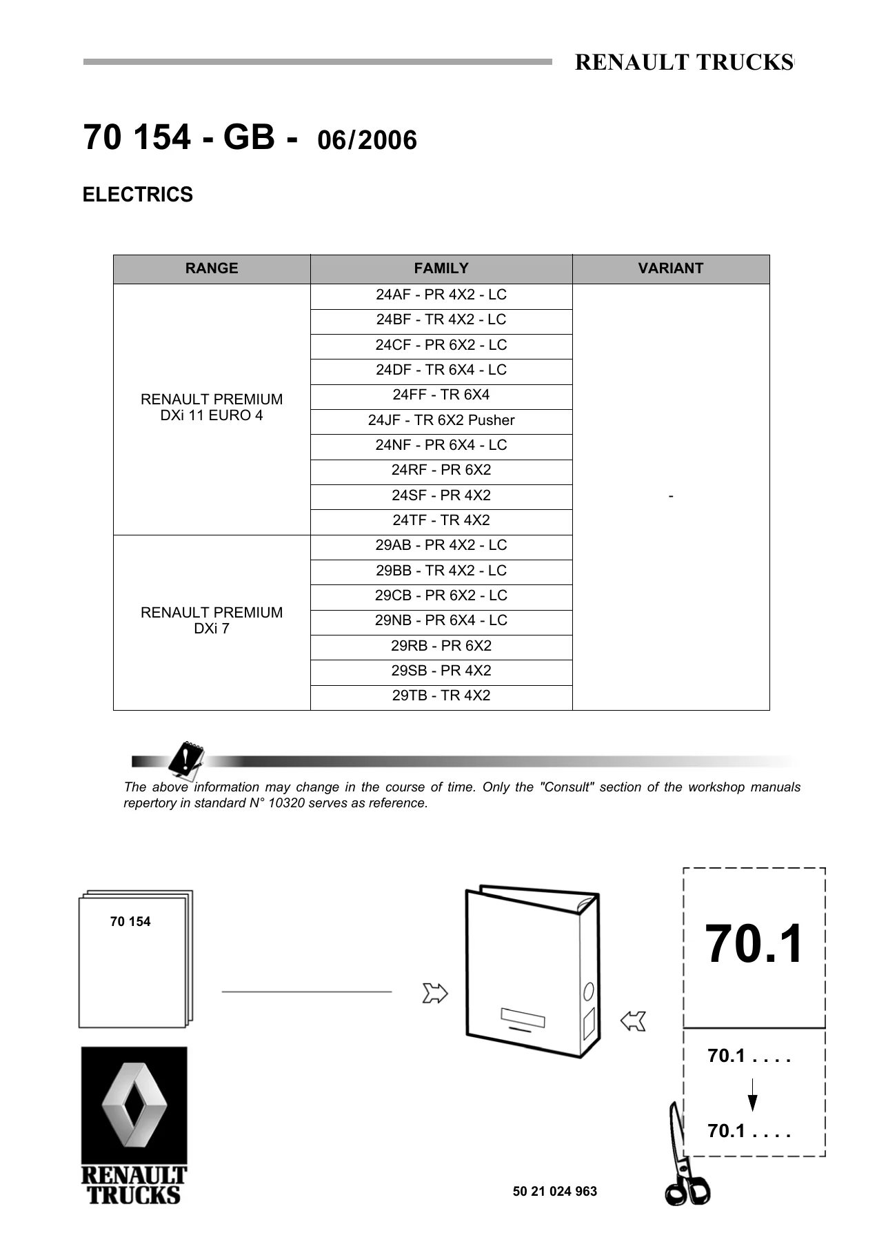
Renault Premium DXi 11 Euro 4 & DXi 7 Electrical Workshop Manual — Document 70 154
This Renault Trucks electrical workshop manual (document number 70 154, edition 06/2006) is the complete electrical reference for the Renault Premium DXi 11 Euro 4 and Renault Premium DXi 7 truck ranges. It covers the full electrical architecture — from CAN bus network feedback zones and energy production circuits to distribution box layouts, appliance pinpointing, trailer sockets, and the complete electrical wiring diagram set. Whether you are diagnosing a fault on a Premium DXi 11 Euro 4 tractor or tracing a wiring issue on a DXi 7 rigid, this manual gives you the diagrams, codes, and connector data you need.
File Details
- Manual type: Electrical workshop manual
- Brand: Renault Trucks
- Models covered: Renault Premium DXi 11 Euro 4, Renault Premium DXi 7
- Document number: 70 154
- Edition/date: 06/2006
- Language: English (GB)
- Page count: 286
- File format: PDF
Chapters Covered
- Generalities
- CAN BUS architecture
- Electrical diagram
- Pinpointing of appliances
- Electrical distribution
- Distribution box
- Chassis – cab / bulkhead grommet
- Trailer sockets
- Available power supplies
- Dealer Network and Customer Follow-up
Generalities
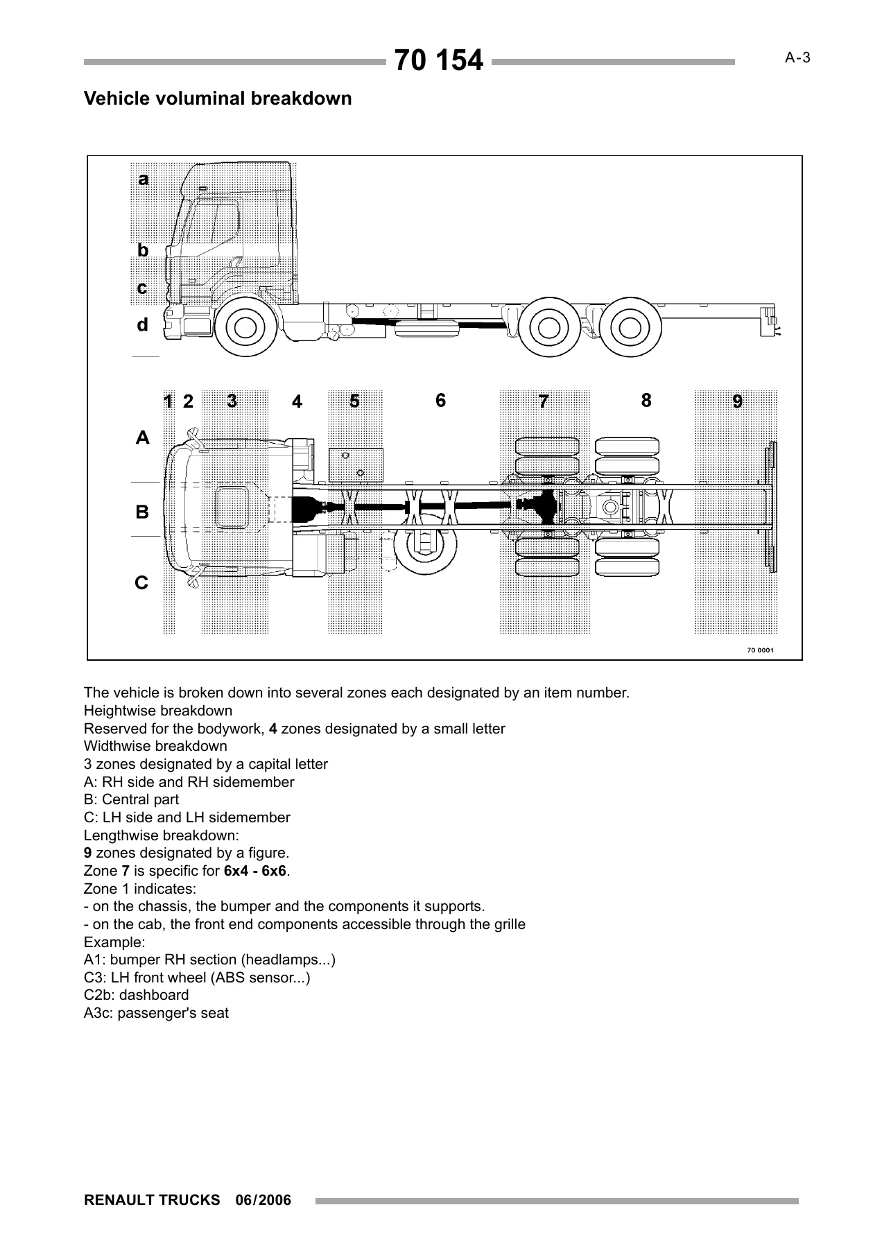
This opening chapter explains how to read the Renault electrical diagrams, defines the symbols used for appliances, relays, fuses and polarities, and lays out the graphic conventions that govern every diagram in the manual. It also breaks the vehicle down into height, width and length zones (A/B/C and 1–9) so that component locations can be pinpointed precisely, and it sets out the precautions required when taking electrical measurements on these trucks — including the warning against using test lamps on electronic appliances and the requirement to use a digital or needle-type multimeter.
CAN BUS Architecture
The CAN bus chapters document the vehicle’s data network feedback zones: J1587-1, J1939-1, J1939-2, and J1939-ENG. Each zone is presented as a full-page diagram showing how the ECUs and connectors communicate across the network, along with a key to appliances and notes on variants such as manual versus automatic transmission, 4×2 versus 6×2 suspension, DXi 7 versus DXi 11 engines, hydraulic versus electric retarder, and with or without onboard management.
Electrical Diagram
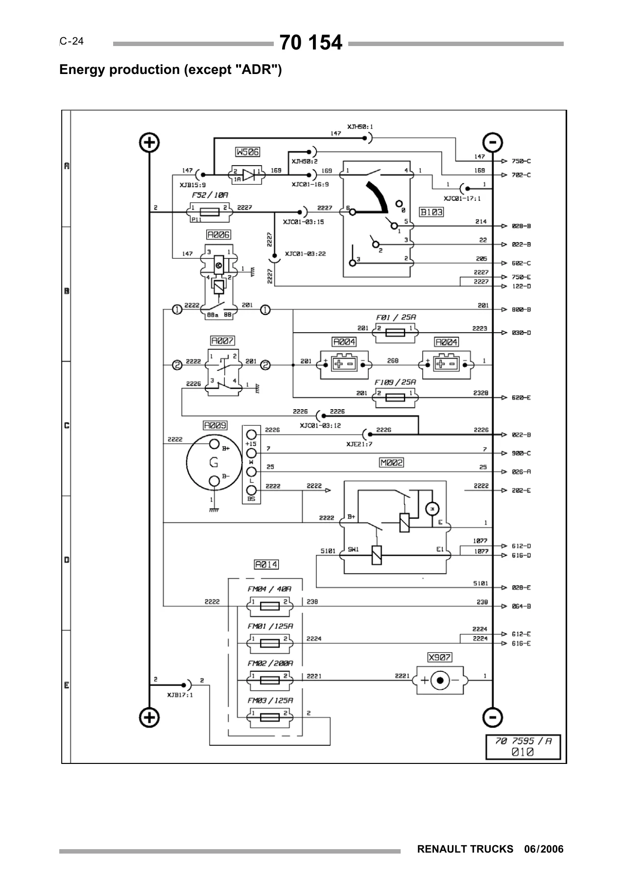
At the core of this manual is the complete electrical diagram set — 149 folios covering everything from energy production (standard and ADR), electrical distribution 1/7 through 7/7, air production management, lighting and signalling, wipers and washer, side/marker/parking lights, rear lights, headlights and front lights, trade lights and horn, electric windows and sunroof, rear-view mirrors, comfort lighting, radio and CB, air conditioning, independent heating (AT2000 ST and Thermo 90S), diff locks, EBS braking, piloted axle, automatic transmission, electronic air suspension, electric and hydraulic retarders, vehicle electronic management, engine management for both DXi 11 and DXi 7, urea inflow management, alarm, door locking, immobilizer, tachograph, diagnostic socket, main information display, trailer sockets, available power supplies, and onboard FMS management.
The EBS braking system alone spans seven folios covering 4×2, 6×2, and 8×2/8×4 configurations with dedicated EBS tables. Engine electronic management is split across DXi 11 (1/2 and 2/2) and DXi 7 (1/2 and 2/2), covering sensors, injectors, engine brakes, and aftertreatment. Air suspension has dedicated diagrams for 4×2 tractors, non-4×2 tractors, and 6×2 configurations.
Pinpointing of Appliances
This 73-page section lists every appliance on the vehicle by its after-sales code number, function name, and location. Codes range from A001 (cab electrical distribution box) through the G-series ECUs, H-series radio and immobilizer components, K-series add-on heaters, M-series motors, N-series resistors, S-series relays, V-series solenoid valves, W-series diodes, X-series connectors and sockets, and Z-series sub-assemblies. This is the directory you need to translate a code in the diagram back to a physical part on the truck — whether you are looking up a relay, a sensor, a solenoid valve, or a connector.
Electrical Distribution
The distribution chapters cover the cab electrical distribution box — its fuses, relays, and connector face B — plus the chassis-cab/bulkhead grommet connectors and trailer sockets. You get the full fuse table (code, function, folio, fuse item, amperage), the relay table (code, function, relay item, amperage, diagram page), and the connector face B pinouts with function names, colours, and way counts. The trailer socket chapter details the 15-pin type and the 7-pin EBS type, with pin functions and fuse ratings.
Available Power Supplies
For bodybuilders and upfitters, this chapter documents every available power supply point on the vehicle, grouped by location (1, PB1, PB2, PB3, PB4, PB5). Each entry gives the function, polarity number, fuse item, and amperage — covering CB radio, radio-telephone, after master switch, after ignition, night lighting, PTO controls, engine speed signals, reversing information, parking brake information, gearbox neutral, 6 km/h and 30 km/h limitations, suspension controls, and the CAN bus J1939 lines. This is the section you need when adding auxiliary equipment without tapping into existing harnesses.
Dealer Network and Customer Follow-up
The closing section provides the after-sales contact address for reporting divergences between the manual and the vehicle, and for submitting suggestions to improve the technical documentation.
What This Electrical Workshop Manual Enables You to Do
With this manual on hand, you can trace a fault from the ECU to the component, read the CAN bus feedback zones for both DXi 11 and DXi 7 engines, identify the fuse or relay protecting any circuit, check connector pinouts at the distribution box, and follow the full electrical path for lighting, braking, suspension, transmission, heating, and bodybuilder functions. Whether you are diagnosing an EBS fault on a 6×2 tractor, chasing a wiring problem on a Premium DXi 11 Euro 4 rigid, or wiring an auxiliary system through the bodybuilder power supply points, the diagrams, code lists, and connector tables in this manual give you the information you need.
Renault’s electrical architecture on these trucks is not guesswork-friendly. Correct polarity, fuse ratings, and ECU pinouts matter — get one wire wrong and you risk damage to a control unit. This manual is the source that keeps your diagnostics accurate and your repairs by the book.
IMAGES PREVIEW
The manual is delivered as an instant PDF download after purchase — no shipping, no waiting. Read it on a laptop, tablet, or phone, and print only the folios you need for the job. Every page is laid out as it was in the original workshop edition, with the diagram plates, cross-references, and appliance keys intact.
Reviews
There are no reviews yet.