
Volvo FE Truck Wiring Diagrams Manual 2012 – Complete Electrical Service & Repair PDF (Release 05)
Original price was: $52.95.$34.95Current price is: $34.95.
Complete Volvo FE wiring diagrams manual, Release 05, dated May 2012 (order number 89046088). Covers component wiring diagrams, illustrations, fuses, relays, harness routing, ground connections, connectors, wiring numbers and component lists for the Volvo FE truck range. Instant PDF download.
Description
Volvo FE Wiring Diagrams Manual — Release 05 (89046088)
This is the complete Volvo FE wiring diagrams manual, Release 05, published May 2012 under order number 89046088 by Volvo Truck Corporation, Göteborg. It is the document Volvo service groups use to trace every circuit, connector, fuse, relay and ground point on the FE truck — from the main power distribution down to individual component harnesses. If you are chasing an electrical fault, retrofitting a body, or simply need to know which wire feeds which pin, this is the reference the workshop reaches for first.
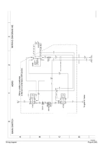
The manual is built as a series of engineering-grade wiring diagrams, each one keyed to a diagram coordinate, component identifier, connector pin and wire number. Rather than a generic schematic, the Volvo FE electrical wiring manual presents the network exactly as it is laid out on the truck: power distribution, UADR, ABS/ECS, EBS, hybrid high-voltage areas, engine management, cab, chassis and trailer interfaces, all mapped to the same identification system.
File Details
- Manual type: Component wiring diagrams / electrical service manual
- Brand: Volvo
- Model: FE
- Order number: 89046088
- Edition / Release: Release 05
- Publication date: May 2012
- Service manual group: 37
- Language: English
- Page count: 229 pages
- File format: PDF
Chapters Covered
- Component wiring diagram index
- Component wiring diagrams
- Illustrations index
- Illustrations
- Fuses
- Relays
- Wiring harness illustration index
- Ground connections
- List of connectors
- List of wiring numbers
- List of components
- Abbreviations
Component Wiring Diagrams
The heart of the manual. Each sheet presents a subsystem with its own coordinate grid, showing the component symbol, the splice or junction, the fuse feeding it, and the reference arrow that tells you which diagram and coordinate the circuit continues on. You get the full power distribution network, main switch and ignition feeds (kl.30, kl.15/DR), the UADR and battery main switch circuits, and the distribution paths that feed every downstream module. Diagram AB_Hyb covers hybrid power supply distribution including the 600 V DC electrical steering pump circuits and the 24 V/12 V distribution for the hybrid area.
Fuses and Relays
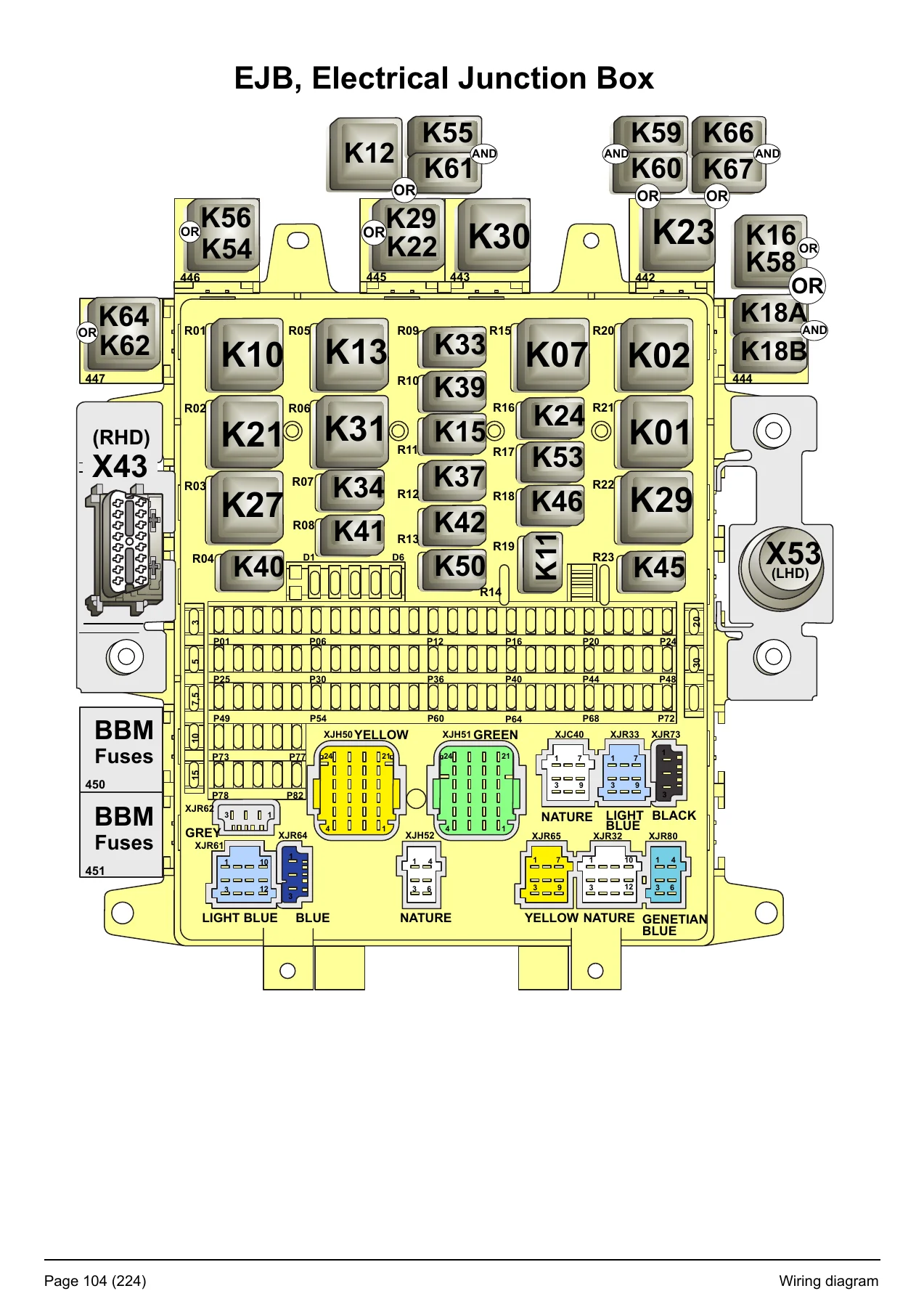
A dedicated fuse list gives the ampere rating, circuit name and the connector/position each fuse serves — including the hybrid junction box (X77) fuse set that covers EPS cooling fan supplies, ESS cooling pump, HPCU power relay, MDS cooling pump, auxiliary converter and 600/24 V DC/DC ignition circuits. The relay section lists each relay by designation (K-number), function and diagram coordinate, so you can go straight from a suspect relay to the circuit it controls. Relay coverage includes power supply kl.15, EMS, intermittent wiper, air suspension, compressor magnetic clutch, alternator controlled, windscreen heater, cab tilt, starter control, motor headlamp washer pump, beacon warning light, high beam, reverse, brake, fog and horn relays.
Wiring Harness Illustrations
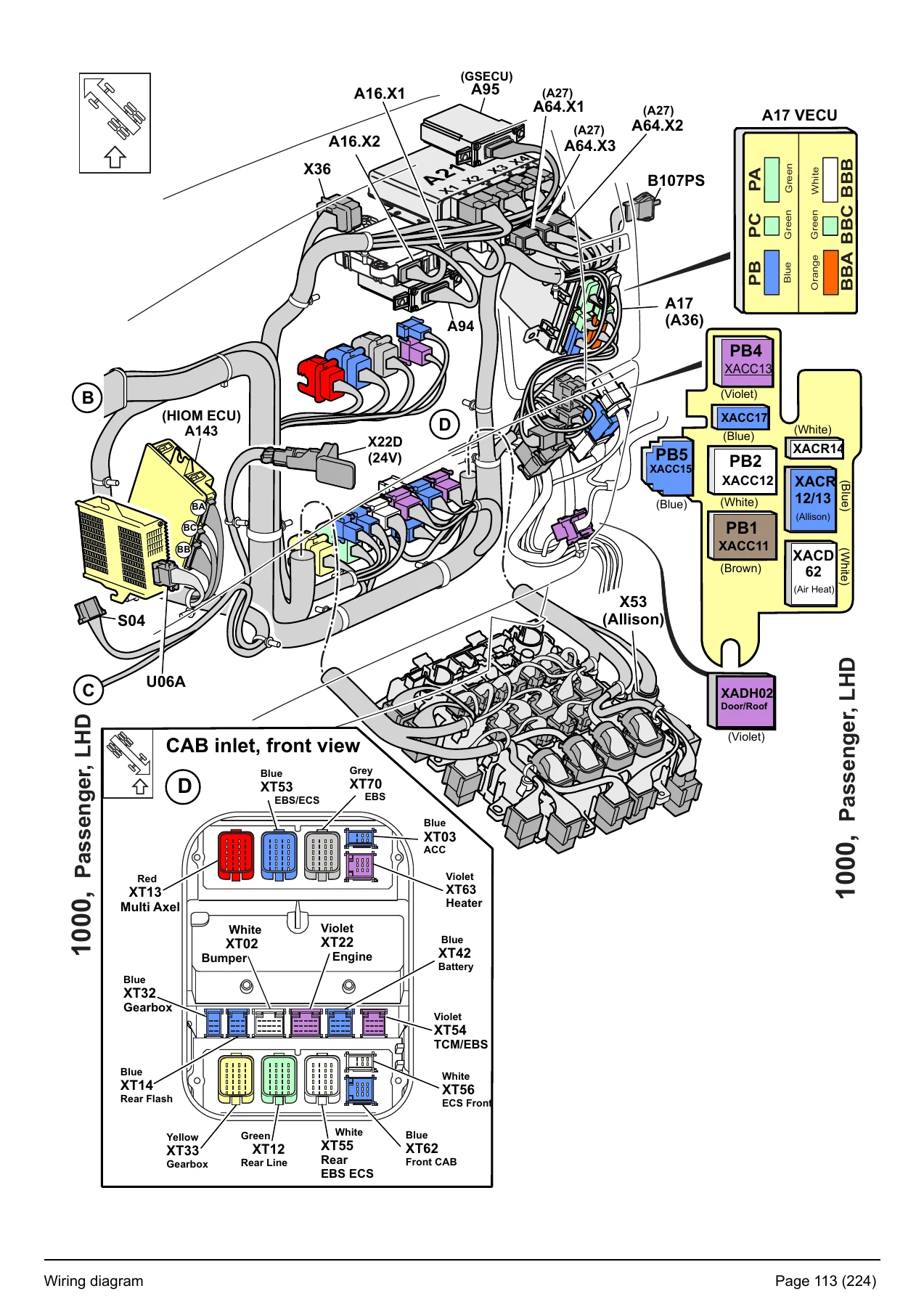
Each harness has its own pictorial illustration showing physical routing and connector locations on the truck — instrument harness (1000), roof (1006), floor (1007), engine (1030), frame (1040), roof beacon light (1047), chassis (1057), trailer connections (1063), door (1083), main switch (1435), bumpers (1447), cab battery box (1460), gearbox (1494), cab gearbox (1499) and upper front (1501). Separate LHD and RHD illustrations show drive side, steering wheel, passenger side and cab inlet layouts, so you can see exactly where a connector physically sits before you start pulling trim.
Ground Connections
A complete ground point list, indexed by ground number and diagram coordinate, covering engine ground, battery box grounds, cab grounds, frame grounds (right side and left side), bumper grounds for LHD and RHD, and hybrid-area grounds (JB5_Hyb). Each entry tells you the diagram and grid position so you can trace an earth fault without guessing.
List of Connectors
Every connector is broken out pin by pin — pin number, circuit function, wiring number and the diagram coordinate where it appears. This covers the main ECU connector (X1/X2), the EBS front and rear modulators, the EBS ECU connectors (X3/X4), the electrical junction box (EJB) connectors, cab inlet connectors, diagnostic plug, body builder connectors (PB4, PB5), trailer sockets (ABS/EBS, 15-pole), the tachograph and speed sensor connector, the radio/USB/AUX connectors, and the hybrid junction box connectors. Pin-level detail is what makes a Volvo FE connector pinout manual genuinely usable in the bay rather than just a picture book.
List of Wiring Numbers and Components
The wiring number index lets you look up any wire and find every diagram it appears on. Wire number families follow a documented logic — the first digit identifies the circuit family: 1 ground and negative supply, 2 positive supply, 3 signal, 4 comfort accessories, 5 security accessories, 6 lighting, 7 instrumentation, 8 body builder, 9 free, 0 electronic/data link. The component list then identifies each device by its designation code (A, B, E, F, G, H, K, M, R, S, U, V, W, X, Y) with its description and diagram coordinates.
System Coverage in Detail
Systems documented across the diagrams include: Fleet Management System (FMS) gateway with serial data, speed pulse and ignition power; EBS front and rear modulators with wheel speed sensors and brake lining wear indicators; ECS electronic controlled air suspension with chassis level sensors and pressure sensors; EBS trailer control including TCM inlet/outlet/backup valve control and trailer CAN; hybrid high-voltage systems with HPCU, ESS cooling, MDS cooling, resolvers, HVIL in/out loops and 600 V DC/DC conversion; engine management for Euro 3/4 and Euro 5 with unit injector solenoids, rail pressure, boost pressure and coolant temperature sensors; NOxCare dosing, tank heating, level and temperature sensors; ADR circuits; body builder connectors with PTO request/feedback, PWM outputs, CAN and engine speed control; theft alarm; radio and audio including USB and AUX; interior and exterior lighting; rear lamps and fog lights; horn; air heater; heated adjustable mirrors; sun roof and window lift; and cab tilt / park brake / engine running time counter circuits.
Also Included
The foreword explains the observation, caution, warning and danger levels used throughout, and confirms the manual is based on designs and methods studied up to May 2012. An abbreviations section decodes every shortened term used in the diagrams — ABS, ACU, ADR, APM, ASR, BBM, CLU, EBS, ECS, ECU, EJB, EMS, EPG, ESS, FMS, GSECU, HIOM, HPCU, LCM, LHD, OBD, PEC, PTO, PWM, RASEC, RHD, RPM, SUSPL-EC, TECU, VECU and more. A note at the front warns that the maximum number of variants is drawn, so not every wire and component shown will be fitted to every market or vehicle model — worth reading before you assume a circuit is missing from your truck.
Why This Manual Matters in the Workshop
Electrical faults on a modern truck are rarely solved by swapping parts. They are solved by knowing which pin carries the signal, which fuse protects the circuit, where the splice sits, and which ground the module relies on. That is exactly what a Volvo FE wiring diagram PDF gives you. The coordinate system, the wire number logic and the pin-level connector tables combine into a traceable path from symptom to source — whether that is a dead circuit on the body builder connector, a wheel speed fault on the EBS modulator, a NOxCare sensor reading out of range, or a hybrid interlock loop that will not close.
For anyone maintaining, repairing or upfitting a Volvo FE, the wiring diagram set is not a nice-to-have. It is the difference between a two-hour diagnosis and a two-day guessing game. Fuse ratings matter — fitting the wrong ampere fuse to the hybrid junction box or the EBS supply can turn a minor fault into a module failure. Connector pinout matters — back-probing the wrong pin on the EBS ECU or the FMS gateway risks damaging a control unit. Ground point location matters — a corroded frame earth will mimic a dozen unrelated faults until you find it. This manual removes that guesswork.
IMAGES PREVIEW
Instant Delivery, Any Device
The complete Volvo FE electrical service manual is delivered as an instant PDF download immediately after payment — no shipping, no waiting for a disc, no dealer visit. Open it on a laptop in the cab, a tablet on the bench, or a phone at the side of the truck. Print the sheets you need for the job and take them to the vehicle without worrying about damaging the original. Every page, every diagram, every pin table, in one file, ready the moment you need it.
Reviews
There are no reviews yet.