
Renault T High Truck Wiring Diagram Manual 2023 – 337014/25 Complete Electrical Schematics PDF
Original price was: $59.95.$39.95Current price is: $39.95.
Complete 830-page Renault T High wiring diagram manual (337014/25, 2023) covering CAN BUS and LIN BUS architecture, Euro III, Euro V and Euro VI emissions, ACM 1.0, ACM 2.0 and ECM 4.0 control modules, shared functions, harness routings, connector pinouts, fuses and relays. Instant PDF download.
Description
Renault T High Wiring Diagram Manual – Document 337014/25 (2023)
This is the complete Renault T High wiring diagram manual, issued under document number 337014/25 in 2023. Across 830 pages it documents the full electrical architecture of the T High truck range, covering CAN BUS and LIN BUS networks across Euro III, Euro V and Euro VI emissions configurations, including ACM 1.0, ACM 2.0 and ECM 4.0 control module variants. Every shared function, harness routing, connector pinout, fuse assignment and relay table is laid out sheet by sheet in the same format used for Renault Trucks workshop documentation.
File Details
- Manual type: Wiring diagram / electrical schematics manual
- Brand: Renault Trucks
- Model: T High
- Document number: 337014/25
- Year: 2023
- Language: English
- Page count: 830
- File format: PDF
Chapters Covered
- Communication Bus Architecture
- Shared Functions
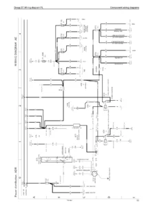
- Wiring Diagrams
- Equipment Locations
- Layout of Controls
- Electrical Distribution
- Available Power Supplies
- Wiring Harnesses
- Cab Inter-Connectors
- Chassis Inter-Connectors
Communication Bus Architecture
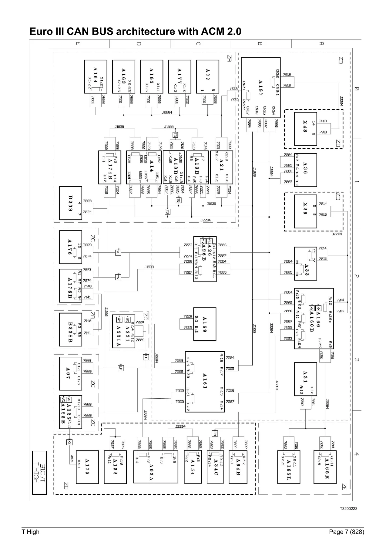
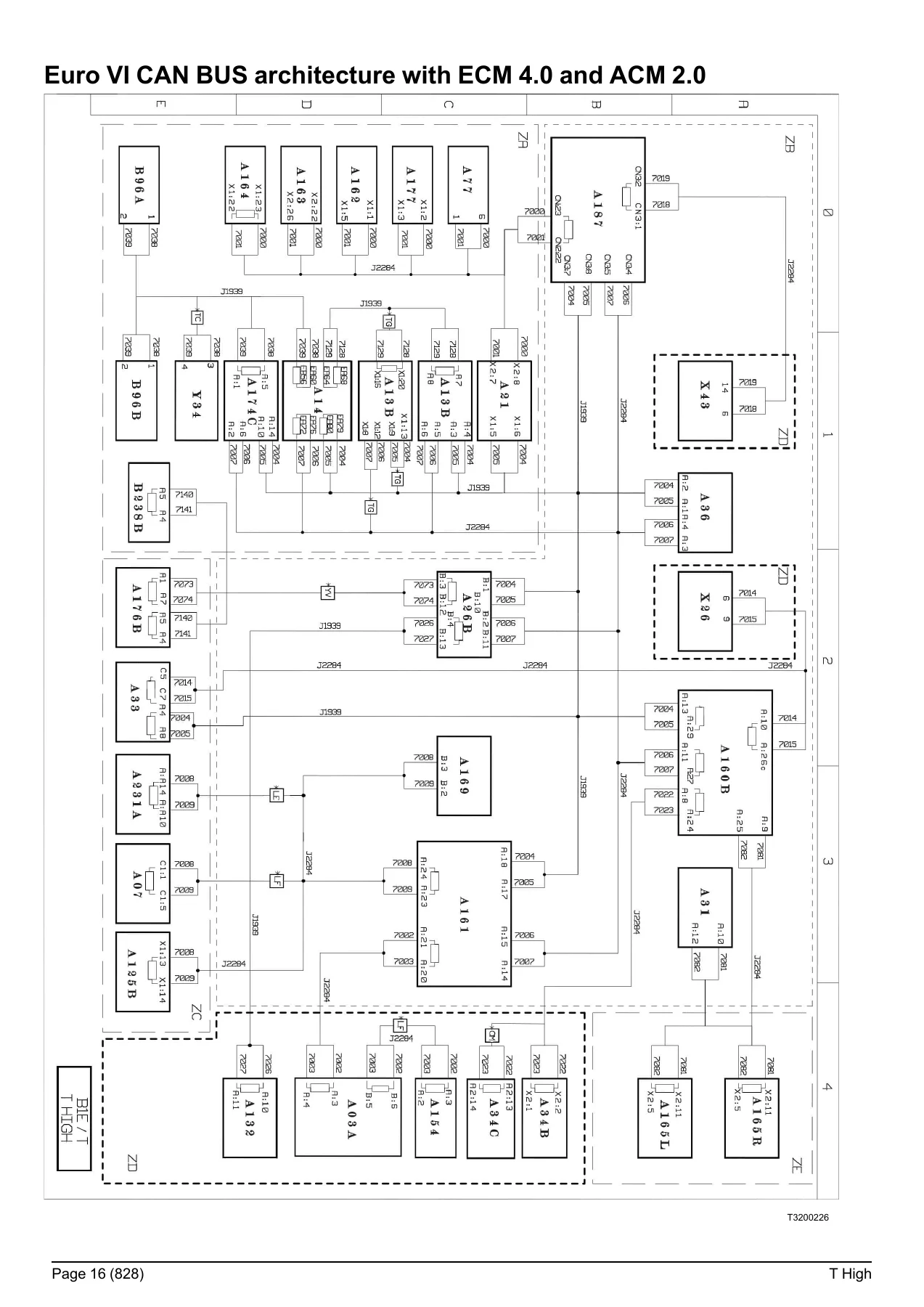
The opening chapters map the complete network topology of the T High. Separate diagrams are provided for Euro V CAN BUS with ACM 1.0, Euro III CAN BUS with ACM 2.0, Euro III CAN BUS with ECM 4.0 and ACM 2.0, Euro V and Euro VI CAN BUS with ACM 2.0, Euro VI CAN BUS with ECM 4.0 and ACM 2.0, and the LIN BUS architecture. Each sheet carries an equipment key identifying control units such as the EECU, EBS, DACU, ACM, APM, VMCU, CIOM, HMIOM, FCIOM, CCIOM, RCIOM, DDM/PDM, tachograph, TGW3, telematics units and tyre pressure monitoring. Bus transfer zones for J1939, J2284 main, J2284 chassis, J2284 human/machine interface and J2284 cab information are each given their own sheet.
Shared Functions
This is the top-level electrical reference for the truck. It opens with distribution and management of electrical power in both non-ADR and ADR configurations, then works through display, door locking/unlocking, alarm, interior lighting and exterior lighting (each split by production date), immobiliser, Euro V emissions, Euro VI emissions, Euro VI Step-E anti-pollution, air production management, air conditioning (standard and with CCM4), air suspension, windscreen wiper and washer, electric rear-view mirrors, controlled axle, safety and driving assistance, braking management (including 4×2/6×2 and trailer-specific sheets), engine management, transmission, automated manual transmission (including TRAG-G), retarder, tachograph, and windows and sunroof. Each function is drawn as a shared-function schematic with its equipotentials, communication buses and associated equipment clearly identified.
Wiring Diagrams
Over 250 pages of individual circuit diagrams cover the full equipment list. Separate diagram sheets are indexed for the cab electrical distribution box, main information display (short and long dashboard variants), tachograph, engine management for 13-litre engines across Euro V, Euro VI Phase 1 (OBDEP-A), Phase 2 (OBDEP-C), Phase 3 (OBDEP-D), Phase 4 (OBDEP-E) and Turbo Compound Step-E, fuel heating, engine preheating, urea solution supply for Euro V ACM 1.0, Euro V ACM 2.0, Euro VI and Euro VI Step-E, automated manual transmission, TRAG-G, retarder, EBS equipment with front, rear, trailer and TAG/PUSHER modules, tyre pressure monitoring, air suspension 4×2 and 6×2, lift axle, controlled axle, air production, immobiliser, door management, alarm, video surveillance, Alcotest, headlights, rear lights, side parking lights, roof-mounted parking lights, horn, windscreen washing and wiping, driving radar, cab compartment lighting, independent heaters, parking coolers, air conditioning, heated seats, windscreen de-icing, sunroof and sun visor, radio, entertainment module, TV/DVD, 12V sockets, accessory sockets, control/command, cab tilting, trailer connections and body builder pre-equipment.
Equipment Locations
The equipment location section shows where every major component physically sits on the vehicle. It includes the cab distribution box layout, main information display layouts for both dashboard lengths, tachograph, 13-litre engine electronic management layouts for Euro V, Euro VI Phase 1, Phase 2/3/4 and Turbo Compound Step-E (single and dual battery variants), fuel management, urea supply management for right-hand under-cab tanks, right-hand side tanks and left-hand side tanks, telematics, Era-Glonass, energy production with battery box on left or rear (single and dual battery, ADR and non-ADR), air production on rigid and tractor, gearbox management, retarder variants, brake pad wear sensors, EBS for rigid, tractor and 4×2/6×2 PUSHER/TAG, air suspension layouts, controlled axle 6×2 PUSHER and TAG, fifth wheel, tyre pressure monitoring, differential lock on rigid and tractor, data link connectors, power take-off on rigid and tractor, door management, immobiliser, alarm, bodywork pre-equipment, independent heating, air conditioning, night-time air conditioning (SP950 and SPX1200), radio, sunroof, accessory sockets, heated seats, windscreen de-icing, driving assist, cab tilting, video surveillance and interior/exterior lighting management, plus cab, chassis and 13-litre engine earths.
Layout of Controls
Two dashboard switch layouts are provided, one for vehicles manufactured before 2021/05/24 and one for vehicles manufactured after 2021/05/23, plus an overhead ledge layout. These identify the position of switches such as the alarm panic button, fuel heating control, body builder pre-equipment controls, repositionable control groups 1, 2, 3 and 5, external lighting control unit, cruise control assembly, cab lighting control, passive start/stop switch, emergency stop control, emergency call control, roof identification light control and passenger side front curtain control.
Electrical Distribution
The electrical distribution section contains the fuse tables for the cab distribution box (F01 through F91), relay tables (K01 through K28), external fuse tables (FM1 through FM15 and F92 through F126), external relay tables (K30, K69, K94A, K94B, K95), fuse and relay tables for dual-battery vehicles, and the face A and face B connector pinouts for the electrical distribution box. Every fuse and relay is listed with its amperage, the equipment it protects and the relevant diagram sheet.
Available Power Supplies
This section lists the take-off points available inside the cab and on the chassis, giving for each one the connector marking, the polarity number and the rating in amps. Locations covered include the cab overhead ledge, console, telephone and CB pre-equipment, driving assistance pre-equipment, telematics pre-equipment, bodybuilder pre-equipment connectors BBEC1A, BBEC2A and BBEC3A, side parking lights, and the working area spotlamp. It also states the mandatory rule that electrical take-offs must be made only on the power supplies provided by Renault Trucks, using type-approved connectors and harnesses.
Wiring Harnesses
The harness routing section documents the physical path of every major harness on the vehicle, including the electrical distribution harness, main CAN bus J1939 harness (before and after 2017/12/04), information display harness, tachograph harness, 13-litre engine harness for Euro V, Euro VI Phase 1, Phase 2 and Phase 3/4 in single and dual battery variants, 13-litre Turbo Compound Step-E harness, urea supply harness for Euro V, Euro VI Phase 1/2 and Phase 3/4, dual battery harnesses with batteries at the rear or left (ADR and non-ADR), telematics harness, Era-Glonass harness, automated manual transmission harness for Euro V, Euro VI and TRAG-G, EBS harness, suspension harness, door harness, alarm harness, air conditioning harness (standard and CCM4), audio system harness, accessories harness, heated windscreen harness, driving assist harness, cab tilt harness, cab interior and exterior lighting harnesses, windscreen wiper harness, and controls harness.
Cab and Chassis Inter-Connectors
The final two sections give the pinout of every intermediate connector in the cab and on the chassis. Cab inter-connectors cover BBEC1A, BBEC2A, BBEC3A, XC110, XC136 to XC140, XC146, XC148, XC150, XC151, XC156, XC158, XC160 to XC175, XC176 to XC181, XC183, XC184, XC186, XC187, XC188, XC189, XC190, XC191, XC193, XC194, XC195, XC197 to XC199, XC214 to XC216, XC404, XC405, XC414, XC415, XC437, XC439, XC440, XC441, XC446, XC456 and XC468. Chassis inter-connectors cover XC301, XC302, XC303, XC312, XC313, XC314, XC315, XC316, XC317, XC318A/B/C, XC319, XC321 to XC323, XC325, XC327, XC328, XC330 to XC332, XC342, XC351, XC355, XC357, XC377, XC378 and XT65, with each pin identified by function, polarity number and diagram sheet.
Why This Renault T High Wiring Diagram Manual Matters
Electrical faults on a modern T High are rarely solved by guessing. The truck runs multiple CAN BUS networks at different speeds, a LIN BUS for body functions, and a long list of control units that all need to talk to each other. Without the correct wiring diagram you are left chasing wires with a multimeter and hoping. This manual removes that guesswork. It tells you which pin on which connector carries which signal, which fuse protects which circuit, where each harness runs, and how each shared function is wired across the different emissions and control-module configurations. That means faster diagnosis, fewer parts swapped on suspicion, and repairs done the way Renault Trucks intended.
What You Can Do With It
- Trace a no-start, no-crank or intermittent electrical fault back to the correct fuse, relay, connector pin or earth point
- Confirm the pinout of any cab or chassis inter-connector before back-probing
- Identify the correct CAN BUS architecture for the vehicle’s emissions level and ACM/ECM variant
- Follow the physical routing of a harness when replacing or repairing damaged sections
- Check the correct amperage of every fuse in the cab distribution box and the external fuse box
- Find the location of every control unit, sensor, solenoid valve and lamp on the vehicle
- Work on Euro III, Euro V and Euro VI T High trucks with one reference
- Understand the ADR and non-ADR electrical supply arrangements, including dual-battery configurations
- Use the equipment keys to decode the abbreviations used on every diagram sheet
- Support body builder work using the pre-equipment connector pinouts and available power supply list
IMAGES PREVIEW
Instant PDF Delivery
The Renault T High wiring diagram manual is delivered as an instant PDF download after checkout. There is no shipping, no waiting and no physical book to lose. The file opens on any device with a PDF reader, and every page can be printed at full size for use in the workshop. Whether you are on a laptop in the cab, a tablet on the pit, or a desktop in the office, the complete 830-page electrical reference is available the moment payment clears. Keep it on file and you have the wiring answer for every T High you work on.
Reviews
There are no reviews yet.