
Renault Trucks C Wiring Diagrams Manual 337016/06 – 2017 Electrical Schematic PDF
Original price was: $71.95.$44.95Current price is: $44.95.
Complete 704-page Renault Trucks C electrical wiring diagrams manual, document 337016/06, covering Euro III, Euro V and Euro VI vehicles – shared functions, full schematics, ECU pin-outs, fuse and relay tables, harness routings and trailer connections in one PDF.
Description
This is the complete Renault Trucks C wiring diagrams manual, document 337016/06, issued in 2017. It documents the full electrical architecture of the Renault Trucks C range across Euro III, Euro V and Euro VI emissions levels, from the top-level communication bus layout down to individual connector pin numbers, wire polarities and harness routings. Every shared function, control unit and trailer interface used on the vehicle is covered in this 704-page schematic set.
File Details
- Manual type: Wiring diagrams / electrical schematic manual
- Brand: Renault Trucks
- Model range: C
- Document number: 337016/06
- Publication date: 2017
- Page count: 704 pages
- File format: PDF
- Language: English, with a multilingual information notice in French, Italian, Spanish, Hungarian, Finnish, Czech, Danish, German, Dutch, Polish, Portuguese, Russian and Turkish
Chapters Covered
- Communication bus architecture
- Shared functions
- Wiring diagrams
- Equipment locations
- Layout of controls
- Electrical distribution
- Trailer connections
- Available power supplies
- Wiring harnesses
- Cab inter-connectors
- Chassis inter-connectors
Communication Bus Architecture
The manual opens with the vehicle network layout. Separate diagrams are given for the Euro III and Euro V CAN bus architecture and for the Euro VI version, each listing every device on the bus with its code, function description and physical location on the vehicle, whether dashboard, console, chassis zone, door or roof. Devices listed include the main information display, radio set, automated manual transmission control unit, engine electronic control unit (EECU), electronic braking system control unit (EBS), driving assist management control unit (DACU), tachograph, air conditioning management control unit, body builder pre-equipment management control unit (BBM), tyre pressure monitoring control unit, cab information management control unit (CIOM), man/machine interface management control unit (HMIOM), front, central and rear chassis area information management control units (FCIOM, CCIOM, RCIOM), left and right door information management control units (DDM/PDM), exhaust gas after-treatment control module (ACM), additional telematics management control unit (TESP), air production management control unit (APM), main vehicle management control unit (VMCU), nitrogen oxide concentration sensors and the vehicle diagnostic socket (OBD).
Shared Functions
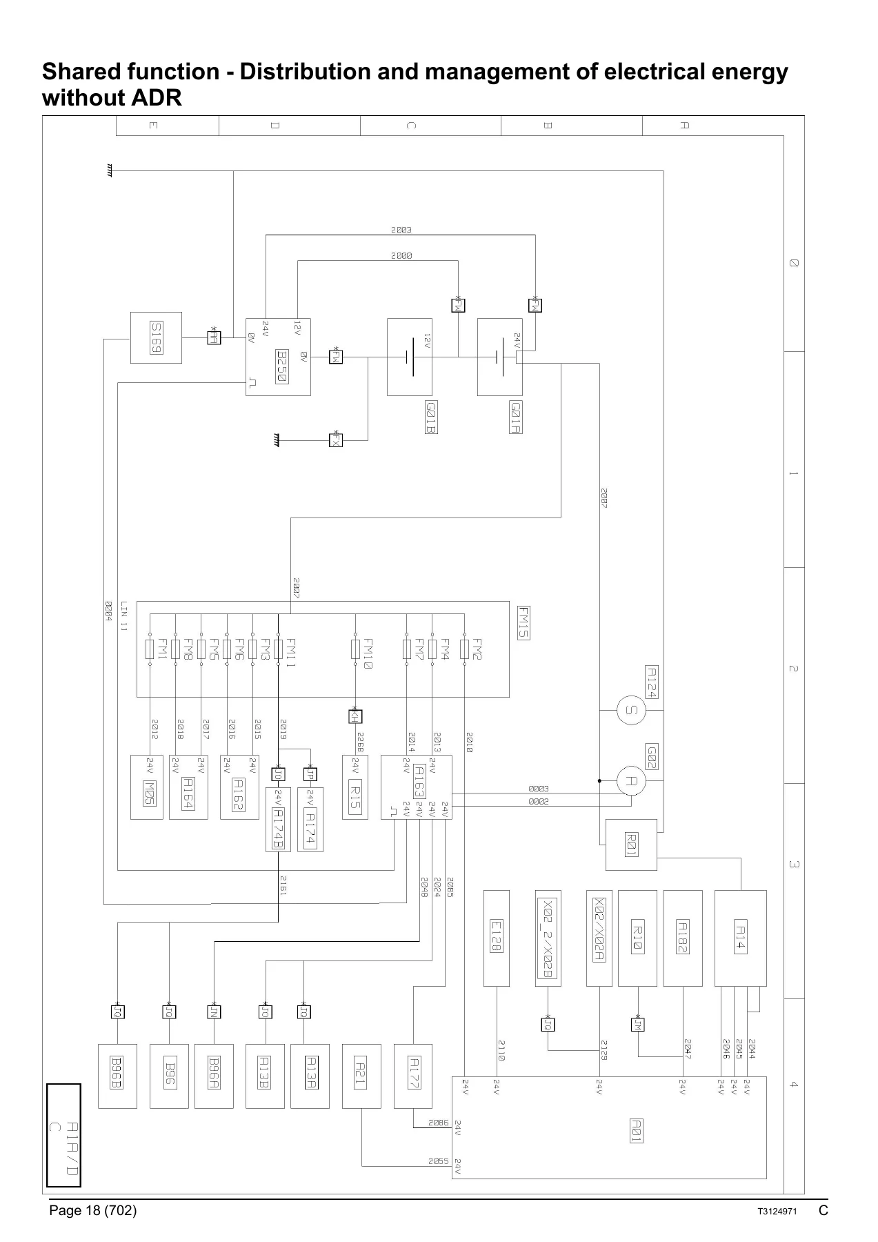
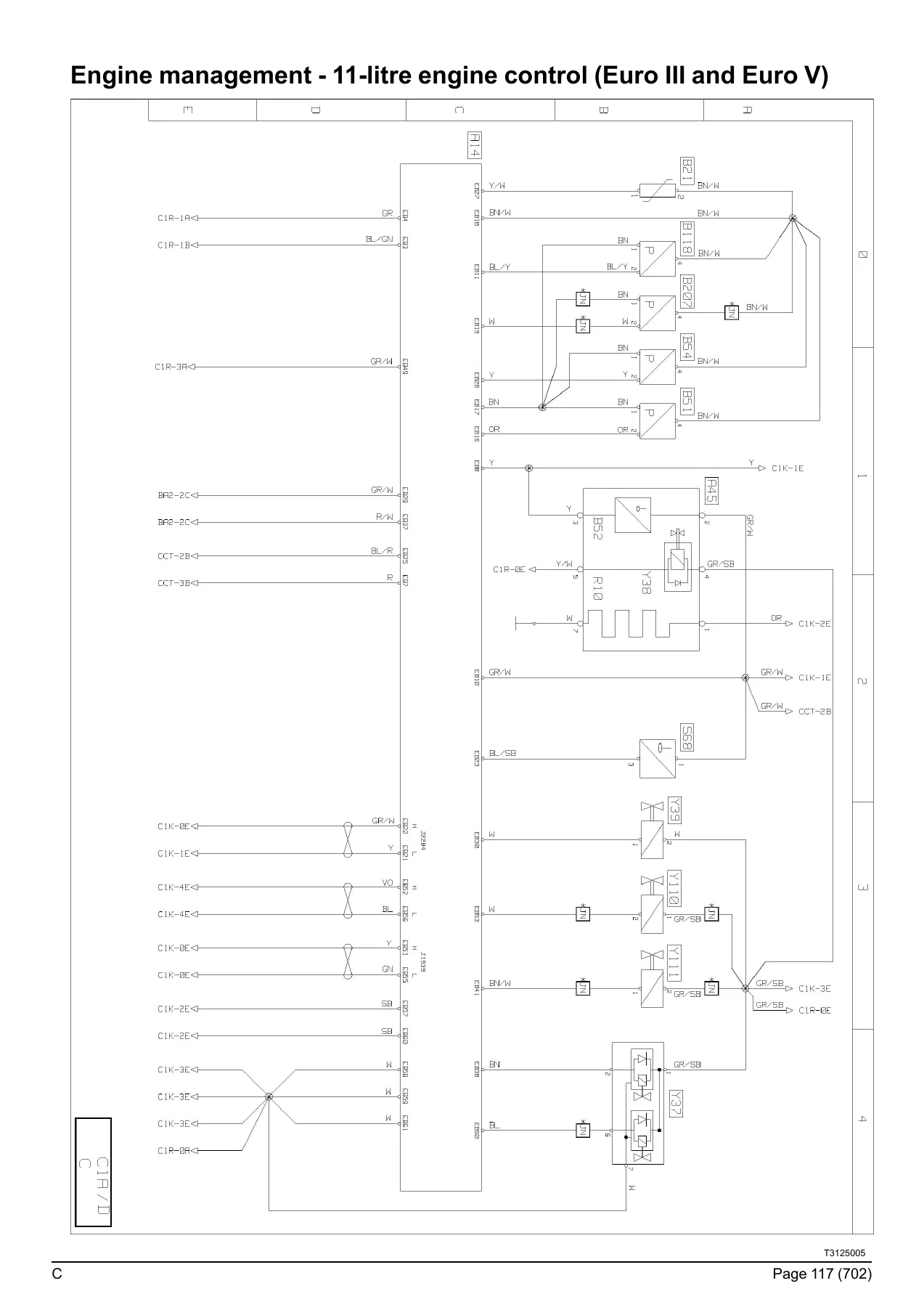
The shared functions section sits at the top level of the schematic set. Each shared function is presented on its own diagram sheet with a reference code and a page number, showing the main equipotentials of the system, the communication buses involved and the equipment that affects that function. The functions covered are distribution and management of electrical power with and without ADR, display, locking and unlocking of doors, alarm, interior lighting, external lighting, immobiliser, Euro V anti-pollution, Euro VI emissions, air production management, air conditioning, air suspension, windscreen wiper and windscreen washer, electric rear-view mirrors, safety and driving assistance, braking management, trailer-specific braking management, Euro III and Euro V engine management, transmission, automated manual transmission management, retarder, tachograph, windows and sunroof, Euro VI engine management, front braking management and rear braking management.
Wiring Diagrams
The main wiring diagram block takes each of those shared functions and breaks it down into conventional electrical schematics with wire numbers, polarity references and the folio page each wire lands on. Coverage runs through energy production for standard production and ADR equipment, electrical distribution on the chassis, vehicle starting, 11-litre and 13-litre engine management for Euro III, Euro V and Euro VI (including Phase 1 OBDEP-A and Phase 2 OBDEP-C variants of the 13-litre Euro VI engine), urea supply for both Euro V and Euro VI with left-hand or right-hand tank, fuel heating, engine preheating, automated manual transmission and manual gearbox management, OptiTrack hydraulic system, hydraulic retarder, EBS equipment for every chassis layout, front and rear EBS modules, brake pad wear sensors, tyre pressure monitoring, air suspension for 4×2, 6×2, 6×4, 8×4 and TAG layouts, lift axle and controlled axle management, power-assisted steering, air production management, immobiliser, left and right door management, alarm, video surveillance, alcotest, main beam and on-site headlamps, rear lights, side and roof marker lights, horn, windscreen washing and wiping, driving radar, cab compartment lighting, independent heating, night-time air conditioning (SP950 and RT880), air conditioning, heated seats, sunroof and sun visor, radio, TV/DVD, 12 V sockets and accessories, accessory sockets, control and command panels, cab tilting and hour meter, trailer sockets, body builder system management and the J1939, J2284 main, chassis information, human/machine interface and cab information CAN bus transfer zones.
Equipment Locations and Layout of Controls
A dedicated locations part shows where each component physically sits on the vehicle. Separate location sheets are provided for the distribution box, main information display, tachograph, 11-litre and 13-litre engine electronic management (Euro III, Euro V and Euro VI, including the Euro VI Phase 1 and Phase 2 variants), fuel management, urea supply management for both tank positions, telematics, power-assisted steering, energy production, air production management on rigid and on tractor, gearbox management, retarder on mechanical and automated manual transmissions, brake pad wear sensors, EBS equipment for rigid, tractor, 4×2, 6×2 TAG, 6×2 and 6×4, and 8×4 and 8×6, air suspension for each axle configuration, controlled axle management, tyre pressure monitoring, differential lock on rigid and tractor, OptiTrack hydraulic system, data link connectors, power take-off, door management, immobiliser, alarm, bodywork pre-equipment, independent heating, air conditioning, night-time air conditioning, radio, sunroof, accessory sockets, heated driver seat, windscreen de-icing, driving assist, cab tilt, video surveillance, interior lighting, exterior lighting, horn, window washing and wiping, and the cab, chassis and engine earth points. The layout of controls part follows with the switch positions on the dashboard and on the overhead ledge.
Electrical Distribution
The electrical distribution part contains the fuse and relay tables for the cab distribution box, the fuses fitted outside the distribution box, the dedicated OptiTrack fuse table and the external relay table. Each entry gives the fuse or relay code, its current rating in amps, the folio where it is used and the function description. The distribution box connector tables then list every pin of faces A and B – A01.CT1, A01.CT2, A01.CB1 through A01.CB12 – with pin number, designation, polarity number and diagram page reference.
Trailer Connections and Available Power Supplies
Trailer wiring is documented pin by pin for the 7-pin ABS/EBS socket, the 15-pin trailer socket and the 7-pin type 24 N and 24 S connections, including the dual-type variants, with the polarity number and diagram page for every pin. The available power supplies section then sets out, location by location, which pre-equipped supplies exist inside the cab and on the chassis, the connector marking they use, their fuse reference and their current rating, together with the manufacturer’s guidance on conductor cross-section and circuit protection.
Wiring Harnesses, Cab and Chassis Inter-Connectors
The harness part gives the routing for each loom in turn – electrical distribution, main J1939 CAN bus, information display, tachograph, each engine variant, the urea supply system for Euro V and Euro VI, telematics, gearboxes, EBS, suspension, doors, alarm, air conditioning, audio system, accessories, windscreen de-icing, driving assist, cab tilt, interior and exterior lighting, and windscreen wiper and washer. Every routing entry names the component, its connector, connector colour and pin count. The cab and chassis inter-connector tables then close the loop, listing each XC connector pin by pin with its designation, polarity number and diagram page, so a wire can be traced from one end of the vehicle to the other.
What These Renault Trucks C Schematics Let You Do
With this Renault Trucks C wiring diagrams manual on hand you can trace a fault through the whole vehicle rather than guessing at it. Find the correct fuse rating before you replace one. Follow a circuit from the distribution box through the cab inter-connector, down the chassis harness and out to the trailer socket. Confirm which pins carry the CAN bus, which carry the supply and which are the earths before you probe a connector. Check the polarity number on a sensor, see which shared function a wire belongs to, and identify the control unit that actually owns the signal. Whether you are chasing an intermittent lighting fault, diagnosing a non-starting engine circuit, repairing a door module, adding body builder equipment, or checking the urea supply and after-treatment wiring on a Euro V or Euro VI vehicle, the schematic, the pin-out table and the harness routing are all in the same document.
Why the Correct Diagram Matters
Electrical work on a commercial vehicle is unforgiving. A mis-identified pin, a fuse fitted at the wrong rating or a circuit back-probed in the wrong place can take out a control unit that costs more than the repair you set out to do. Working from the manufacturer’s own numbering – the polarity references, folio cross-references and connector designations used throughout this manual – keeps your diagnosis on the right circuit and your repairs within the intended protection. It is the difference between replacing parts and repairing the fault.
IMAGES PREVIEW
Instant PDF Delivery
The Renault Trucks C wiring diagrams manual 337016/06 is delivered as a PDF immediately after payment. There is no shipping, no waiting and no physical book to lose in the workshop. Open it on a laptop, tablet or phone at the vehicle, print the pages you need for the job at hand, and keep the full set on file for every Renault Trucks C that comes through the door.
Reviews
There are no reviews yet.