
Volvo FM4 Wiring Diagram Manual 89130303 – 2013 Complete Electrical Service Schematics PDF
Original price was: $59.95.$39.95Current price is: $39.95.
Complete 300-page Volvo FM4 wiring diagram manual, order 89130303, September 2013. Full circuit diagrams, fuse and relay charts, FRC connector pinouts, harness layouts and ground connections for chassis CHID A752768-, B672197-, D200019- and E808718- onwards. Instant PDF download.
Description
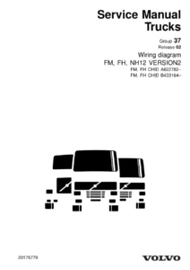
Volvo FM4 Wiring Diagram Manual 89130303 is the complete electrical service documentation for the Volvo FM (4) truck, published by Volvo Truck Corporation in Göteborg in September 2013. This 300-page Volvo FM4 wiring diagram PDF covers the full circuit set for chassis in the CHID ranges A752768-, B672197-, D200019- and E808718- onwards. From engine management and SCR/AdBlue dosing to retarder control, EBS brakes, air suspension, steering and body-builder feeds, every circuit is drawn with cable colours, wire numbers, connector references and component designations exactly as the factory wiring diagram set presents them. If you work on an FM4, this is the electrical service manual you keep open on the diagnostic laptop while you trace a fault.
File Details
- Manual type: Wiring diagram / electrical service documentation
- Brand: Volvo Trucks
- Model: FM (4) — FM4
- Language: English
- Page count: 300
- File format: PDF
- Order number: 89130303
- Edition: Release 01, English 9.2013
- Publication date: September 2013
- Publisher: Volvo Truck Corporation, Göteborg, Sweden
Chapters Covered
- Component wiring diagram index
- Component wiring diagrams
- Illustrations
- Fuses
- Relays
- FRC (A01) connectors
- Wiring harness layout
- Ground connections
- List of connectors
- List of components
- Abbreviations
- Cable colour code
Component Wiring Diagrams
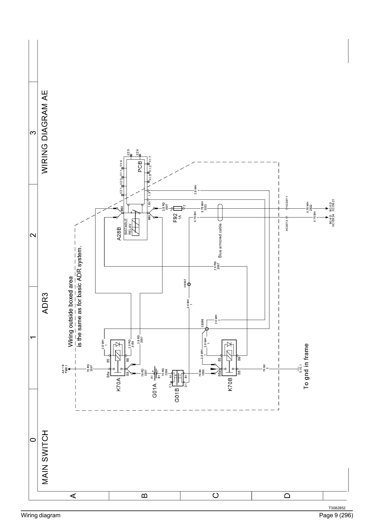
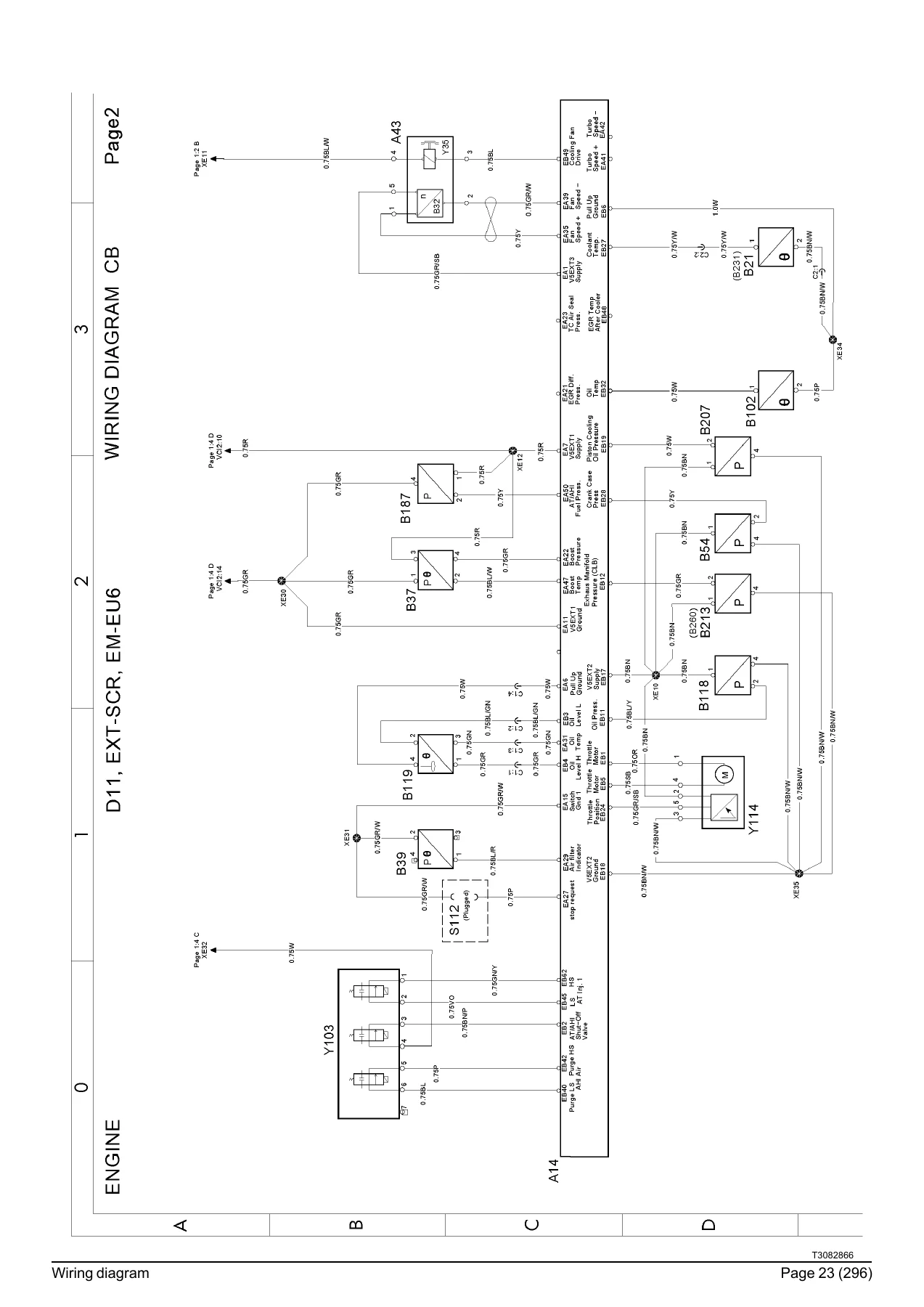
The core of the manual. Every major system on the FM4 is laid out on its own multi-page circuit diagram with a diagram code in the header (AC, AE, AF, BA, CA, CB, CL, DA, EF, EH and so on) — from the D11 and D13 engine interface sections through the SCR/AdBlue aftertreatment, transmission and retarder control, EBS brakes, air suspension, front-axle and rear-axle steering, APM air management, video switch and camera, audio and SID display, to alcolock, SRS airbag and the body-builder circuits. Each diagram carries the full wire path between the two components with the cable colour, wire number, connector designation and pin number at each end, and cross-references in the corner point to the diagram where the other half of the circuit continues.
Fuses and Relays
The FRC (Fuse and Relay Centre) section lists every fuse position in the cab distribution board with its circuit function, wiring number and diagram reference. Fuse ratings and locations for body-builder feeds, EMS, brakes, lighting, mirrors, seats, cab tilt, coffee maker, tachograph, APM and more are all covered. The relay section follows the same pattern, listing the relay code (K01, K02, K07, K10, K16, K21, K27, K65, K69, K70A/B, K90 to K92 and so on), what it switches, and where the coil and contact circuits are drawn.
FRC (A01) Connectors
Pin-by-pin connector tables for the FRC (A01) board, grouped by connector (CB1, CB2, CB3, CB4, CB5, CB6, CB7, CB8, CB9, CB10, CB11, CB12, CT1). For each pin the table lists the circuit function, the wiring number and the diagram where the wire appears, so you can work backwards from a colour-coded pin in the cab to the correct circuit page.
Wiring Harness Layout
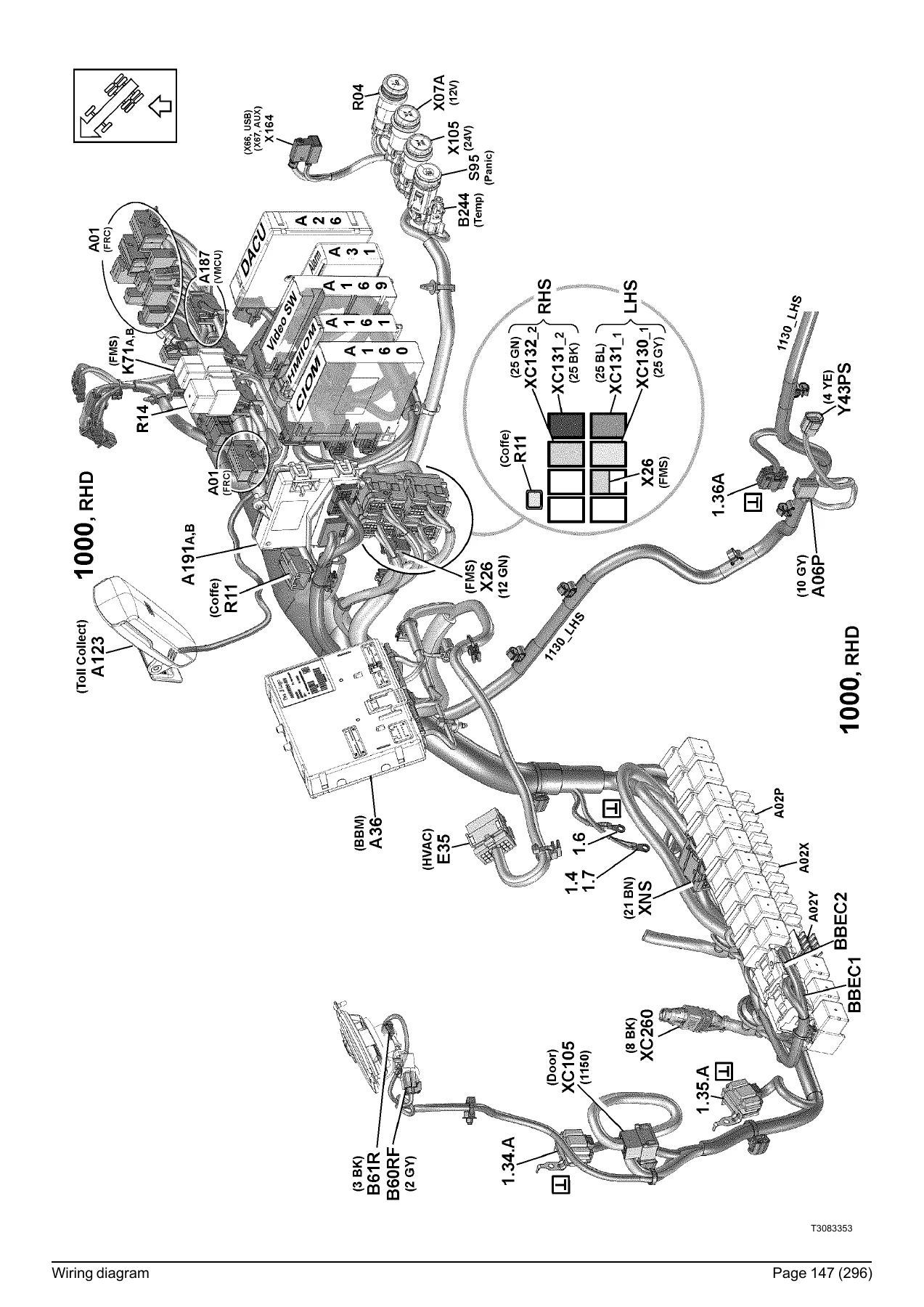
This section provides the physical harness routing for the cab and chassis, with harness codes, splice points, connector markers and mounting references printed onto line art of the FM4 cab and chassis. It is the bridge between the schematic diagrams and what you actually see when you open the cab trim or crawl under the chassis frame.
Ground Connections
Every ground stud is listed with its ground-point number (1.0, 1.1, 1.2, 1.12, 1.30, 1.31, 1.32, 1.33, 1.34, 1.35, 1.36, 1.38, 1.39, 1.40, 5.1, 5.3, 5.5, 5.6, 5.7 and more), its physical location on the truck, and the diagram where it appears. Ground reference numbers on a wiring diagram look abstract until you map them back to a real stud — this section does exactly that.
List of Connectors and List of Components
Two cross-reference indexes. The connector list gives the pin function, wiring number and diagram for every connector shown in the manual, from XC105 and XC106 through XC369 and beyond. The component list identifies each component by designation — A01 FRC, A14 ECM, A26 DACU, A160 CIOM, A161 HMIIOM, A163 CCIOM, A164 RCIOM, A174 ACM, A187 VMCU, A191 CCM, B13A/B13B wheel speed sensors, B49 steering angle sensor and hundreds more — with its function and the diagram where it is used.
Abbreviations and Cable Colour Code
A full abbreviation list covering ADR, EBS, SCR, TECU, VMCU, BBEC, APM, RAS, EAS, LCS and the other acronyms that appear throughout the diagram set, plus the standard Volvo cable colour code (BK, BN, BU, GN, GY, OG, PK, RD, VT, WH, YE and the alternative engine and transmission code BL, GR, OR, P, R, SB, VO, W, Y). Where a wire has two colours, the manual uses the YE/RD format — first colour is the base, second is the tracer stripe.
Systems Documented in the Volvo FM4 Wiring Diagram
Engine management interface for D11 and D13 (EM-EC06, EM-EU5, EM-EU6), SCR and AdBlue aftertreatment control, transmission and retarder (TECU), EBS brakes on front axle, rear axle and trailer, air suspension (ECS), front-axle steering (FAS), rear self-steered axle (RAS), air management (APM), EACC parking cooler, cab climate, audio and video switch and camera system, SID low and high displays, lane position sensor (LPOS), forward collision warning, lane change support, driver alert support, alcolock, SRS airbag and seat-belt pretensioners, tachograph, toll collect, FMS, body builder electrical centre, cab tilt pump, air and water parking heaters, battery management and main switch. Every one of these systems has its own diagram set in this Volvo FM4 wiring diagram manual.
What the Volvo FM4 Wiring Diagram Manual 89130303 Lets You Do
This is not a training book or a summary — it is the full electrical reference set behind a Volvo FM4 truck. That means you can chase a no-start, a lamp that stays on, a relay that clicks but does not pull in, a CAN fault that only shows up in wet weather, or a fuse that keeps blowing, and actually follow the wire from the fuse to the component it feeds using the exact pin and colour the truck was built with. Each diagram shows the wire number and connector position, so you can confirm the circuit at the connector instead of guessing at the loom. For diagnostics on a truck that is throwing fault codes at you, that difference between a generic wiring diagram and the real thing is everything — and with this Volvo FM4 electrical service manual the entire system is documented in one place.
IMAGES PREVIEW
The manual is delivered as an instant PDF download. No shipping, no waiting for a disc. It opens on any laptop, tablet or phone, pages print cleanly if you prefer working from a paper copy in the cab, and the diagram references let you jump straight from the fuse list to the circuit page. Keep it on the workshop PC and the diagnostic laptop, and the FM4 electrical system is fully documented every time you open it.
Reviews
There are no reviews yet.