
DAF CF65 CF75 CF85 Electrical System Service Manual – Earlier Chassis Version PDF
Original price was: $63.95.$39.95Current price is: $39.95.
Comprehensive electrical system service manual for DAF CF65, CF75 and CF85 trucks (Earlier Chassis Version). Covers batteries, alternator, sensors, wiring, connectors, fault finding, circuit diagrams and diagnostics. Instant PDF download.
Description
DAF CF65 CF75 CF85 Electrical System Service Manual — Earlier Chassis Version
This is the complete DAF CF65 CF75 CF85 Electrical System Service Manual for the Earlier Chassis Version, supplied as an instant PDF download. Whether you are a workshop technician maintaining a fleet, an owner-operator diagnosing a persistent fault, or a mechanic tackling a wiring repair for the first time, this DAF CF electrical service manual gives you the test procedures, component descriptions, wiring diagrams and connection data you need to get the job done correctly.
The manual covers the full electrical system of the DAF CF65, CF75 and CF85 series, from the batteries and alternator through to sensors, relays, connectors, wiring harnesses and CAN network. It includes detailed fault-finding tables, circuit diagrams, section diagrams, component location drawings, connector pin patterns and service procedures for repairing and replacing electrical components.
File Details
- Manual type: Electrical System Service Manual
- Brand: DAF
- Model: CF65, CF75, CF85 series
- Version: Earlier Chassis Version
- Language: English
- Format: PDF
- Document number: 1358030 (circuit diagram references)
- Date: 200315 (March 2015)
Chapters Covered
- Components — General, tightening torques
- Batteries — Fault-finding table, service life
- Alternator — Fault-finding table
- Fault Finding — Short circuits, open circuits, earthing problems
- General — Multimeter, scopemeter, signal measurements
- Description of Components — Inductive sensors, vehicle speed sensor, temperature sensors, fluid level sensors, pressure sensors, alternator, proximity sensors, steering column switch
- Diagnostics — Diagnostics in electrical systems
- General — Connectors, contacts, contact kits
- Removal and Installation — Connectors, contacts, fitting contacts to wires, SCAT seal, buffer connection, earth wire, CAN network wiring
- Batteries — Safety instructions, charging, storage, checking
- Connection of Accessories — Spare wires, dashboard lead-through connectors, roof console, radio, telephone, 40 A connector
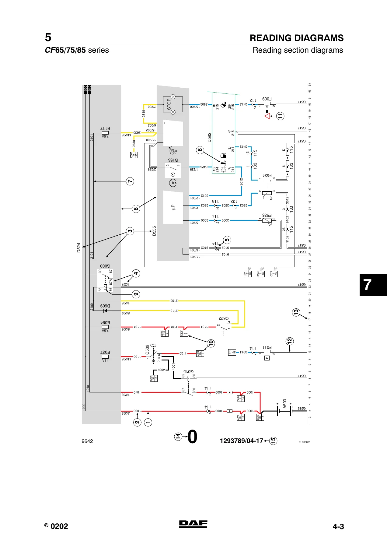
- Reading Diagrams — Marking of electrical wiring, circuit diagrams, section diagrams
- Location of Components — Component locations for circuit diagrams 1358030/15, 1358030/16-24 and 1358030/25
- Location of Connectors — Connector list and drawings
- Electrical System — Circuit diagram 1358030/15, 1358030/16-24 and 1358030/25, including all section diagrams
- Changes in the Electrical System — From chassis number 0E570448 and 0E608863
- Electrical System: Options and Special Applications — Circuit diagram 1454219/03
Components and Technical Data
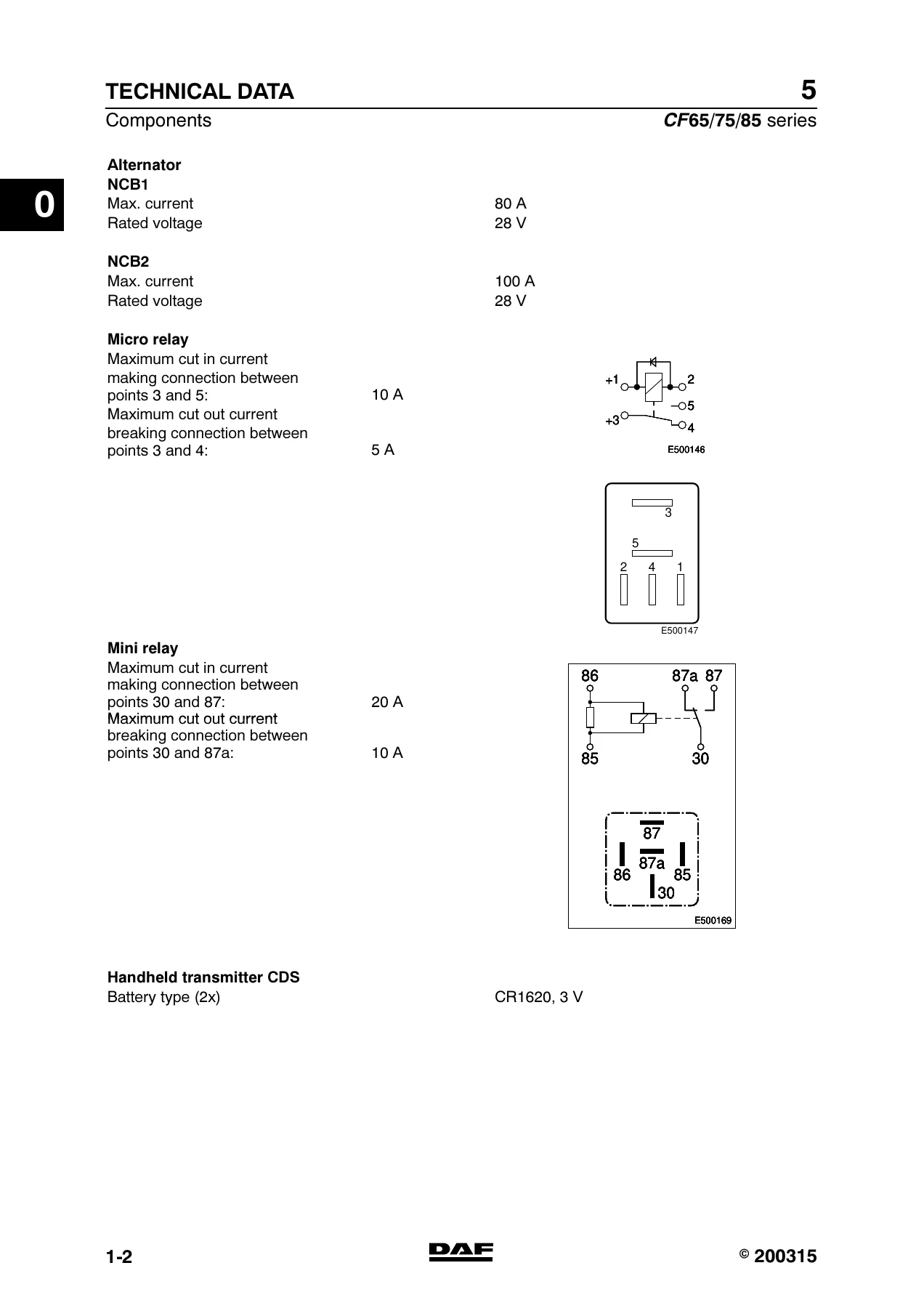
The opening chapters cover the basic electrical components used across the DAF CF65, CF75 and CF85 range. Bulb specifications are listed for headlights, parking lights, rear lights, fog lamps, reversing lights, stop lights, direction indicators, marker lights and interior lighting. Alternator specifications are provided for the 80 A and 100 A units at 28 V. Relay types are detailed, including the micro relay and mini relay with their cut-in and cut-out current ratings. Tightening torques are given for the drive pulley, B+ connection and chassis earth connection.
Batteries and Charging System
The battery section provides a comprehensive fault-finding table covering symptoms such as a new battery heating up during filling, acid leaking from plug holes, low electrolyte level, low relative density, high relative density, starting trouble, burnt battery poles, excessive bubbling under load, fast discharge and short battery life. Each symptom is matched with possible causes and remedies. Battery service life is explained, including the effects of cyclic use, sulphation and the importance of recharging when voltage drops below 12.5 V. The alternator chapter includes fault-finding tables for no power at idle, warning lamp illumination and overvoltage conditions. Charging methods — normal, fast, buffer and trickle charging — are described, along with storage procedures and battery condition checking using relative density and voltage measurements.
Fault Finding and Diagnostics
The fault finding chapter explains the use of a digital multimeter and test lamp for tracing short circuits, open circuits and earthing problems. Short circuit diagnosis using a 70 W test lamp is described step by step. Open circuit testing and earth connection checks using a voltmeter are also covered. A section on signal measurements explains sine-wave and square-wave signals, frequency, voltage, duty cycle and pulse trains. The component description chapter covers inductive sensors (wheel speed, engine speed, camshaft), vehicle speed sensors with duty-cycle output, NTC and PTC temperature sensors, fluid level sensors (coolant and engine oil), pressure sensors for ECAS and boost pressure, the compact alternator with B+, S and L connections, inductive proximity sensors and the redesigned steering column switches with integrated cruise control, engine speed control and intarder functions.
Connectors, Contacts and Wiring Repairs
A substantial section is devoted to the connectors and contacts used throughout the DAF CF series electrical system. It covers connector types, contact sizes and materials, contact kits A and B, and the correct removal and installation procedures using ejector tools. Detailed instructions are given for fitting contacts to electrical wires, including wire stripping lengths, crimping tool selection, crimp height and insulation connection. SCAT seals for harsh environments and electrical buffer connections for wire repairs are described with step-by-step procedures. Earth wire removal and installation is covered with attention to cleaning contact surfaces and applying protective coatings. CAN network wiring repair is also explained, including twisted length tolerances and winding density.
Connection of Accessories
The accessories chapter provides wiring details for spare wires, dashboard lead-through connectors, roof console connections, the 40 A connector, 12 V connection for CB equipment, alarm/immobiliser LED, cooler box, radio and telephone. Pin patterns and wire numbers are given for connectors 580, 581, 597, 618, 656, 654, 655, 657, 658, 588, 576, A068, A070 and others. The dashboard lead-through connector functions are summarised in colour-coded columns (yellow, grey, and others) with row numbers, function descriptions and pin counts. Radio connection details cover ISO-standard connectors, display lighting dimming, station memory for Philips and Grundig radios, and speaker wiring. Telephone connection with 24 V/12 V converter is also documented.
Circuit Diagrams and Section Diagrams
The electrical system chapter contains the full circuit diagrams for the DAF CF65/75/85 Earlier Chassis Version. Circuit diagram 1358030/15 is the base diagram, with 1358030/16-24 covering changes from chassis number 0E570448 and 1358030/25 covering changes from chassis number 0E608863. The section diagrams cover voltage before and after ignition, main switch (VLG/ADR and PETREG versions), alternator/ignition/starter switch/charging circuit, tachograph, immobiliser, pre-glowing, DIP-4 instrument panel, direction indicators and warning lights, VIC, marker and parking lights (FA and FT), UPEC, reversing lights, light switch/fog lights/dipped beam and main beam, Swedish lighting, stop lights/cab tilting gear, differential lock, interior lighting, mirror heating/adjustment, visibility lighting, air conditioning/recirculation/heater fan, seat heating/accessories, horn/cigar lighter/work lamp/air dryer, ABS-ASR-D, DEB, intarder EST42, ECS-DC3, AGS, EMAS, AGC, FAG, PTO, roof spotlights/cooler box/rotating beams, ECAS-3 (4×2), ECAS-2 (6×2), headlamp height adjustment, 24V/12V converter for radio/CB, electric windows/central door locking/roof hatch, mechanical lifting gear, fuel pre-heating, windscreen wiper/washer, Eberspächer Airtronic cab heater, Hydronic 10 cab heater, UPEC/Cummins/AGC application connector, EBS, brake lining wear, alarm system/battery charger, plug sockets, fuel filter/water separator (Racor and Fleet Guard), water separator (Preline), AS Tronic and CDM.
Component and Connector Locations
To help you find components and connectors on the vehicle, the manual includes location lists and pictorial diagrams. The component location lists map basic codes (A000, B010, C539, D900, E286, F533, G015, etc.) to descriptions and physical locations on the chassis, in the cab, in the central box, on the engine and on the gearbox. The connector location lists provide connector coding, number of connection points, colour, description and vehicle location. Pictorial drawings show where to find sensors, electronic units, relays, fuses, valves and connectors across the DAF CF65, CF75 and CF85.
Changes in the Electrical System
Two dedicated sections document changes made to the electrical system in later production. The first covers changes from chassis number 0E570448, including the addition of contact relay G426, changes to fuses E143, E350 and E351, wire changes, mechanical main switch addition, circuit changes in power supply after contact, reversing light relay G350, stop light switch change, search lighting connector and warning lamp additions, PTO activation via VIC, and AS Tronic introduction. The second covers changes from chassis number 0E608863, including earthing point changes, connector changes, clutch protection addition, relay G469 addition, wire 3435 withdrawal, connector changes in interior lighting, seat heating, horn/cigar lighter, ABS, EMAS, FAG, ECAS, mechanical lifting gear, fuel pre-heating fuse value change, windscreen wipe/wash connector change, Airtronic cab heater fuse change, alarm system connector changes, water separator fuse change, AS Tronic connector changes and CDM introduction.
Options and Special Applications
The final chapter contains circuit diagram 1454219/03 for electrical system options and special applications. This includes 12 V sockets, semi-trailer sockets, tail lift switch and warning lamps, battery partition for box/radio/tail lift, ECAS leading rear axle functions, PTO operation valves for 2nd and 3rd PTO, engine brake retarder function, air suspension bleed switch, buzzer for door open/handbrake not in use, warning lamps for semi-trailer connection, semi-trailer air pressure, lifting axle lifted, idling PTO, PTO 3rd, engine speed too high, tail lift open and tail lift on. Additional relays and diodes are documented for battery partition, ECAS leading rear axle lowering and lifting, parking brake, engine brake retarder, intarder+DEB, tail lift open and starting circuit interruption during tail lift use.
Why This DAF CF65 CF75 CF85 Electrical Service Manual Matters
Electrical faults on commercial vehicles can be among the most time-consuming and frustrating to diagnose. A single corroded earth point, a chafed wire or a failed sensor can trigger a cascade of warning lights and symptoms that point in the wrong direction. This DAF CF65 CF75 CF85 Electrical System Service Manual gives you the systematic fault-finding tables, the component descriptions and the circuit diagrams to trace faults logically instead of guessing. The connector pin patterns and location drawings let you find the right connector quickly, and the removal and installation procedures show you how to repair wiring and connectors without causing secondary damage.
For workshops maintaining DAF CF65, CF75 and CF85 trucks, having the correct electrical service information is essential. The circuit diagrams cover the complete vehicle electrical system, including the CAN network, VIC, DIP-4, UPEC, ECS-DC3, ECAS, EBS, ABS-ASR-D, intarder, AGC, AGS, EMAS and all lighting, charging and starting circuits. The section diagrams break the system down into individual circuits, making it easier to follow a specific circuit from power supply through fuses, relays, switches, components and earth. The changes sections ensure that you can identify whether a particular circuit applies to an earlier or later chassis number, so you are not working from outdated information.
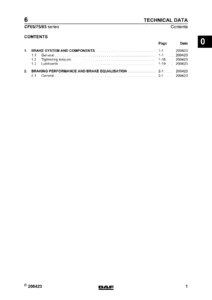
IMAGES PREVIEW
This DAF CF electrical service manual is delivered as an instant PDF download. There is no shipping, no waiting for a physical book, and no risk of a damaged or lost parcel. The PDF can be viewed on any device — laptop, tablet or smartphone — and specific pages can be printed for use in the workshop. Whether you need to check a tightening torque, trace a short circuit, identify a connector pin, understand a sensor output signal or look up a fuse rating, this manual puts the information at your fingertips.
Reviews
There are no reviews yet.