
Renault Trucks T Euro VI Electrical Workshop Manual – Wiring Diagrams, CAN Bus & Connector Pinouts PDF
Original price was: $44.95.$29.95Current price is: $29.95.
Complete 544-page electrical workshop manual for Renault Trucks T Euro VI (2013 onwards). Covers CAN/LIN bus architecture, shared function diagrams, full electrical schematics, connector pinouts, fuse and relay tables, and component locations. Document 337005/02, published 2014.
Description
Renault Trucks T Euro VI Electrical Workshop Manual — 337005/02
This is the complete electrical workshop manual for the Renault Trucks T range built to Euro VI emissions standards, covering vehicles from June 2013 onward. Published under document number 337005/02 in July 2014, this 544-page manual is the technician’s primary reference for every electrical system, circuit, connector, and electronic control unit fitted to these trucks. Whether you are diagnosing a CAN bus communication fault, tracing a wiring harness through the chassis, or replacing a sensor, this manual provides the diagrams, pinout data, and component locations you need.
File Details
- Manual Type: Electrical Workshop Manual
- Brand: Renault Trucks
- Model: T (Euro VI)
- Coverage: 06/2013 onwards
- Document Number: 337005/02
- Revision: 02
- Publication Date: 07/2014
- Language: English
- Page Count: 544
- File Format: PDF
Chapters Covered
- Generalities
- Communication BUS architecture
- Shared functions
- Electrical diagram
- Pinpointing of appliances
- Layout of controls
- Electrical distribution
- Chassis – cab / bulkhead grommet
- Trailer sockets
- Available power supplies
- Wiring harnesses
- Routing of harnesses
- Connectors
Generalities
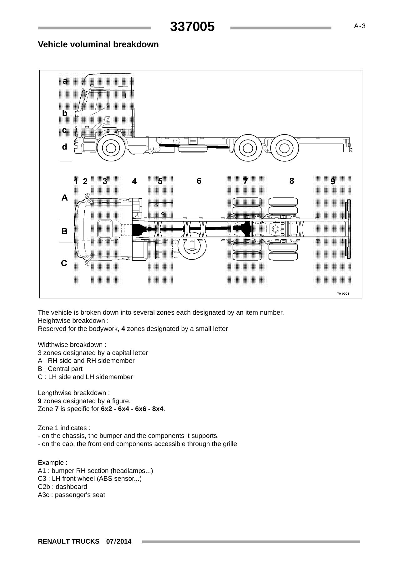
This opening chapter establishes how to use the manual, including the vehicle voluminal breakdown system that divides the truck into lengthwise, widthwise, and heightwise zones. Each zone is designated by a letter and number combination — for example, A1 for the bumper right-hand section, C3 for the left front wheel, and C2b for the dashboard. The chapter also explains how to read the electrical diagrams, including the definition of illustration plates, cross-references, appliance codes, fuses and relays, polarities, graphic conventions, and variants. Device encoding rules are listed, showing the correlation between the first letter of a code and the associated device type — for example, A for ECUs and amplifiers, B for sensors, F for fuses, K for relays, and M for motors. The colour code applicable to connectors and wires is also defined, with alphabetical codes for each colour (BK for black, BU for blue, BN for brown, and so on) and a striped-wire convention where the basic colour is listed first followed by the stripe colour.
Communication BUS Architecture
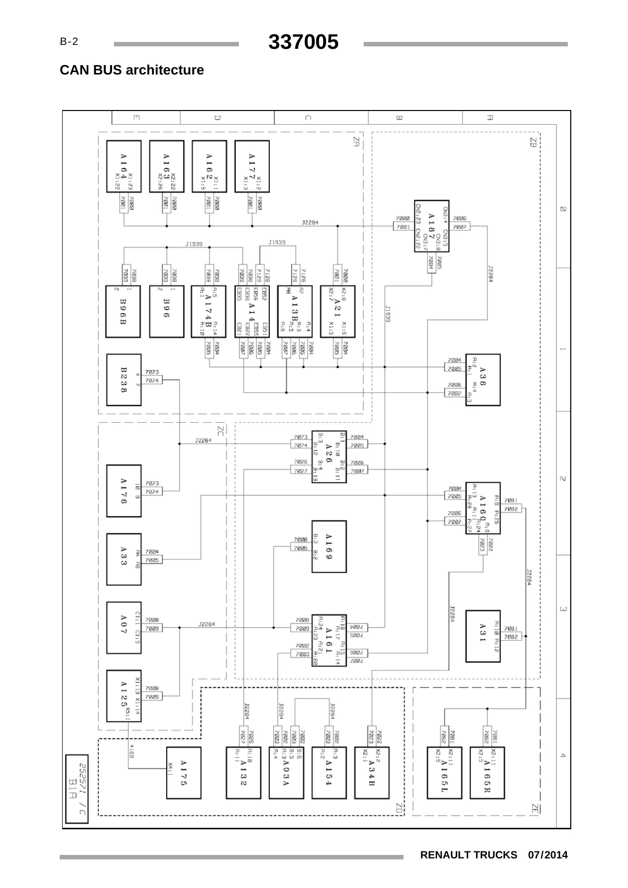
This chapter documents the vehicle’s data communication networks in full. The CAN BUS architecture is presented with a detailed system diagram showing how the various ECUs communicate over the J1939 and J2284 buses. A key to appliances lists every ECU on the network with its function and location — from the engine management ECU (A14) and braking management ECU (A21) to the cab information management ECU (A160) and the rear chassis area information management ECU (A164). The LIN bus architecture is also covered, with its own diagram and appliance key showing the components that communicate over the LIN network, including door modules, climate control panels, rain sensors, and repositionable control units. This chapter is indispensable for diagnosing communication faults and understanding how the vehicle’s electronic systems interact.
Shared Functions
The shared functions chapter is the heart of the manual’s diagnostic content. It presents a series of overview wiring diagrams, each covering one major vehicle system. These are high-level diagrammatics that show the main equipotentials, communication buses, and devices affecting the function. The shared functions covered include: distribution and management of electrical energy (both with and without ADR equipment), display, locking and unlocking of doors, alarm, interior lighting, exterior lighting, immobilizer, Euro VI emissions control, air production management, air conditioning, air suspension, windscreen wiper and washer with horns, electric rear-view mirrors, controlled axle, safety and driving assistance, braking management (including specific 4X2 and 6X2 variations and trailer-specific braking), Euro VI engine management, transmission, robotized gearbox management, retarder, tachograph, and window lift and sun-roof. Each shared function section includes a key to appliances with codes, function names, and locations, enabling quick identification of every component involved.
Electrical Diagram
This is the largest chapter of the manual, containing the detailed electrical diagrams — or “plates” — for the complete vehicle. These plates are numbered and organised by system, with each plate covering a specific circuit or subsystem. The diagrams show every wire, connector, fuse, relay, and component in the circuit, with wire colours, cross-references to other plates, and terminal numbers. The chapter covers energy production (standard and ADR), electrical distribution on the chassis, vehicle starting, vehicle electronic management, the main ECU, main information display, tachograph, fleet management and telematics, engine management for both 11-litre and 13-litre engines (including injection inspection), fuel heating, engine preheating, AdBlue solution addition, gearbox management (both automated manual transmission and mechanical), differential lock, hydraulic retarder, EBS brake management for all options, front and rear EBS modules, brake pad wear sensors, trailer EBS module, TAG or PUSHER module, tyre pressure check, air suspension for 4×2 and 6×2, lift axle management, controlled axle management, air production management, immobiliser, door management (left and right), alarm, video surveillance, breathalyser test, headlights, rear lights, side parking lights, position lights on roof, warning buzzer, washing and wiping of windows, driving radar, cab lighting, independent heaters, air conditioning, heated seats, sun-roof and sun visor, radio, television, 12 V sockets, comfort accessories, control/command units, cab tilt, trailer connections, bodybuilder system management, and CAN bus transfer zones. Earth points for the cab, chassis, and engine are also documented.
Pinpointing of Appliances
This chapter provides a visual guide to the physical location of components on the vehicle. It includes a summary of locations followed by dedicated sections for each major system, showing where ECUs, sensors, actuators, and connectors are mounted. Coverage includes the distribution box, main information display, tachograph, engine electronic management for both 11-litre and 13-litre engines, device layouts on the engine, AdBlue input management, telematics, energy production (battery box on left or rear, ADR equipment), air production management on tractor and rigid, gearbox management, retarder, brake management EBS equipment for various configurations (tractor, rigid, 4×2, 6×2, PUSHER, TAG), suspension management, controlled axle management, fifth wheel management, fuel management, differential lock, diagnostic sockets, power take-off, door management, immobiliser, alarm, bodywork pre-equipment, independent heaters, air conditioning, radio, sun-roof, comfort accessories, heated seats, driving assist, cab tilt, video surveillance, interior and exterior lighting management, warning buzzer, washing and wiping, tyre management, trailer sockets, and earth points for chassis, cab, and engines.
Layout of Controls
This short but practical chapter shows the layout of switches on the dashboard and on the overhead ledge. It identifies the position of each switch and control unit, including the re-positionable control units (groups 1, 2, 3, and 5), the external lighting controls unit, cruise control commands, cab lighting control, alarm panic control, fuel heating resistor control, bodybuilder pre-equipment controls, vehicle emergency stop control, emergency call control, identification lights on roof control, and passenger side front panel control. Note that switch blocks S264, S266, S268, and S261 are interchangeable, and the manual shows the locations as fitted in standard production.
Electrical Distribution
This chapter covers the electrical distribution box inside the cab, which contains most of the fuses and relays for the vehicle electrical network. It includes a comprehensive table of fuses showing the fuse code, function, amperage, and the folio code for the relevant diagram. There is also a table of relays with the same information. A separate table covers fuses outside the electrical distribution box, including the power fuses box (FM15) and the mega fuses for the front, central, and rear chassis information management ECUs. The chapter also documents the connectors on the distribution box, Face A and Face B, with connector item numbers, function names, colours, and number of ways.
Chassis – Cab / Bulkhead Grommet
This brief chapter documents the chassis-cab connection box that enables information to cross the bulkhead between the cab and the chassis. Each connector of the chassis-cab connection is detailed with its item number, function name, colour, and number of ways. Connectors include XC201 for the cab tilt and trailer socket wiring harness, XC203 for the distribution wiring harness for power supplies and information, XC204 for bodybuilder equipment, and XC207 for ADR equipment, among others.
Trailer Sockets
This chapter provides the pinout data for the trailer sockets. The 15-pin trailer socket (X03) is documented with each pin’s function, fuse item number, and amperage. The 7-pin EBS trailer socket (X02) is also covered, showing the function of each pin including trailer 24 V positive supply, power supply after ignition, earth links, ABS safety warning lamp, and CAN BUS J11992-2 connections. This information is essential for diagnosing trailer connection faults and ensuring correct wiring when connecting trailers or semi-trailers.
Available Power Supplies
This chapter lists the available power supplies provided by Renault Trucks for bodybuilders and auxiliary equipment. It includes an important warning that all electrical connections must be made to the available power supplies made available by Renault Trucks, that it is strictly forbidden to make an electrical tapping on any of the different wiring harnesses on the vehicle, and that only officially approved connectors and wiring harnesses must be used. Cable sections should be adapted to the required use, with a recommended value of 7 Amps per mm² for calculating conductor cross-section. The chapter then details supply feeds available inside the cab (locations 1 through 9 and BBEC1A, BBEC2A, BBEC3A) and on the chassis (locations 1, 2, BB1, BB2, BB3), with polarity numbers, fuse item numbers, and amperages for each.
Wiring Harnesses
This chapter provides a summary of routing for the vehicle’s wiring harnesses. Each routing section shows the path of the harness through the vehicle, with a code table listing the function, connectors, colour, and number of tracks for each connector on the harness. Coverage includes the electrical distribution wiring harness, main CAN bus wiring harness J1939, display wiring harness, tachograph wiring harness, 11-litre and 13-litre engine wiring harnesses, AdBlue input system wiring harness, telematics management system wiring harness, mechanical gearbox wiring harness, automated manual transmission wiring harness, EBS equipment wiring harness, suspension wiring harness, door wiring harness, alarm wiring harness, air conditioning wiring harness, audio system wiring harness, accessories wiring harness, driving assist wiring harness, cab tilt wiring harness, cab interior and exterior lighting wiring harnesses, routing on chassis of exterior lighting wiring harness, windscreen wiper and washer wiring harness, and controls wiring harness.
Connectors
The final chapter provides detailed connector views and pinout tables for the dashboard wiring harness and the top ledge wiring harness. Each connector is shown with its item number, function, colour, and number of tracks. The dashboard wiring harness section spans ten parts, covering every connector from the distribution box to the various ECUs, sensors, and accessories. The top ledge wiring harness section spans five parts and covers the connectors for the radio, tachograph, telematics, overhead console, and roof-mounted components. This is the reference for anyone who needs to identify a specific connector, check pin assignments, or trace a wire through a harness.
Why This Manual Matters
The Renault Trucks T Euro VI is a complex, electronically intensive vehicle. Its electrical architecture includes multiple CAN buses (J1939 and J2284), a LIN bus, and dozens of electronic control units managing everything from engine and transmission to braking, suspension, climate control, and bodybuilder equipment. Without accurate wiring diagrams and pinout data, even a simple fault can turn into hours of guesswork. This manual eliminates that guesswork.
Armed with this electrical workshop manual, you can:
- Trace and diagnose faults in any electrical circuit on the vehicle
- Identify the location and function of every ECU, sensor, actuator, relay, and fuse
- Interpret CAN bus and LIN bus communication diagrams
- Read connector pinouts for the dashboard, chassis, engine, and bodybuilder harnesses
- Understand the shared function diagrams that show how systems interact
- Locate earth points and power supplies for diagnostic and repair work
- Correctly wire trailers and bodybuilder equipment using the available power supplies
- Identify the correct fuse or relay for any circuit and its amperage rating
Every procedure, diagram, and table in this manual is specific to the Renault Trucks T Euro VI from June 2013 onward. The document number 337005/02 and revision 02 confirm this is the second issue of the electrical workshop manual, published in July 2014. It is the reference material that professional technicians use when servicing these trucks.
IMAGES PREVIEW
Instant PDF Delivery
This manual is delivered as an instant PDF download. There is no shipping, no waiting for a physical book, and no risk of a damaged or lost package. Once payment is complete, you can download the file immediately and access it on any device — laptop, tablet, or smartphone. The PDF is printable, so you can print the specific diagrams or tables you need for the workshop and keep them at hand while you work.
Whether you are a fleet maintenance technician, an independent workshop, or an owner-operator who prefers to do your own diagnostics, this Renault Trucks T Euro VI Electrical Workshop Manual gives you the same information the professionals rely on. Stop guessing. Start diagnosing with confidence.

Reviews
There are no reviews yet.