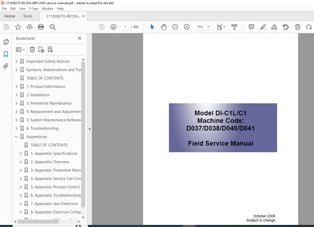
Ricoh MP C2030 / MP C2550 Service Manual PDF (Service & Repair Guide)
Original price was: $85.00.$21.95Current price is: $21.95.
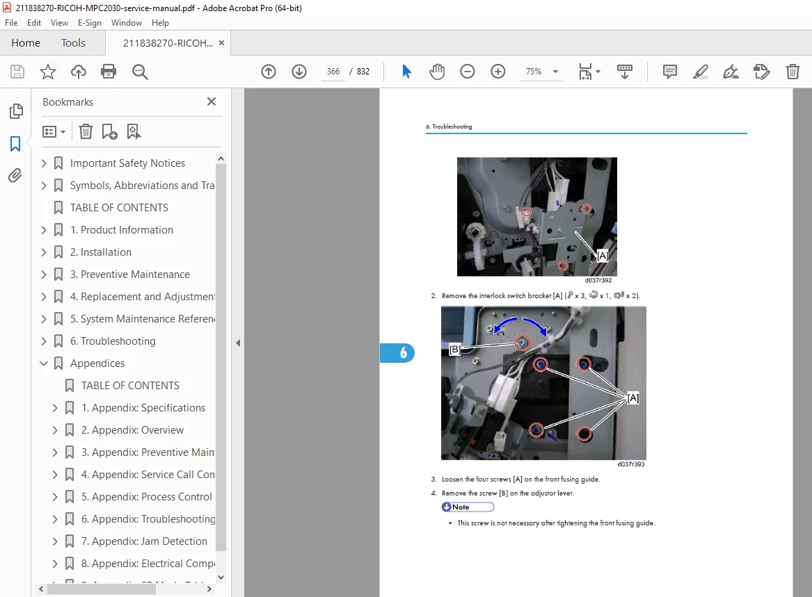
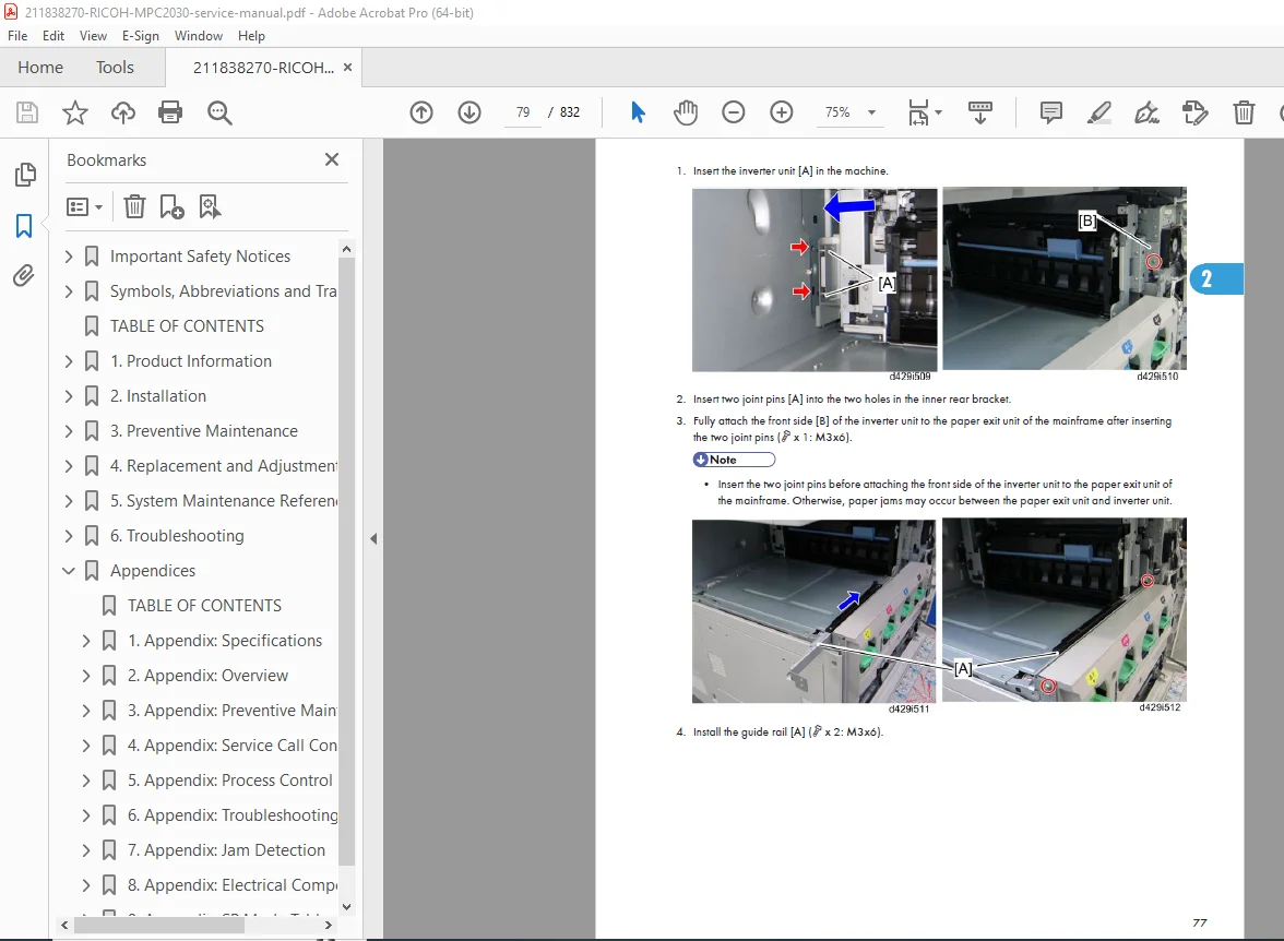
This is the complete official Ricoh MP C2030 / MP C2550 Service Manual PDF. This multi-hundred-page factory manual includes full disassembly, SPC tables, troubleshooting flowcharts, SC error codes, firmware update steps, mechanical and electrical operation theory, parts diagrams, maintenance procedures, and detailed wiring diagrams. Essential for technicians repairing the Ricoh MPC2030 series.
Description
Ricoh MP C2030 / MP C2550 Service Manual PDF DOWNLOAD(Service & Repair Guide)
Description
This is the complete factory Ricoh MP C2030 / MP C2550 Service Manual, the same master technical reference used by Ricoh-certified field engineers. It covers every aspect of installation, repair, diagnostics, troubleshooting, network configuration, replacement procedures, adjustments, firmware updates, and electrical/mechanical control theory.
The MP C2030 series is a high-performance color MFP, and this service manual provides everything necessary for advanced repair—including SC error codes, complete SP mode tables, image adjustment procedures, laser unit details, fusing system control, PCU maintenance, and network/system controller logic.
This is the most complete and technician-grade Ricoh MPC2030 service manual available.
Table of Contents
1. Safety Information
Safety labels & symbols
Laser safety
Electrical safety
Work precautions
Static-sensitive components
Warnings for hot surfaces, fusing system, and HV components
2. Product Overview
MP C2030 / C2550 model variations
Machine configuration
External and internal views
Operation panel layout
System specifications (print engine, scanning, copy speed, resolutions, color management)
Option compatibility
3. Installation
Site requirements
Power and environmental recommendations
Unpacking instructions
Transport & storage precautions
Installation workflow
Attaching options:
ARDF
Paper Bank
LCT
Finisher & Booklet Finisher
Fax unit
Browser unit
HDD
Network setup basics
Printer driver & controller preparation
4. Preventive Maintenance
PM schedule tables
Maintenance counter reset procedures
Consumables life (PCU, PCDU, transfer belt, fuser, ITB, toner units)
Lubrication points
Cleaning procedures
Deodorization filter replacement
Color calibration & registration
5. Replacement & Adjustment (Major Section)
5.1 Exterior / Frame
Front door
Left/Right/Rear covers
Duplex unit
Bypass tray
5.2 Lasers & Optics
Laser unit removal
Polygon mirror motor
Laser power detection
LD pitch adjustment
5.3 Image Processing Units
PCU:
Drum
Cleaning blade
Charge roller
Toner supply mechanism
Development Units (Process Color)
Cyan / Magenta / Yellow / Black
Developer replacement procedures
5.4 Paper Feed & Transport
Feed roller
Pickup roller
Registration roller
Transport rollers
Transfer belt / ITB unit
Transfer roller
Paper sensors
5.5 Fusing System
Fusing unit
Fusing belt
Pressure roller
Thermistors & thermostats
Fuser motor & gears
Temperature control flow
5.6 Scanning System
CCD unit
CIS alignment
Exposure unit
5.7 Finisher / SR790 & Booklet Finisher
Shift motor
Stapler unit
Booklet folding mechanism
6. Troubleshooting
6.1 Basic Troubleshooting
Jam removal flow diagrams
Sensor diagnostics
Motor failure detection
Color imbalance
6.2 SC Error Code List
Covers all Service Call Codes, including:
SC1xx: Lasers & optics
SC2xx: Motor errors
SC3xx: Paper transport & registration
SC4xx: Fusing temperature, thermistors
SC5xx: Controller board & firmware
SC6xx: HDD/NVRAM/SD card errors
SC7xx: Finisher / Booklet Finisher errors
6.3 Image Quality Troubleshooting
Color misregistration
Lines, spots, voids
Background and density issues
Voids in solid areas
Repetitive defect chart
6.4 Electrical & Mechanical Troubleshooting
Relay board diagnostics
PSU checks
HV block troubleshooting
Interface PCB checks
7. Service Program (SP Mode)
7.1 SP Mode Access
Entering service mode
Password-protected areas
Copier, Printer, Scanner SP categories
7.2 SP Mode Summary
Includes hundreds of SP items, such as:
SP1xxx: Copier operations
SP2xxx: Image process control
SP3xxx: Laser/optics adjustments
SP4xxx: Development control
SP5xxx: Paper feed
SP6xxx: Finisher
SP7xxx: Printer controller functions
SP8xxx: Network & system logs
SP9xxx: NVRAM initialization, counter resets
7.3 Test Patterns
Color registration
Grayscale
Dot test
Laser pitch test
Periodic color checks
8. Network & Controller
Printer controller architecture
NIC settings
IEEE1284 / USB / Ethernet details
PDL (PCL6/PS3) control flow
Fax unit initialization
Scanner network settings
Web Image Monitor service settings
9. Firmware & Software
Firmware update via SD card
Engine firmware vs. system firmware
NVRAM backup/restore
Language files
Printer engine SP firmware checks
10. Theory of Operation (Detailed)
10.1 Mechanical Theory
Paper feed timing
Registration synchronization
Transfer voltage control
Fusing heat profiles
Toner density detection logic
10.2 Electrical Theory
BCU (Basic Control Unit)
HV (High voltage)
SCU/MCU interactions
LD control logic
Controller board architecture
10.3 Color Image Process Theory
Color registration theory
Dither processing
Gamma correction
Density control loop (ID sensor feedback)
11. Wiring Diagrams
Complete fold-out wiring diagram
Controller board connections
HV block wiring
Sensor position map
Option wiring (Finisher / ARDF / LCT / Fax)
📁 File Details
| Field | Details |
|---|---|
| Manual Name | Ricoh MP C2030 / MP C2550 Service Manual |
| Models Covered | MPC2030, MPC2550 + options |
| PDF Version | Complete OEM Service Manual |
| Quality | Original factory PDF, text-searchable |
| Pages | 832 |