★ TRUSTED BY 321,897+ PROFESSIONALS WORLDWIDE
🏢
Trusted Business
Verified & Licensed
🛡️
Virus Free Files
100% Safe Downloads
🔒
Secure Payment
SSL Protected
⚡
Instant Delivery
Available Immediately
Sale!

Rolls-Royce Marine Hydraulic Deck Machinery Instruction Manual – Winches, Windlasses, Capstans & TOWCON Systems

Original price was: $39.95.Current price is: $24.95.

Complete Rolls-Royce Marine instruction manual for hydraulic deck machinery, covering windlass/mooring winches, tugger winches, secondary winches, towing/anchor handling winches, capstans, pump units, valves, TOWCON NT monitoring and remote control systems for the FELS SETAL 103 vessel.

⚡
Instant PDF Download
Available immediately
💾
Save to Your Device
Download & keep forever
🛡️
Antivirus Scanned
100% virus-free
🌍
Trusted Worldwide
175,000+ customers

Description

Rolls-Royce Marine Hydraulic Deck Machinery Instruction Manual

This comprehensive instruction manual covers the operation, maintenance, troubleshooting, and repair of Rolls-Royce Marine hydraulic deck machinery installed on the FELS SETAL 103 vessel (Hull 103, project A-8908). It spans 870 pages of technical documentation, including operating instructions, maintenance procedures, hydraulic schematics, wiring diagrams, parts lists, and assembly drawings for the complete winch system.

File Details

  • Manual Type: Marine Deck Machinery Instruction, Operation and Maintenance Manual
  • Brand: Rolls-Royce Marine AS, Dept. Deck Machinery – Brattvaag
  • Document Numbers: 389-094-00 Rev B, 815-015, 819-030GB, 414332, 324-247
  • Effective Date: 30.08.2004 (main parts list); various document revisions from 1993-2004
  • Language: English (with bilingual English/Norwegian sections)
  • Page Count: 870
  • File Format: PDF
  • Vessel: FELS SETAL 103 (Hull 103, project A-8908)
  • Equipment: Hydraulic deck machinery – winches, windlasses, capstans, pump units and control systems

Chapters Covered

The manual is structured into six main sections plus several standalone technical documents:

  • Section 1: Introduction – How to use the instruction manual, worldwide customer support
  • Section 2: Technical Specification – Operational conditions, workshop testing, counter flanges, special tools; detailed technical specifications for combined windlass/mooring winch type B842/W6315 and LBFMG63046; tugger winches type LAKMG63015; secondary winch type 50T (ALM63050U); towing/anchor handling winch type BSL300W/SL300W; capstans type CMC41 and CM 4185; pump units; oil cooler; full flow filters; expansion systems; remote control system; surface treatment
  • Section 3: Operating Instructions – Main system piping diagram and parts list; symbols for piping diagrams; operation and maintenance of hydraulic deck machinery; the hydraulic power transmission principle; lubrication instructions for open gears with Klüber lubricant; anchor dropping by dynamic braking; hydraulic pumps and motors; control system E12 for motors type M4185, M2202 and M1270; control valve type E2B; safety valve operation and adjustment; full flow filter cleaning; electric motor operation (ABB); remote control servo and electrical systems; TOWCON NT 200 operating instructions; WRC1021 operating instructions; tension control; DTL-NT user instructions; wireless data acquisition system; expansion system
  • Section 4: Maintenance Instructions – Hydraulic oil recommendations (ISO VG100); oil sampling procedure; filling instructions; drain/filling system; flushing; closure of open flange connections; general maintenance guidelines; lubrication charts for windlass, towing/anchor handling winch; lubrication system for large gear transmissions; gear wheel alignment; tooth engagement adjustment; welding procedures; flexible roller coupling; wireless torque/force measurement; winch alignment and pouring; mounting instructions for secondary winch, tugger winches, windlass; spooling of wire; wire rope fastener; chain wheel change; brake band support bearings; trouble shooting in general and trouble shooting lists; minor defects and repairs including stuffing arrangements for motors type M6300, MA10, M4185 & MA8
  • Section 5: Spare Parts – How to order spare parts; return of spare parts to RRM Brattvaag AS
  • Section 6: Drawings – Combined windlass/mooring winch assembly drawings; tugger winch drawings; secondary winch drawings; towing/anchor handling winch drawings (installation, main assembly, gearbox, brake, drum, chain wheel, bearing housing, chain stripper, emergency brake, hydraulic coupling gear, intermediate shaft, spooling gear, chain rollers, lubrication system); capstan drawings; F-valves (shock valve F48, lowering limit valve F92B/F92, intermediate piece F62B-1/F62C-2/F24, overflow valve F46B, pilot valve F122E, manifold F224, non-return valve F207/F239A/F239/F11, change over valve F204/F120C); pump units; oil cooler arrangement; full flow filters; expansion systems; remote control system diagrams including principle drawings, cable diagrams, cable lists, terminal diagrams, circuit diagrams for bridge panel interface, pump room interface, speed control interface, Towcon interface, servo unit, spooling gear; radio transmitter and receiver units
  • Lubrication Instruction for Open Gears with Klüber Lubricant (414332) – Preservation at factory and installation at yard; running-in period; operational lubrication; lubricant types and quantities; forced lubrication
  • Instruction for Use of Warning Signs (324-247) – Sign sizes, positioning guidelines on winches and pump units, responsibility for signs
  • TOWCON NT Monitoring and Control System Manual (815-015) – System layout, workstation, interface board, user controls, CRT monitor, touch screen, trackball operation, screen elements, digital displays, bargraphs, meters, sliders, popup menus, keypad, night color/dimmer, user menu, manual operations, automatic operations (pay-out, towing, hoist), using cable lifters, alarm handling, options including isolation transformer, UPS, slave monitor, additional workstations
  • Remote Control User Instruction (819-030GB) – Preparing operation, start of pumps, release brake, long time towing, limitation of maximum pull, connecting drums to motor units, rotate the winch, motor modes (1 cell, 2 cells, 3 cells), command change bridge and deck, tooth wheel lubrication, operating spooling device, emergency stop, emergency release, alarm lamps on control panel, overspeed protection, calibrating joystick for speed control, calibrating knob for tension control
  • Screw Pumps Operating and Maintenance Instructions (SN…ER Series) – General information, safety, transportation and storage, description, installation/mounting, start-up/shutdown, maintenance/repair, operating faults and remedial action, dismounting and mounting instructions, spare parts
  • Plate Heat Exchanger Manual – Principle and construction, function, mounting instructions, start-up operation stop and troubleshooting, maintenance and cleaning, spare parts and accessories
  • ABB Electric Motor Manual – Installation and commissioning, maintenance, increased safety motors EExe II, flameproof motors EExd, prolonged storing, surface treatment, painting repair instructions, spare parts

What This Manual Provides

This is a complete technical documentation package for the Rolls-Royce Marine hydraulic deck machinery installation on the FELS SETAL 103. It covers every major system on the vessel: the combined windlass/mooring winch, two tugger winches, secondary winches, the towing/anchor handling winch, and two capstans. Each system is documented with operating instructions, maintenance schedules, troubleshooting guides, and detailed assembly drawings.

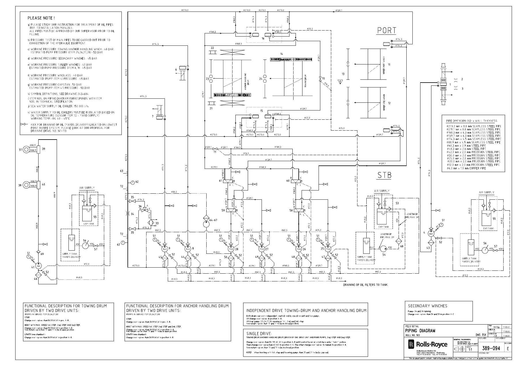
The manual includes complete hydraulic schematics showing the piping arrangement for the entire winch system, with port and starboard distribution, pump units, change-over valves, oil coolers, and expansion systems. Electrical documentation covers the remote control system, including bridge control panels, pump room interfaces, servo units, and the TOWCON NT monitoring and control system with touch screen operation.

For maintenance and repair, the manual provides step-by-step disassembly and reassembly instructions for major components: hydraulic motors, pumps, valves, brake assemblies, clutches, and gearboxes. It includes torque values, clearance specifications, adjustment procedures, and wear limits. The parts lists and assembly drawings allow identification and ordering of spare parts using Rolls-Royce Marine part numbers.

The TOWCON NT section is particularly detailed, covering both manual and automatic operations. Operators can learn how to use automatic pay-out, dynamic towing, and automatic hoist functions. The manual explains how to set wire length limits, tension alarms, pressure limits, and overspeed protection. It also covers the alarm system, trend monitoring, and print-out functions.

Safety information is integrated throughout, including warning signs, emergency stop and release procedures, brake operation precautions, and safe working practices around winches, chains, and wires.

Who This Manual Is For

This manual is essential for marine engineers, deck officers, winch operators, and maintenance technicians working with Rolls-Royce hydraulic deck machinery. It is also valuable for vessel superintendents and technical managers responsible for maintaining anchor handling and towing equipment. The level of detail makes it suitable for both experienced technicians familiar with the equipment and those new to Rolls-Royce Brattvaag winch systems.

Why This Manual Matters

Hydraulic deck machinery operates under extreme loads and in harsh marine environments. Incorrect operation or maintenance can lead to equipment failure, safety incidents, or damage to the vessel. The procedures and specifications in this manual ensure that winch systems are operated within safe limits, maintained correctly, and repaired to the manufacturer’s standards. The troubleshooting guides help identify and resolve faults quickly, minimizing downtime during critical anchor handling or towing operations.

Complete PDF Bookmark Tree

Complete Bookmarks

The complete bookmarks in the “Rolls-Royce Marine Hydraulic Deck Machinery Instruction Manual – Winches, Windlasses, Capstans & TOWCON Systems” are as follows:

warning
1. Introduction
Introduction 243-682
Example how to use the instruction manual 243-683
Questionnaire for instruction manual 243-680
Table of contents
Worldwide customer support.pdf
2. Technical specification
Technical specification
3. Operating Instuctions
Instruction for use of warning signs 324-247
Piping diagram 389-094
389-094-00.pdf
Important Items
Symbols for piping diagram 331-093
Operation and maintenance of Hydraulic Deck Machinery UBR 21/92
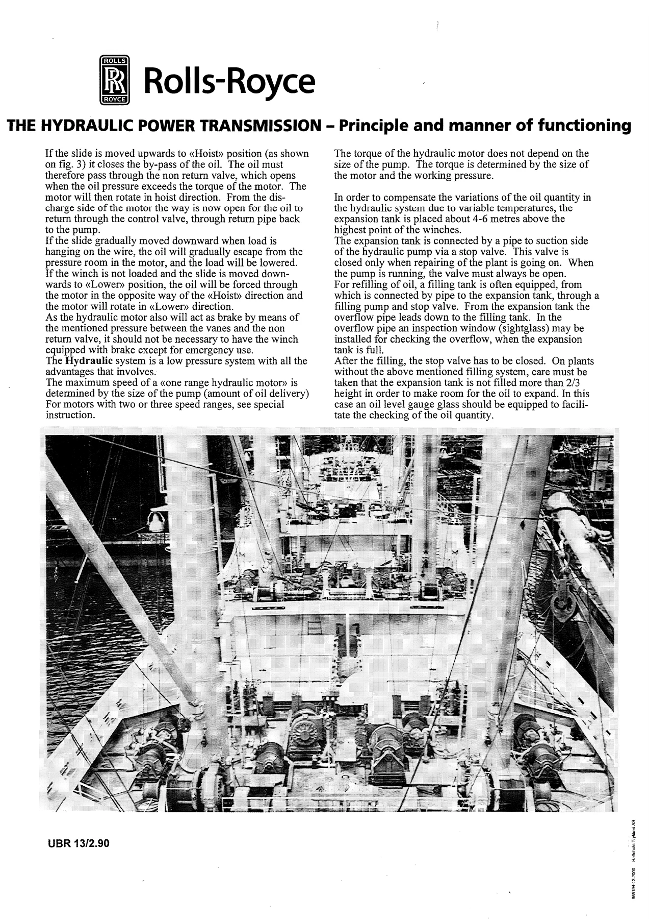
The Hydraulic Power Transmission UBR 13/90
Lubrication instruction for open gears with Klüber lubricant 414332p. 40
Instruction lubrication pump secondary winch 392-677-23
Instruction lubrication pump, anchor handling / towing winch 392-677-01
Anchor dropping by means of dynamic breaking 209-673
The Hydraulic pumps and motors UBR 12/92
Control System type E12 GB 22/89
Control System type E2B UBR 104/73
Safety Valve UBR 23/89
Full Flow Filter UBR 123/81
Service Instruction for three-phase motors ABB
Instruction for plate heat exchanger APV
Operating and Maintenance Instructions Allweiler
Principle drawing, servo system 391-066
Principle drawing, spooling gear 391-067
Principle drawing, spooling gear 403-171p. 165
Main Parts List 391-068-00
Cable diagram 392-389
Cable diagram, monitoring system 392-436
Cable list 1 392-416
Cable list 2 392-417
Cable list 3 392-418
Cable list 4 392-419
Operating Instruction “Towcon NT 200” 815-015p. 173
Operating Instruction WRC1021 812-180GB
Operating Instruction Tension Control 814-269
Microsoft Word – 814-156.pdfUser Instructions for DTL –NT 814-156
User Manual Wireless Data Acquisition System 510132
User Instruction Remote Control 819-030GBp. 307
2/17p. 308
3/17p. 309
4/17p. 310
5/17p. 311
6/17p. 312
7/17p. 313
8/17p. 314
9/17p. 315
10/17p. 316
11/17p. 317
12/17p. 318
13/17p. 319
14/17p. 320
15/17p. 321
16/17p. 322
17/17p. 323
Level regulated expansion system 225-166-07
Level regulated expansion system 127-427
Level regulated expansion system 240-330
4. Maintenace Instructions
Hydraulic Oil ISO VG100
Lubricant recommendation for RRM Brattvaag equipment 215-152
Oil sampling procedure 253-035
Instruction for filling of hydraulic oil 077-436
Proposal for drain- / filling system 161-113
Flushing 138-222
Flushing 138-223
Closure of open flange connections 164-146
Maintenance in general 812-469
Guidelines for maintenance and inspection routines merchant vessels 812-474
Instruction for lubrication of winches – general 812-471
Lubrication chart for windlass 269-206
Lubrication chart for towing / anchor handling winch 213897
Instruction lubrication system for large gear transmissions (1-10) 413464
Lubrication instruction for open gears with Klüber lubricant 414332p. 356
2/6p. 357
3/6p. 358
4/6p. 359
5/6p. 360
6/6p. 361
Klübersynthp. 362
Klübersynthp. 363
Klübersynthp. 364
Klübersynthp. 365
Klübersynthp. 366
Klübersynthp. 367
Klübersynthp. 368
Klübersynthp. 369
Instruction lubrication pump, secondary winch 392-677-23
Instruction lubrication pump, anchor handling / towing winch 392-677-01
Frequency Inverter Fuji FVR-E9S 413574
Full Flow Filter UBR 123/81
Wirecoiling, start position 203-010
Lifting instruction for towing / anchor handling winch 16851p. 376
Mounting instruction for towing / anchor handling winch 16850p. 377
Gear wheel alignment for towing / anchor handling winch 314421
Adjusting and control of tooth engagement between gear wheel and pinion 412857
Welding procedure WPSH-184
Welding procedure WPSH-165
Flexible roller coupling 1 21389
Installation drawing wireless measurement of torque/force 214124
Installation drawing wireless measurement of torque/force 213428
Positioning of intermediate piece with load cells 314449
Procedure for aligning and pouring of winch 412912
Mounting instruction secondary winch / tugger winch 44361
Tightening torque foundation bolts 49650
Mounting instruction windlass 392-063GB
Mounting instruction tugger winches 311-391
Spooling of wire 413802
Wire rope fastener instruction 28065A
Wire fastening device 213901
Adjustment instruction for 2-position coupling gear 413706
Instruction for hydraulic spooling devices 413742
Instruction for change of chain wheel (1-9) 412582
Instruction for brake band support bearings 412176
Support bearing for brake band 35991A
Trouble shooting in general 811-789
Trouble shooting list UBR 21/92
Stuffing arrangement for motors type M6300, MA10, M4185 & MA8 127-241
Stuffing arrangement for motors 119-365
119-365-AA.pdf
119-365-AB.pdf
119-365-CB.pdf
5. Spare Parts
How to order spare parts 812-012
Return of spare parts to RRM Brattvaag AS 812-011
6 Drawings
6.0 Drawing List
6.1 Combined Windlass/ Mooring winch.
Combined windlass / mooring winch type B842/W6315 367-352
367A352-00
Combined windlass / mooring winch type LBFMG63046 368-006p. 440
368A006-01
Motor / valve arrangement 324-286
324A286-01
Motor / shaft type MG63SAA 367-383
367a383-00
Motor type MG6300-A 111-132p. 446
111-132-
Cable lifter 141-182
141A182-14
Brake arrangement 189-010p. 450
189-010-01
Brake arrangement 261-049p. 452
261A049-00
Brake screw 215-032p. 454
215-032-
Bearing block 281-429p. 456
281A429-00.pdf
Bearing block 364-367p. 458
364A367-03
Coupling arrangement 380-345p. 460
380-345-01
380-345-02
Coupling arrangement 393-286p. 463
393-286-00
393-286-01
Operating valve type E21 317-056p. 466
317-056-03.pdf
Top 227-147p. 468
227-147-.pdf
Return device 229-168p. 470
229-168-.pdf
Distributing valve 231-105p. 472
231-105-.pdf
Chain stopper 195-050
6.2 Tugger winches
Tugger winch type LAKMG63015 390-712p. 475
390-712-00
Tugger winch type LAKMG63015 390-862p. 477
390-862-00
Tugger winch type LAKMG63015 390-713p. 479
390-713-00.pdf
Tugger winch type LAKMG63015 390-861p. 481
390-861-00
Motor / valve arrangement 390-872p. 483
390-872-00
Motor / valve arrangement 390-873p. 485
390-873-00
Motor / shaft type MG63.SBL 159-181p. 487
159-181-
Motor / shaft type MG63.SBR 159-180p. 489
159-180-
Motor type MG6300-B 111-131p. 491
111-131-
Brake arrangement 148-398p. 493
148-398-
Brake screw 108-345p. 495
108-345-
Bearing block 281-139p. 497
281-139-
Operating valve type E21 317-056p. 499
317-055-22
Distributing valve 231-105p. 501
231-105-.pdf
Return device 234-005p. 503
234-005-
Top 388-859p. 505
388-859-00
Secondary cylinder 113-063
113-063-05.pdf
6.3 Secondary Winches
Secondary winch type 50T 213472H
Secondary winch type 50T 213622H
Secondary winch type 50T213472V
Secondary winch type 50T213622V
Spooling gear 17696p. 514
Bearing house with spherical roller bearing 211255
Bearing with SKF roller bearing 37089
Pump with tank 210616
Brake 16968
Brake cylinder 13491
Lubrication wheel 15518
Lubrication system 15838
Instruction lubrication pump secondary winch 392-677-23
Motor / valve arrangement 392-379
392-379-00
Motor / valve arrangement 392-378
392-378-00.pdf
Motor / shaft type GT63SBR 283-318p. 527
283-318-.pdf
Motor / shaft type GT63SBL 287-032p. 529
287-032-.pdf
Motor type M6300T-B 129-170p. 531
129-170-.pdf
Proximity switch 164-325p. 533
164-325
Operating valve type E12ABJC3C3TB 131-086.pdf
750-042-79.pdf
750-042-80.pdf
Inlet section 148-176p. 538
148-176-01.pdf
Valve housing 301-014p. 540
301-014-
Slide 301-011p. 542
301-011-
Top 388-716p. 544
388-716-00
Secondary cylinder 113-063
113-063-03
6.4 Towing / Anchor Handling Winch
Towing / anchor handling winch type BSL300W/SL300W, installation dawing 15806
Towing / anchor handling winch type BSL300W/SL300W, main assembly drawing 16570
Control of gearwheel backlash and alignment 314421
Lubrication chart 213897
Positioning of intermediate piece with load cells 314449
Brake 15233
Drum arrangement 16801
Chain wheel arrangement 211132
Tool for mounting / dismounting of chain wheel 311999
Instruction for change of chain wheel (1-9) 412582
Bearing housing 15396
Chain stripper arrangement 16901
Pump unit for manual operation of hydraulic coupling actuators 310112
Emergency brake unit 13200
Drum arrangement 16802
Bearing housing with spherical roller bearing 29992
Hydraulic coupling gear 29246
Intermediate shaft arrangement 16882
Bearing with spherical roller bearing 212228
Bearing housing with spherical roller bearing 29423
Brake 15234
Brake cylinder 28663
Gearbox with flexible roller coupling and pipe arrangement, port side 213624
Flexible roller coupling 213891
Wireless measurement of torque/force, assembly drawing 16244
Wireless measurement of torque/force, mounting of guard for power antenna 213428
Gearbox, assembly 15958V
Gearbox, port side 15958H
25T spooling gear, deck arrangement 16571
25T spooling gear, deck arrangement 16573
25T spooling gear, deck arrangement 16572
Roller 211159
Roller 214052
Adjustable chain roller arrangement 212164
Bearing house with SKF-spherical roller bearing 212163
Chain roller arrangement 212160
Lubrication system 15615
Lubricating wheel 15355
Automatic lubrication pump 15590
Instruction lubrication pump 392-677-01
Frequency inverter Fuji FVR-E9S 413574
Motor / valve arrangement 392-068
392-068-00
Motor / valve arrangement 392-069
392-069-00.pdf
Motor / shaft type XC63SBR 367-398p. 605
367-398-00.pdf
Motor / shaft type XC63SBR 367-397p. 607
367-397-00.pdf
Motor type MXC6300-A 362-184-01p. 609
362-184-01
Solenoid valve type ND6 222-170p. 611
222-170
Control valve 131-086
Control valve type E12ABJM3N1AB/ 750-042-03
E12ABJM3N1TB/ 750-042-12
E12ABJN1M3AA/ 750-042-04
E12ABJN1M3TA 750-042-11
Top 111-013p. 618
111-013-01.pdf
Top 388-716p. 620
388-716-00
Slide 301-011p. 623
301-011-
Valve housing 301-014p. 625
301-014-
Inlet section 376-107p. 627
376-107-00
Inlet section 376-113p. 629
376-113-00
Secondary cylinder 113-063
113-063-03
6.5 Capstans
Capstan type CMC41 324-566p. 633
324-566-00.pdf
Capstan type CMC41 168-128p. 635
168-128-.pdf
Capstan type CMC41 324-568p. 637
324-568-00.pdf
Capstan type CMC41 168-127p. 639
168-127-.pdf
Motor / shaft type M4185/C-BR 141-292p. 641
141-292-01.pdf
Motor / shaft type MC41SBL 141-289p. 643
141-289-.pdf
Motor M4185/C-B 183-023-01
183-023-01.pdf
Control valve type E2B 114-024-01p. 647
114-024-01.pdf
6.6 F-Valves
Shock valve type F48 112-057p. 650
112-057-.pdf
Lowering limit valve type F92B 112-119p. 652
112-119-.pdf
Intermediate piece type F62B-1 114-014p. 654
114-014-
Intermediate piece type F62C-2 109-068p. 656
109-068-.pdf
Overflow valve type F46B 130-241p. 658
130-241-
Pilot valve type F122E 220-379p. 660
220-379-
Manifold type F224 269-006p. 662
269-006-.pdf
Lowering limit valve type F92 112-118p. 664
112-118-
Non return valve type F207 214-060p. 666
214-060-
Non return valve type F239A 370-118p. 668
370-118-00
Intermediate piece type F24 108-467p. 670
108-467-.pdf
Change over valve type F204/F120C 178-367p. 672
178-367-02
Non return valve type F11 112-047p. 674
112-047-
Non return valve type F239 323-006
323-006-17.pdf
6.7 Pump units
Pump unit type PV GS 660-46 266-274p. 678
266A274-00
Pump unit type GS 660-46 217-131p. 680
217a131-00
Safety valve type F70A 111-192p. 682
111-192-.pdf
Non return valve type F207 214-060p. 684
214-060-.pdf
Starter 309-148
Pump unit type PV GS 940-46 217-117p. 687
217-117-
Pump type GS 940-46 237-166p. 689
237-166-
Starter 309-156
Pump unit type PV GS 1700-46 348-063p. 692
348-063-05.pdf
Pump type GS 1700-46 217-123
217-123-10.pdf
Safety valve type F115L 225-146
225-146-09
Non return valve type F216 214-061p. 698
214-061-.pdf
Starter 309-172-03
Pump unit type PV SNS 280-46 318-061p. 701
318-061-
Safety valve type F70A 111-193p. 703
111-193-
6.8 Oil cooler Arrangement
Oil Cooler 812-257
Throttle valve 167-352p. 708
167-352-
Sluice valve 130-336p. 710
130-336-03.pdf
3-way valve 324-079p. 712
324-079-00.pdf
6.9 Full flow filters
Full flow filter type N7A 158-180p. 714
158-180-.pdf
Full flow filter type N8A 163-123p. 716
163-123-.pdf
6.10 Expansion system
Expansion system 225-166
225-166-07.pdf
Expansion tank 225-164
225-164-06.pdf
Expansion tank 196-095
196-095-
Pump unit 309-242p. 724
309-242-.pdf
Starter 309-241p. 726
Divider kit 226-208p. 727
226-208
Expansion system 240-330p. 729
240-330-.pdf
Expansion tank 216-084
216-084-.pdf
Filling pump 324-326p. 733
324-326-00.pdf
6.11 Oil Filter Arrangement
Principle drawing 321-307p. 735
321-307-
Filter arrangement 227-122-01p. 737
227-122-01
Pump unit 309-242-01p. 739
309-242-01
Starter 321-306
6.12 Remote Control System
Principle drawing (servo system) 391-066
Principle drawing (spooling gear) 391-067
Principle drawing (spooling gear) 403-171p. 744
Lubrication system, towing/anchor handling winch 15615
Lubrication system, secondary winch 15838
Terminal diagram 392-850
Motor / valve arrangement towing / anchor handling winch 392-068
Motor / valve arrangement towing / anchor handling winch 392-069
Motor / valve arrangement secondary winch 392-378
Motor / valve arrangement secondary winch 392-379
Parts list remote control 389-073-00
Cable diagram 392-389
Power consumption list 392-415
Cable list 1 392-416
Cable list 2 392-417
Cable list 3 392-418
Cable list 4 392-419
Terminal diagram 1 394-454
Terminal diagram 2 394-455
Terminal diagram 3 394-456
Controller DTL 318-106
318-106-00.pdf
Control box – DTL monitoring unit 243-326
Control box, on/off 319-306
319-306-00.pdf
Control box 367-225
367-225-00
Control panel + BCP1 392-388
392-388-00.pdf
Control panel 403-440p. 771
Control panel + BCP2 392-429
392-429-00.pdf
Control panel + BCP2 392-430
392-430-00.pdf
Bridge panel interface + BP1 392-431
392-431-00.pdf
Circuit diagram 1, + BPI 394-410
Circuit diagram 2, + BPI 394-411
Circuit diagram 3, + BPI 394-412
Circuit diagram 4, + BPI 394-413
Circuit diagram 5, + BPI 394-414
Circuit diagram 6, + BPI 394-415
Circuit diagram 7, + BPI 394-416
Circuit diagram 8, + BPI 394-417
Circuit diagram 9, + BPI 394-418
Circuit diagram 10, + BPI 394-419
Circuit diagram 11, + BPI 394-420
Circuit diagram 12, + BPI 394-421
Circuit diagram 13, + BPI 394-422
Pump room interface + PRI 392-432
392-432-00.pdf
Circuit diagram 1, + PRI 394-423
Circuit diagram 2, + PRI 394-424
Circuit diagram 3, + PRI 394-425
Circuit diagram 4, + PRI 394-426
Circuit diagram 5, + PRI 394-427
Interface for PLC 318-144
318-144-00
Interface for PLC 318-145
318-145-00
Speed control interface 392-433
392-433-00.pdf
Circuit diagram 1, + SCI 394-428
Circuit diagram 2, + SCI 394-429
Circuit diagram 3, + SCI 394-430
Circuit diagram 4, + SCI 394-431
Circuit diagram 5, + SCI 394-432
Circuit diagram 6, + SCI 394-433
Circuit diagram 7, + SCI 394-434
Circuit diagram 8, + SCI 394-435
Circuit diagram 9, + SCI 394-436
Circuit diagram 10, + SCI 394-437
Towcon interface + TOI 392-434
392-434-00.pdf
Circuit diagram 1, + TOI 394-438
Circuit diagram 2, + TOI 394-439
Circuit diagram 3, + TOI 394-440
Circuit diagram 4, + TOI 394-441
Circuit diagram 5, + TOI 394-442
Circuit diagram 6, + TOI 394-443
Circuit diagram 7, + TOI 394-444
Circuit diagram 8, + TOI 394-445
Circuit diagram 9, + TOI 394-446
Circuit diagram 10, + TOI 394-447
Circuit diagram 11, + TOI 394-448
Circuit diagram 12, + TOI 394-449
Circuit diagram 13, + TOI 394-450
Circuit diagram 14, + TOI 394-451
Mounting instruction N0 394-452
Mounting instruction N10 394-453
Monitoring system 392-436
392-436-00.pdf
Control system 393-498-00
Radio transmitter + RT1 393-499
Radio transmitter + RT1 & RT2 393-504
Radio receiver + RR1 393-500
Radio transmitter + RT2 393-502
Radio receiver + RR2 393-503
Parts list remote control 391-068-00
Servo pump unit 391-065
391-065-00.pdf
Servo system 391-066
Servo system 391-067
Starter 391-063
Circuit diagram 1 + SU1 392-576p. 847
Circuit diagram 2 + SU1 392-577p. 848
Circuit diagram 3 + SU1 392-578p. 849
Circuit diagram 4 + SU1 392-579p. 850
Servo pump unit 391-064
391-064-00.pdf
Parts list servo unit 818-581
Valve panel 403-169p. 855
Junction box 404-609p. 856
Shock valve 396-208p. 857
Interface terminal + SU2 392-435p. 858
392-435-00.pdf
Circuit diagram 1 + SU2 392-541p. 860
Circuit diagram 2 + SU2 392-542p. 861
Circuit diagram 3 + SU2 392-543p. 862
Circuit diagram 4 + SU2 392-544p. 863
Circuit diagram 5 + SU2 392-545p. 864
Circuit diagram 6 + SU2 392-546p. 865
Circuit diagram 7 + SU2 392-547p. 866
Circuit diagram 8 + SU2 392-548p. 867
Circuit diagram 9 + SU2 392-549p. 868
Circuit diagram 10 + SU2 392-550p. 869
Circuit diagram 2 +SU3p. 870

Delivery

IMAGES PREVIEW

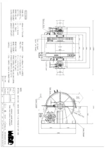
Rolls-Royce Marine Hydraulic Deck Machinery Instruction Manual - Winches, Windlasses, Capstans & TOWCON Systems — PDF page 60 preview
Rolls-Royce Marine Hydraulic Deck Machinery Instruction Manual - Winches, Windlasses, Capstans & TOWCON Systems — PDF page 47 preview
Rolls-Royce Marine Hydraulic Deck Machinery Instruction Manual - Winches, Windlasses, Capstans & TOWCON Systems — PDF page 99 preview

This Rolls-Royce Marine hydraulic deck machinery instruction manual is delivered as an instant PDF download after purchase. There is no shipping, no waiting for a physical book, and no risk of a damaged or lost package. The PDF can be viewed on any computer, tablet, or smartphone. Individual pages can be printed for use in the engine room or at the winch control station. The searchable text allows quick location of specific procedures, part numbers, or specifications.
Reviews

There are no reviews yet.

Be the first to review “Rolls-Royce Marine Hydraulic Deck Machinery Instruction Manual – Winches, Windlasses, Capstans & TOWCON Systems”

What Our Customers Say

★★★★★ Live reviews from customers
Loading customer reviews...
0
    0
    Your Cart
    Your cart is emptyReturn to Shop
    🛒
    Recently Purchased
    🕒 verified order