
Rolls-Royce Rauma Brattvaag Deck Machinery Installation Manual – Winch, Windlass, Towing & Anchor Handling Systems PDF
Original price was: $39.95.$24.95Current price is: $24.95.
Complete 381-page Rolls-Royce Rauma Brattvaag deck machinery installation manual covering windlass/mooring winches, tugger winches, towing and anchor handling winches, capstans, spooling gear, pump units, servo and electrical systems, piping, flushing, commissioning and oil specification for the Aker Yards Brattvaag installation (plant no. OSSD/05/0684 – A09774).
Description
This Rolls-Royce Rauma Brattvaag Deck Machinery Installation Manual is the complete yard installation document for a full deck machinery winch package supplied for Aker Yards Brattvaag, Newbuilding No. 119, Revision 1, plant number OSSD/05/0684 – A09774, dated 13.02.2008. It is the reference used by the installing yard, the commissioning supervisor and the vessel’s technical team to install, pipe, wire, flush, commission and hand over the hydraulic winch systems before the vessel enters service. Everything in it assumes a technician working on real hardware – the drawings, piping diagrams, dimension sheets, hydraulic schematics and commissioning checklists are the same documents issued with the machinery itself.
File Details
- Manual type: Installation Manual (deck machinery / hydraulic winch systems)
- Brand: Rolls-Royce Marine AS, Dept. Deck Machinery – Brattvaag (Rauma Brattvaag)
- Project: Aker Yards Brattvaag, Newbuilding No. 119, Revision 1
- Plant number: OSSD/05/0684 – A09774
- Date: 13.02.2008
- Language: English (with the introductory section presented bilingually in English and Norwegian)
- Pages: 381
- Format: PDF
What This Rolls-Royce Rauma Brattvaag Installation Manual Contains
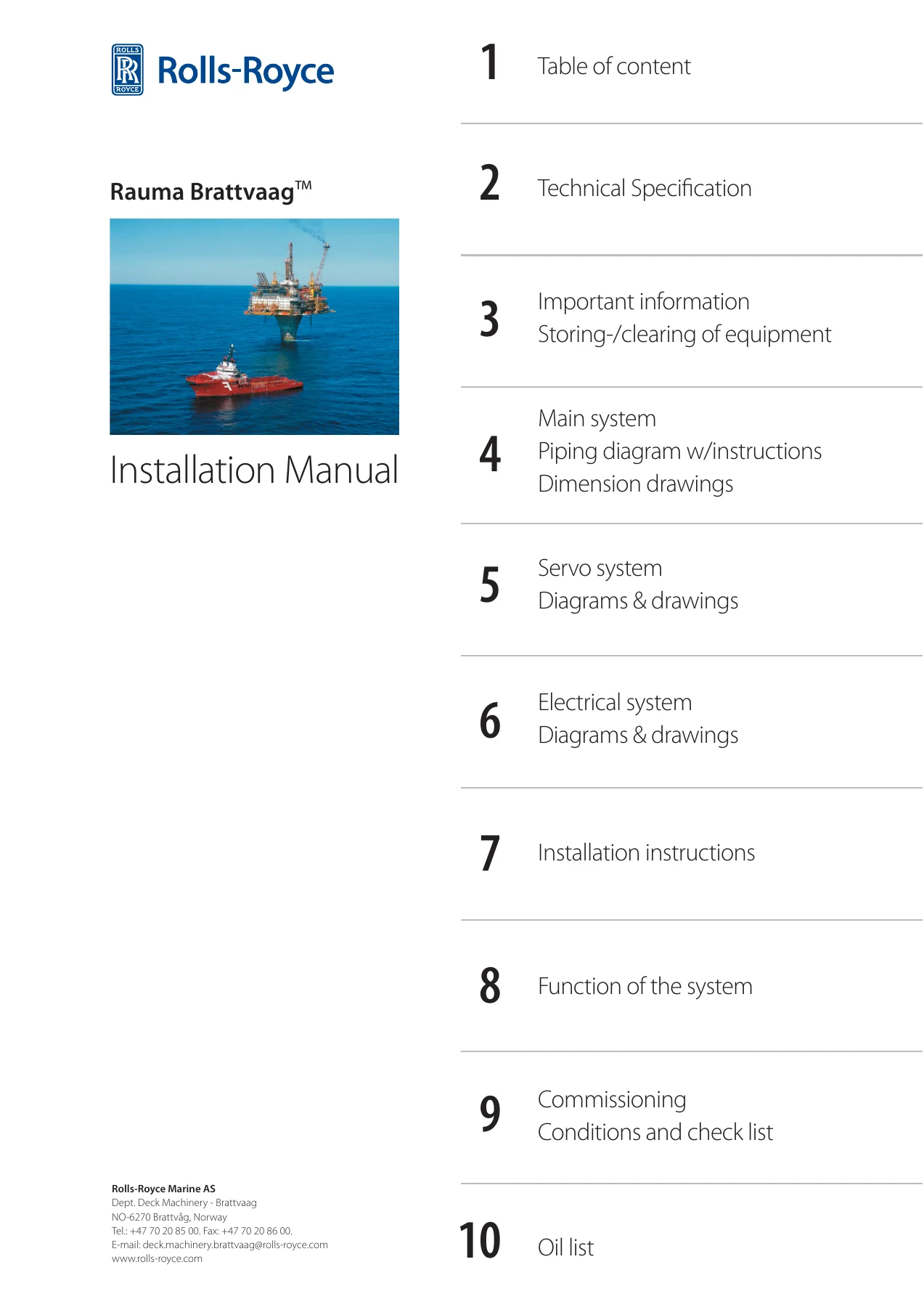
Unlike a generic winch leaflet, this is a full yard installation package. It opens with the Rauma Brattvaag introduction and revision-control system, then moves straight into the technical specification for every unit in the scope of supply – windlass/mooring winches, chain stoppers, tugger winches, the towing/anchor handling winch, capstans, spooling gear, hydraulic pump units and their starters. From there the manual works through the main hydraulic system, servo system and electrical system, each with its own diagrams and drawings, before finishing with the installation procedures, the function descriptions, the pre-commissioning checklist and the oil specification.
The piping, welding and flushing sections are unusually thorough. They cover closure of open flange connections, filling hydraulic oil, first start of a hydraulic winch system, a proposed drain/refill arrangement, recommended pipe sizes, pipe laying for the main system, welding, cleaning and inspection of hydraulic piping, treatment of main and servo pipe systems, leakage and pressure testing, and filter-net flushing of the UBR full-flow filters. The same degree of detail is applied to the servo system (principal drawings, pump units, terminal diagrams, interface cabinets) and the electrical system (cable diagrams, power consumption lists, terminal diagrams, circuit diagrams, portable radio control transmitters and receivers).
Chapters Covered
- 1. Table of Content – Introduction – Installation manual introduction, revisions of the installation manual, questionnaire, worldwide customer support
- 2. Technical Specification – General technical information, operational conditions, workshop testing, counter flanges, technical specification of all winch units, motor and pump data, surface treatment grades
- 3. Important Information – Warning and cautions, storing at yard, incoming inspection, storage-period maintenance, cleaning and preparation of equipment
- 4. Main System – Piping diagram with instructions, main part list, important items, symbols for piping diagram, closure of open flange connections, instructions for filling hydraulic oil, starting a hydraulic winch system, draining system proposal, recommended pipe size, pipe laying, welding/cleaning/inspection, treatment of pipe systems for hydraulic plants (main and servo pipes), leakage and pressure testing, flushing of pipes (main system), windlass/mooring winch installations, chain stoppers, pump units, starters, circuit diagrams, tugger winch installations, towing/anchor handling winch, spooling gear, capstan units, expansion systems, filters, valves, oil coolers
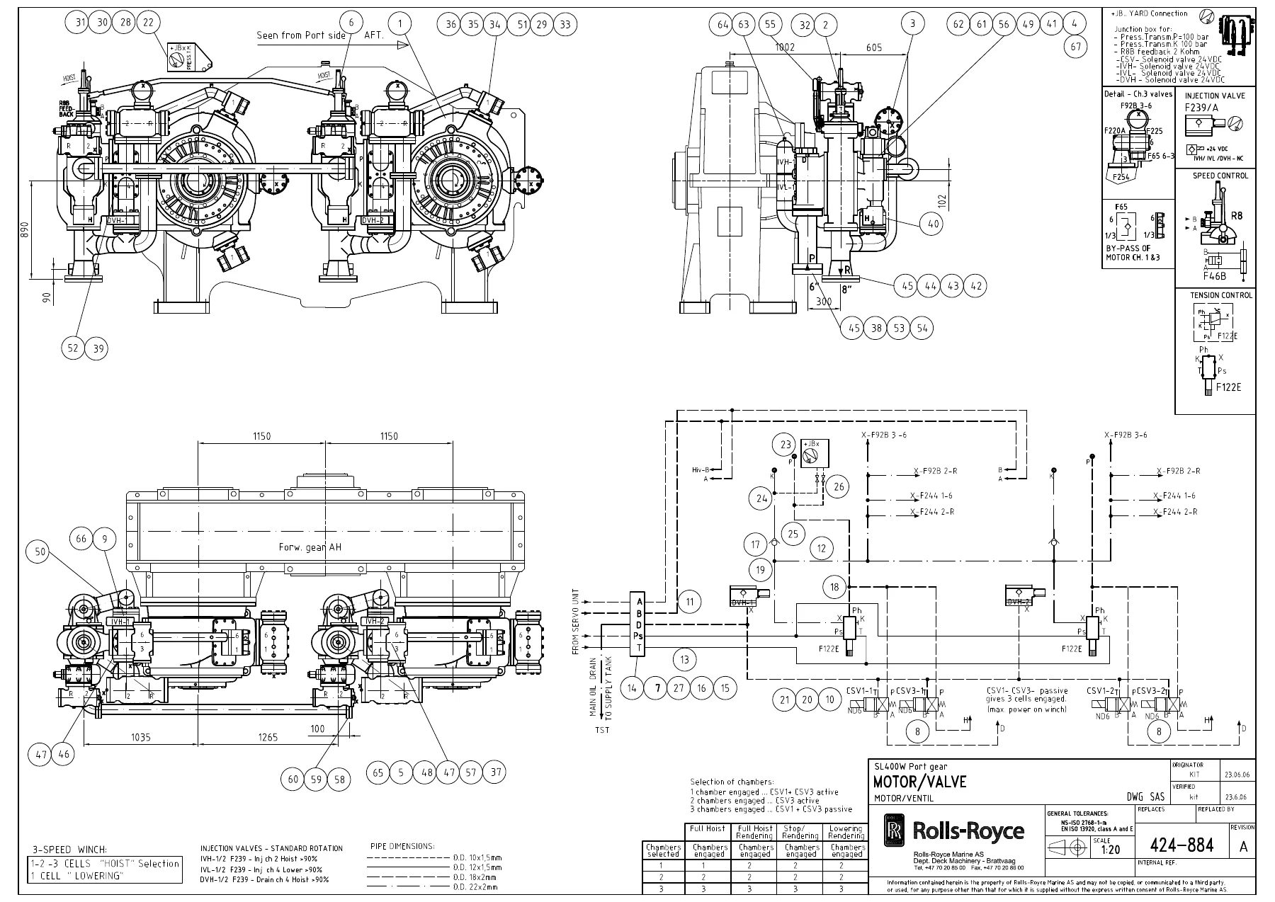
- 5. Servo System – Parts list for remote control, terminal diagram, principle drawings for main system, windlass and capstan servo systems, servo pump units, circuit diagrams, interface cabinets, motor/valve arrangement for towing/anchor handling winch, junction box
- 6. Electrical System – Parts list for remote control electronics, electrical installation requirements, cable diagram, cable list, power consumption list, terminal diagrams, electronic control system, control panel, bridge interface, operator chair, winch control chair, main control cabinet, towing control cabinet, oil control cabinet, power supply, portable control systems for main winches, tugger winches, capstans and windlasses, radio transmitters and receivers
- 7. Installation Instructions – Chain and chain release, level regulated expansion system, screw torque, mounting and lubrication instructions for windlass, tugger winch and towing/anchor handling winch, welding procedures, lifting instructions, gear wheel backlash and alignment control, brake band support bearings, wire fastening device, tooth engagement adjustment, 2-position coupling gear, wire spooling, open gear lubrication, flexible roller coupling, chain-driven spooling device lubrication, brake lubrication and adjustment, bushing lubrication, roller bearing lubrication, emergency brake, alignment of gear transmissions, prestressed force and tightening torque table, filter net user instruction
- 8. Function of the Systems – The hydraulic power transmission, hydraulic pumps and motors, safety valve, full flow filter, control valve types E12/E14 for motors MA8, E2B, E17-U for motors MA10, oil coolers, operation and maintenance of hydraulic deck machinery, troubleshooting in general
- 9. Commissioning: Conditions and Check List – General conditions for commissioning and final inspection, pre-commissioning checklist
- 10. Oil List – Recommended hydraulic and gear lubricants by brand and type, oil sampling and acceptance criteria
Equipment and Systems Covered
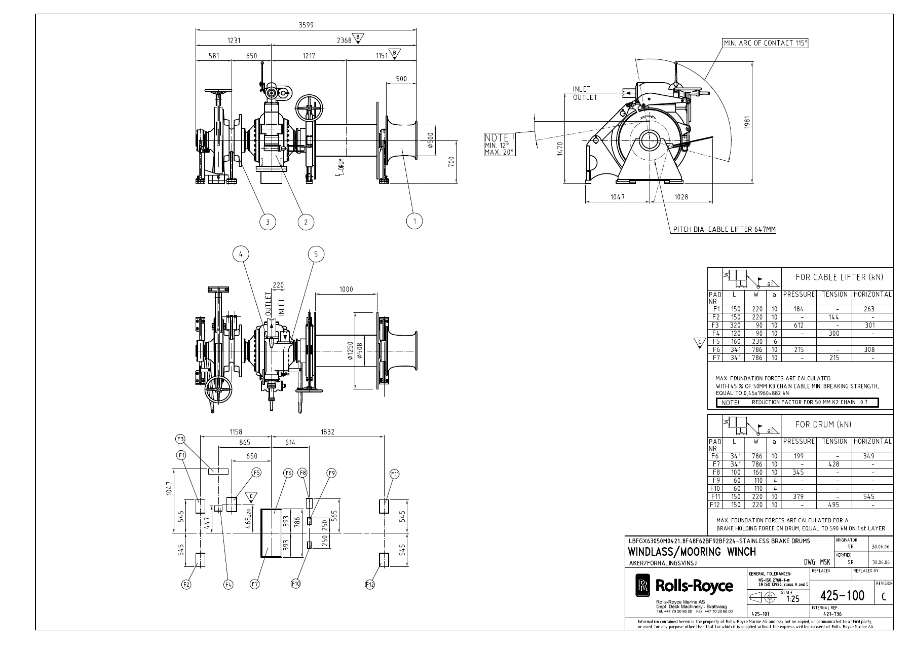
The installation manual is written around the specific machinery list for this project, and covers the combined windlass / mooring winches type BFM63.046 (drawings 425-100 and 425-101) with declutchable cable lifter, drum and warping end, 50 mm U3 stud link chain; chain stoppers NP4 of roller type; the Brattvaag pump units PH SNF 280-46 and PV GS 1300-44 with their ABB motors and Star-Delta starters; the tugger winches LAKMX41016; the waterfall-type towing / anchor handling winch SL400W-3T (drawing 16928) with its 400-tonne towing drums, anchor handling drum, cable lifters, chain strippers and chain rollers; the hydraulic / remote controlled spooling gears for the anchor handling drum and towing drums; the capstans type CX 4115; the large PV GS 3600-46 pump units for the main winch; and the expansion, cooling, filtration and valve arrangements that tie the system together. Servo pump units for the towing/anchor handling winch, windlass and capstans are covered, along with the Brattvaag Towcon control and monitoring system.
Piping, Welding and Hydraulic Installation Support
Because hydraulic cleanliness is what decides whether a deck machinery installation survives its first year, this Rauma Brattvaag installation manual spends a lot of pages on it. You get the recommended pipe sizes and wall thicknesses, the pipe-laying rules including expansion bends and clamp spacing, the welding procedure with TIG root and MIG fill, flange welding sequences to avoid distortion, mechanical cleaning of pipes and flanges, pickling and neutralisation, internal corrosion protection, and the handling and storage of finished pipe sections. The leakage and pressure testing instruction and the flushing instruction (with and without filter cloth, using Reynolds number targets and 50-60 degree oil temperature) give you the acceptance criteria the commissioning engineer will apply.
Servo and Electrical Documentation
The servo system chapters contain the parts list for the remote control, terminal diagrams, principle drawings for the main system, windlass and capstan servo units, and the servo pump unit assemblies with their solenoid valve blocks and pressure switches. The electrical system chapters supply the electrical installation requirements with the EMC rules, cable selection for power, control, signal and bus cables, cable and power consumption lists, terminal diagrams and circuit diagrams for the starters – including the Y/D starter circuits for the 79 kW, 99 kW, 165 kW and 475 kW pump unit motors and the 2.8 kW expansion pump starter – plus the portable radio control systems for main winches, tugger winches, capstans and windlasses.
Who This Installation Manual Is For
This document is aimed at the yard installation team, the electrical and piping subcontractors, the commissioning engineer and the vessel’s technical superintendent. It assumes the reader is working to classification society rules and to the piping diagram for the specific plant. Anyone installing, piping, wiring, flushing, commissioning or troubleshooting a Rauma Brattvaag hydraulic deck machinery package of this type will recognise the structure, and the drawings are the same ones referred to in the parts lists throughout the manual.
Install, Pipe, Wire and Commission With the Correct Procedures
With this Rolls-Royce Rauma Brattvaag deck machinery installation manual on hand you can plan and carry out the full installation sequence: mount and align the windlass/mooring winch, the tugger winches, the towing/anchor handling winch, the capstans and every pump unit; lay, weld, clean, pickle and pressure-test the main and servo pipework to the diagram; close and protect every open flange; fill, vent and flush the system to the required cleanliness level; wire the starters, interface cabinets, control panels, junction boxes and portable radio control systems; set the gear backlash, brake clearances, wire fastening and coupling alignment; and work through the pre-commissioning checklist before the Rolls-Royce supervisor arrives. Correct pipe treatment, correct torque values and correct alignment are what protect the pumps, motors, roller bearings and seals from premature failure – and this manual is where those values and procedures are printed.
IMAGES PREVIEW
Delivery is instant: after payment the PDF is available for immediate download, with no shipping and no waiting for a printed copy. It opens on a workshop PC, a laptop or a tablet, and every drawing, table and checklist page can be printed for use at the winch foundation if you prefer working from paper.


Reviews
There are no reviews yet.