★ TRUSTED BY 321,897+ PROFESSIONALS WORLDWIDE
🏢
Trusted Business
Verified & Licensed
🛡️
Virus Free Files
100% Safe Downloads
🔒
Secure Payment
SSL Protected
Instant Delivery
Available Immediately
Sale!

Saab 340A and 340B Maintenance Planning Document 72LKS 3082 Rev 18 2005 PDF

Original price was: $49.95.Current price is: $29.95.

Saab 340 Maintenance Planning Document covering the Saab-Fairchild 340A, Saab SF 340A and Saab 340B. Revision 18, dated Sep 01/05, provides scheduled systems and powerplant tasks, structural and zonal inspection programs, flight-hour, flight-cycle and calendar-limited requirements, line checks, rotables, cross-references, aircraft zoning and access information.

Instant PDF Download
Available immediately
💾
Save to Your Device
Download & keep forever
🛡️
Antivirus Scanned
100% virus-free
🌍
Trusted Worldwide
175,000+ customers

Description

Saab 340A and 340B Maintenance Planning Document 72LKS 3082 Rev 18 2005 PDF

This Saab 340A and 340B Maintenance Planning Document 72LKS 3082 Rev 18 2005 PDF is the comprehensive maintenance-planning reference for the Saab-Fairchild 340A, Saab SF 340A and Saab 340B. The document is based on Maintenance Review Board Report No. 18 and Aircraft Maintenance Manual Revision 74, and is intended to provide operators with guidance for establishing a total continuous airworthiness maintenance program subject to approval by the applicable Airworthiness Authority.

Rather than serving as a repair procedure manual, this MPD organizes the scheduled maintenance requirements that determine what must be inspected, checked, serviced or maintained and at what interval. Individual tasks identify such information as aircraft zone, task description, origin/code, effectivity, maintenance reference, required skill, estimated man-hours, number of personnel and applicable interval. This makes the Saab 340 Maintenance Planning Document particularly valuable for maintenance planning, work-package preparation, check development, inspection scheduling and cross-referencing tasks to the relevant technical maintenance publications.

File Details

  • Manual type: Maintenance Planning Document (MPD)
  • Brand: Saab
  • Models: Saab-Fairchild 340A, Saab SF 340A, Saab 340B
  • Document number: 72LKS 3082
  • Reference number: SAAB 340 MPD 000
  • Revision: Revision 18
  • Date: Sep 01/05
  • Basis: Maintenance Review Board Report No. 18 and Aircraft Maintenance Manual Rev. 74
  • Language: English
  • Pages: 665
  • File format: PDF

Aircraft and Powerplant Coverage

The effectivity system identifies the Saab SF340A, including the Saab-Fairchild 340A, as model code A and the Saab 340B, including the 340B Plus, as model code B. Tasks may apply to one model, both models, specified aircraft manufacturer serial numbers, particular modifications or selected interior configurations including Generation I, II, III and Cargo/Freighter configurations.

Powerplant planning information specifically identifies CT7-5A2 versions for the Saab SF340A and the CT7-9B for the Saab 340B. The systems and powerplant program also addresses propeller maintenance planning for Dowty Rotol and Hamilton Standard installations, together with landing-gear planning considerations and references to applicable engine, component and service-bulletin documentation.

Scheduled Maintenance Task Information

The core of the Saab 340A and 340B Maintenance Planning Document is a large body of scheduled task tables. Systems and powerplant requirements are arranged in ATA order, while structural inspections are grouped around structural significant items and zonal inspections are organized by aircraft zone. The document then collates the same underlying requirements into flight-hour, flight-cycle, calendar and other interval categories so planners can approach the maintenance program from several different scheduling perspectives.

Task intervals can be expressed in flight hours, flight cycles, calendar periods or other event-driven intervals. The introductory material also explains how task numbering, access information, effectivity, references, recommended skills, man-hour estimates and personnel requirements are presented. Skill codes distinguish airframe, electrical/avionics and powerplant/APU work, with additional indication where an engine run is required.

Complete PDF Bookmark Tree

Complete Bookmarks

The complete bookmarks in the “Saab 340A and 340B Maintenance Planning Document 72LKS 3082 Rev 18 2005 PDF” are as follows:

SAAB 340 MAINTENANCE PLANNING DOCUMENTp. 1
LETTER OF TRANSMITTALp. 2
RECORD OF REVISIONSp. 3
MANUAL USER COMMENTSp. 5
LIST OF CHAPTERSp. 6
RECORD OF TEMPORARY REVISIONSp. 7
SECTION A – INTRODUCTIONp. 8
HIGHLIGHTSp. 8
LIST OF EFFECTIVE PAGESp. 9
TABLE OF CONTENTSp. 10
INTRODUCTIONp. 11
1. GENERALp. 11
2. MPD BREAK-DOWNp. 11
3. GENERAL RULES THAT APPLY TO ALL SAAB 340 MAINTENANCE PROGRAMSp. 13
4. ASSISTANCEp. 15
5. EXPLANATION OF HEADINGSp. 15
6. MAINTENANCE TIME ESTIMATIONp. 19
7. MANHOURS PER YEAR FROM DATE OF MANUFACTUREp. 20
8. PLANNING CALENDAR AND CYCLE LIMITED MAINTENANCEp. 21
9. MAJOR MAINTENANCE INTERVALSp. 22
10. ABBREVIATIONS (ACRONYMS)p. 23
SECTION B – SYSTEM AND POWERPLANT PROGRAMp. 25
HIGHLIGHTSp. 25
LIST OF EFFECTIVE PAGESp. 28
TABLE OF CONTENTSp. 33
INTRODUCTIONp. 34
1. INTRODUCTION AND GENERAL RULESp. 34
2. SUMMARY OF TASKSp. 36
3. TASK IDENTIFICATION NUMBERp. 36
4. TASK CATEGORIESp. 37
SYSTEM AND POWERPLANT PROGRAMp. 38
21 AIR CONDITIONINGp. 38
21-21 DISTRIBUTION COCKPITp. 38
21-22 DISTRIBUTION CABINp. 39
21-23 DISTRIBUTION AVIONICS RACKp. 40
21-30 PRESSURIZATION CONTROLp. 42
21-50 COOLINGp. 43
21-51 ACM AND DUAL HEAT EXCHANGERp. 44
21-60 TEMPERATURE CONTROLp. 45
21-70 MOISTURE CONTROLp. 45
22 AUTO FLIGHTp. 46
22-10 AUTO PILOTp. 46
23 COMMUNICATIONSp. 48
23-12 HFp. 48
23-30 PASSENGER ADDRESSp. 48
23-50 AUDIO MONITORINGp. 48
23-70 AUDIO MONITORINGp. 49
24 ELECTRICAL POWERp. 50
24-21 AC GENERATORp. 50
24-24 AC POWER INVERTERp. 50
24-31 DC GENERATORp. 51
24-34 DC POWER BATTERYp. 52
24-35 DC EMERGENCY POWERp. 52
25 EQUIPMENT/FURNISHINGp. 54
25-11 PILOT / CO-PILOT SEAT, OBSERVER SEATp. 54
25-21 FLIGHT ATTENDANT SEATp. 55
25-22 PASSENGER SEATSp. 55
25-30 BUFFET / GALLEYp. 55
25-40 LAVATORY (FWD OR AFT)p. 56
25-50 CARGO COMPARTMENTp. 56
25-60 EMERGENCYp. 56
26 FIRE PROTECTIONp. 58
26-12 EXHAUST DUCT OVERTEMPERATURE DETECTIONp. 58
26-13 FUSELAGE FIRE DETECTIONp. 58
26-21 ENGINE FIRE EXTINGUISHINGp. 59
26-22 FUSELAGE FIRE EXTINGUISHINGp. 61
26-23 CABIN-COCKPIT FIRE EXTINGUISHINGp. 62
27 FLIGHT CONTROLSp. 64
27-11 AILERONp. 64
27-12 AILERON TRIM TAB AND CONTROLp. 66
27-13 AILERON / ELEVATOR TAB TRIM INDICATIONp. 68
27-14 AILERON, DISCONNECT SYSTEMp. 68
27-21 RUDDERp. 69
27-22 RUDDER TRIM TAB AND CONTROLp. 70
27-24 RUDDER LIMITERp. 72
27-31 ELEVATORp. 73
27-32 ELEVATOR TRIM TAB AND CONTROLp. 74
27-34 DISCONNECT SYSTEM PITCH CONTROLp. 76
27-35 STALL WARNING AND IDENT SYSTEMp. 77
27-51 FLAP CONTROLp. 78
27-52 FLAP INTERCONNECTp. 79
27-71 DUAL GUST LOCK – AILERON AND ELEVATORp. 80
27-72 GUST LOCK – RUDDERp. 80
28 FUELp. 82
28-11 INTEGRAL FUEL TANKp. 82
28-12 VENT SYSTEMp. 82
28-41 INDICATING, ELECTRICAL QUANTITYp. 82
29 HYDRAULIC POWERp. 84
29-10 MAINp. 84
29-20 AUXILIARYp. 86
29-31 INDICATING FLUID QUANTITYp. 87
30 ICE AND RAIN PROTECTIONp. 88
30-10 AIRFOIL DE-ICEp. 88
30-20 AIR INTAKE (ANTI-ICE)p. 89
30-43 WINDSHIELD / WIPERp. 90
30-60 PROPELLER DE-ICEp. 90
31 INDICATING AND RECORDINGp. 92
31-30 RECORDINGp. 92
31-51 WARNING AND CAUTION FUNCTIONp. 93
32 LANDING GEARp. 94
32-11 MAIN LANDING GEARp. 94
32-12 MAIN LANDING GEAR DOORSp. 96
32-21 NOSE LANDING GEARp. 94
32-22 NOSE LANDING GEAR DOORSp. 96
32-31 LANDING GEAR, EXTENSION AND RETRACTION CONTROLp. 97
32-32 LANDING GEAR, EXTENSION AND RETRACTION, UPLOCK AND RELEASEp. 99
32-33 LANDING GEAR, EXTENSION AND RETRACTION, DOWNLOCKp. 99
32-34 LANDING GEAR, EXTENSION AND RETRACTION, DOOR CLOSURE SYSTEMp. 100
32-41 WHEELS AND TIRESp. 100
32-42 LANDING GEAR, BRAKESp. 100
32-50 NOSE WHEEL STEERINGp. 101
32-61 LANDING GEAR, POSITION AND WARNINGp. 103
33 LIGHTSp. 104
33-50 EMERGENCY LIGHTINGp. 104
34 NAVIGATIONp. 106
34-11 PITOT AND STATIC SYSTEMp. 106
34-12 AIR DATA AND SERVO INSTRUMENTp. 107
34-13 MECHANICAL INSTRUMENTp. 107
34-21 ATTITUDE AND HEADING REFERENCE SYSTEMp. 108
34-22 FLIGHT DIRECTORp. 108
34-23 STANDBY – COMPASS AND HORIZONp. 109
34-24 ELECTRONIC FLIGHT DISPLAY SYSTEMp. 109
34-40 GPWSp. 109
34-41 RADIO ALTIMETERp. 110
34-42 WEATHER RADARp. 110
34-54 ATC TRANSPONDERp. 110
35 OXYGENp. 112
35-11 OXYGEN, CREW AND PASSENGER SUPPLYp. 112
35-12 OXYGEN, CREW INDICATINGp. 113
35-20 OXYGEN, PASSENGERp. 114
35-30 OXYGEN, PORTABLE CREW AND FIRST AIDp. 115
35-40 PROTECTIVE BREATHING EQUIPMENT (PBE)p. 116
36 PNEUMATIC / BLEED AIRp. 118
36-11 DISTRIBUTIONp. 118
36-12 DISTRIBUTIONp. 119
36-22 INDICATINGp. 119
36-23 INDICATINGp. 119
52 DOORSp. 120
52-13 MAIN ENTRANCE DOOR – HINGE AND ATTACHMENTSp. 120
52-14 DOOR SEALp. 120
52-21 PILOT ESCAPE HATCHp. 120
52-22 FWD EMERGENCY DOORp. 121
52-23 EMERGENCY EXIT DOOR TYPE IIIp. 121
52-33 CARGO DOOR – COUNTER BALANCE MECHANISMp. 121
52-60 ENTRANCE STAIRp. 122
53 FUSELAGEp. 124
53-41 WING TO FUSELAGE ATTACHMENTSp. 124
56 WINDOWSp. 126
56-10 FLIGHT COMPARTMENTp. 126
61 PROPELLERSp. 128
61-10 PROPELLER (DOWTY AEROSPACE)p. 128
61-11 PROPELLER (HAMILTON SUNDSTRAND)p. 129
61-20 PROPELLER CONTROLLINGp. 130
61-23 FEATHERINGp. 130
61-25 AUTOCOARSEN SYSTEMp. 131
61-30 PROPELLER BRAKINGp. 133
71 POWERPLANTp. 134
71-10 COWLINGp. 134
71-20 MOUNTSp. 134
71-50 ELECTRICAL HARNESSp. 136
71-60 AIR INTAKESp. 136
71-71 ENVIRONMENTAL DRAINSp. 136
72 ENGINEp. 138
72-10 PROPELLER GEARBOXp. 138
72-31 A-SUMP OUTPUT SHAFT ASSEMBLYp. 138
72-32 PGB DRIVE SHAFTp. 139
72-35 ACTUATING SYSTEM LINKAGE ASSEMBLYp. 139
72-36 COMPRESSOR STATOR ASSEMBLYp. 139
72-38 COMPRESSOR ROTORp. 140
72-41 HOT SECTION MODULEp. 141
72-43 HOT SECTION MODULEp. 141
72-44 HOT SECTION MODULEp. 141
72-53 POWER TURBINE ROTORp. 142
72-61 ACCESSORY SECTION GEARBOXp. 143
73 ENGINE FUEL AND CONTROLp. 144
73-10 ENGINE FUEL DISTRIBUTIONp. 144
73-20 ENGINE CONTROLp. 144
73-33 FUEL FILTER INDICATINGp. 145
74 ENGINE IGNITIONp. 146
74-20 ENGINE DISTRIBUTION – IGNITION SYSTEMp. 146
76 ENGINE CONTROLSp. 148
76-10 CONTROL QUADRANTp. 148
76-11 POWER CONTROL, POWER LEVERp. 148
76-12 POWER CONTROL, CONDITION LEVERp. 149
76-14 APR (AUTOMATIC POWER RESERVE)p. 150
76-15 FLIGHT IDLE (FI) STOPp. 150
76-20 EMERGENCY SHUTDOWNp. 150
77 ENGINE INDICATINGp. 152
77-20 TEMPERATUREp. 152
79 OILp. 154
79-11 CT7 – 5A/9B POWER UNIT LUBRICATION SYSTEMp. 154
79-12 CT7 – 5A/9B PROPELLER GEARBOX LUBRICATIONp. 156
79-20 DISTRIBUTIONp. 157
79-31 INDICATING – POWER UNIT OIL PRESSUREp. 157
79-32 INDICATING – PGB OIL PRESSUREp. 157
SECTION C – STRUCTURAL INSPECTION PROGRAMp. 158
HIGHLIGHTSp. 158
LIST OF EFFECTIVE PAGESp. 159
TABLE OF CONTENTSp. 161
INTRODUCTIONp. 162
1. PURPOSE AND BACKGROUNDp. 162
2. EXPLANATIONp. 162
3. PROGRAM DESIGNp. 164
4. OPERATING RULESp. 164
5. AEG EXPLORATION PROGRAM (A.E.P.)p. 164
6. REPORTING OF INSPECTION RESULTSp. 165
7. TASK IDENTIFICATION NUMBERp. 165
8. TASK CATEGORIESp. 165
STRUCTURAL INSPECTION PROGRAMp. 166
52 DOORSp. 166
52-10 MAIN ENTRANCE DOORp. 166
52-20 REAR EMERGENCY DOORp. 166
53 FUSELAGEp. 168
53-11p. 168
53-12p. 170
53-13p. 176
53-15p. 179
53-31p. 180
53-32p. 181
53-41p. 184
54 NACELLEp. 186
54-11p. 186
54-12p. 187
54-13p. 187
54-42p. 188
55 STABILIZERSp. 190
55-11p. 190
55-12p. 190
55-13p. 192
55-32p. 193
55-51p. 193
55-52p. 194
55-53p. 195
55-54p. 196
55-55p. 196
56 WINDOWSp. 198
56-10p. 198
57 WINGp. 200
57-11p. 200
57-23p. 205
57-32p. 205
57-41p. 206
57-42p. 207
57-44p. 208
57-52p. 209
SECTION D – ZONAL INSPECTION PROGRAMp. 212
HIGHLIGHTSp. 212
LIST OF EFFECTIVE PAGESp. 213
TABLE OF CONTENTSp. 215
INTRODUCTIONp. 216
1. GENERALp. 216
2. ZONAL PROGRAM RULESp. 216
3. INSPECTION CRITERIAp. 216
4. NOTESp. 217
5. TASK IDENTIFICATION NUMBERp. 217
6. PROGRAM RULES FOR ZONAL SAMPLINGp. 218
7. REPORTING OF INSPECTION RESULTSp. 218
8. TASK CATEGORIESp. 218
ZONAL INSPECTION PROGRAMp. 219
ZONE 100p. 219
ZONE 100 – LOWER HALF OF FUSELAGEp. 219
ZONE 111 – RADOMEp. 219
ZONE 112 – NOSE GEAR WELLp. 219
ZONE 113/114 – HYDRAULIC COMPARTMENT LH/RHp. 219
ZONE 115/116 – FWD FLIGHT DECK UNDERFLOOR LH/RHp. 220
ZONE 117/118 – REAR FLIGHT DECK UNDERFLOOR LH/RHp. 220
ZONE 121/122 – FWD CABIN UNDERFLOOR – FWD LH/RHp. 221
ZONE 131/132 – FWD CABIN UNDERFLOOR – MID LH/RHp. 222
ZONE 141/142 – FWD CABIN UNDERFLOOR – REAR LH/RHp. 222
ZONE 143/144 – FWD CABIN UNDERFLOOR – REAR LH/RHp. 223
ZONE 145/146 – FWD CABIN UNDERFLOOR – REAR LH/RHp. 223
ZONE 151/152 – MID CABIN UNDERFLOOR LH/RHp. 224
ZONE 161/162 – REAR CABIN UNDERFLOOR – FWD LH/RHp. 224
ZONE 163/164 – REAR CABIN UNDERFLOOR – FWD LH/RHp. 225
ZONE 171/172 – REAR CABIN UNDERFLOOR – REAR LH/RHp. 225
ZONE 173/174 – REAR CABIN UNDERFLOOR – REAR LH/RHp. 226
ZONE 181/182 – CARGO COMPARTMENT UNDERFLOOR – FWD LH/RHp. 227
ZONE 183/184 – CARGO COMPARTMENT UNDERFLOOR – REAR LH/RHp. 227
ZONE 191/192 – AREA IN WING FAIRINGp. 228
ZONE 193/194 – AREA IN WING FAIRING (ECS COMPARTMENT)p. 228
ZONE 195/196 – AREA IN WING FAIRING (BATTERY AND ELECTRIC COMP)p. 229
ZONE 197/198 – AREA IN HYDRAULIC TUBING FAIRING LH/RHp. 229
ZONE 200p. 231
ZONE 200 – UPPER HALF OF FUSELAGEp. 231
ZONE 210 – FLIGHT COMPARTMENTp. 231
ZONE 221 – AVIONICS RACKp. 231
ZONE 222 – FWD CABIN RHp. 232
ZONE 223 – GALLEY AND AIRSTAIR STOWAGE AREAp. 233
ZONE 225 – FWD ENTRANCE AREAp. 233
ZONE 226 – FWD TOILET AREA (IF INSTALLED)p. 233
ZONE 231/232 – FWD CABIN LH/RHp. 234
ZONE 241/242 – CENTER CABIN LH/RHp. 234
ZONE 251/252 – CENTER CABIN LH/RHp. 235
ZONE 261/262 – AFT CABIN LH/RHp. 236
ZONE 271/272 – CARGO COMPARTMENT LH/RHp. 238
ZONE 274 – REAR TOILET AREAp. 239
ZONE 300p. 241
ZONE 300 – EMPENNAGE AND FUSELAGE TAIL SECTION FROM AFT FACE OF CARGO COMPARTMENT BULKHEAD TO END OF TAILCONEp. 241
ZONE 311/312 – FWD SECTION OF FUSELAGE TAIL LH/RHp. 241
ZONE 313/314 – HORIZONTAL AND VERTICAL STABILIZER ATTACHMENT AREA ABOVE WL 110p. 241
ZONE 315/316 – HORIZONTAL AND VERTICAL STABILIZER ATTACHMENT AREA BELOW WL 110p. 242
ZONE 317/318 – AFT SECTION OF FUSELAGE TAIL AND FWD FACE OF PRESSURE BULKHEADp. 242
ZONE 319 – AFT FACE OF PRESSURE BULKHEAD AND TAIL CAPp. 242
ZONE 321 – DORSAL FINp. 242
ZONE 322 – VERTICAL STABILIZER LEADING EDGEp. 243
ZONE 323 – VERTICAL STAB FRONT SPAR TO REAR SPARp. 243
ZONE 324 – RUDDER LEADING EDGEp. 243
ZONE 325 – RUDDERp. 244
ZONE 331/341 – HORIZONTAL STABILIZER LEADING EDGEp. 245
ZONE 332/342 – HORIZONTAL STABILIZER FRONT TO REAR SPARp. 245
ZONE 333/343 – ELEVATOR LEADING EDGEp. 245
ZONE 334/344 – ELEVATORp. 246
ZONE 336/346 – HORIZONTAL STABILIZER TIPp. 246
ZONE 400p. 247
ZONE 430/440 – POWERPLANTp. 247
ZONE 450/460 – NACELLEp. 247
ZONE 452/462 – INLET COMPARTMENTp. 247
ZONE 453/463 – NACELLE / POWERPLANTp. 248
ZONE 454/464 – EXHAUST PIPE / SHROUD ASSYp. 248
ZONE 455/465 – NACELLE EQUIPMENT COMPARTMENTp. 249
ZONE 456/466 – LOWER NACELLEp. 249
ZONE 457/467 – LOWER NACELLE / WHEEL WELLp. 249
ZONE 458/468 – LOWER NACELLE AFT OF MAIN WHEEL WELLp. 250
ZONE 500/600p. 251
ZONE 500/600 – LEFT AND RIGHT WINGp. 251
ZONE 501/601 – WING FWD SPAR TO REAR SPARp. 251
ZONE 511/611 – WING LEADING EDGEp. 251
ZONE 512/612 – WING LEADING EDGEp. 252
ZONE 513/613 – WING LEADING EDGEp. 252
ZONE 514/614 – WING LEADING EDGE – EXTENDED WING TIPp. 252
ZONE 521/621 – WING FORWARD SPAR TO REAR SPARp. 253
ZONE 522/622 – WING FORWARD SPAR TO REAR SPAR AT THE NACELLEp. 253
ZONE 523/623 – WING FORWARD SPAR TO REAR SPARp. 253
ZONE 524/624 – WING FORWARD SPAR TO REAR SPARp. 254
ZONE 525/625 – EXTENDED WING TIPp. 254
ZONE 531/631 – REAR SPAR TO FLAP COVE TRAILING EDGEp. 254
ZONE 541/641 – FLAP ASSY LEADING EDGE TO TRAILING EDGEp. 254
ZONE 551/651 – AILERON ASSY LEADING EDGE TO TRAILING EDGEp. 255
ZONE 552/652 – AILERON TRIM TAB ASSEMBLYp. 256
ZONE 561/661 – WING TIPp. 256
ZONE 700p. 256
ZONE 710 – NOSE LANDING GEAR AND DOORSp. 256
ZONE 732/742 – MAIN LANDING GEARp. 256
ZONE 800p. 257
ZONE 811 – PILOT ESCAPE HATCHp. 257
ZONE 813 – ENTRANCE DOORp. 257
ZONE 814 – EMERGENCY EXIT DOOR TYPE IIp. 257
ZONE 815/816 – EMERGENCY EXIT DOOR TYPE IIIp. 258
ZONE 817 – CARGO DOORp. 258
SECTION E – FLIGHT HOUR LIMITED TASKSp. 261
HIGHLIGHTSp. 261
LIST OF EFFECTIVE PAGESp. 264
TABLE OF CONTENTSp. 267
INTRODUCTIONp. 268
1. GENERALp. 268
FLIGHT HOUR LIMITED TASKSp. 270
15 FHp. 270
25 FHp. 270
50 FHp. 270
65 FHp. 270
85 FHp. 271
150 FHp. 271
200 FHp. 271
300 FHp. 272
350 FHp. 273
400 FHp. 273
500 FHp. 279
600 FHp. 279
800 FHp. 280
800 FHp. 282
800 FHp. 290
800 FH / 4000 FHp. 282
850 FHp. 293
900 FHp. 294
1000 FHp. 294
1200 FHp. 294
1500 FHp. 296
1600 FHp. 296
1800 FHp. 297
1800 FH / 800 FHp. 298
2000 FHp. 299
2000 FH / 1 Yp. 299
2400 FHp. 299
2500 FHp. 300
2500 FH / 1 Yp. 301
3000 FHp. 301
3000 FH / 18 MOSp. 302
3500 FHp. 302
4000 FHp. 302
4000 FH / 800 FHp. 307
4000 FHp. 307
5000 FHp. 336
5000 FH / 800 FHp. 342
5000 FH / 11000 flp. 342
5000 FH / 19000 flp. 342
6000 FHp. 342
6500 FH / 7000 FHp. 344
7000 FHp. 344
7500 FH / 5 Yp. 344
8000 FHp. 344
9000 FHp. 348
12000FHp. 348
LC2 / 800 FHp. 290
SECTION F – FLIGHT CYCLE LIMITED TASKSp. 350
HIGHLIGHTSp. 350
LIST OF EFFECTIVE PAGESp. 351
TABLE OF CONTENTSp. 353
INTRODUCTIONp. 354
1. GENERALp. 354
FLIGHT CYCLE LIMITED TASKSp. 356
SECTION G – CALENDAR LIMITED TASKSp. 392
HIGHLIGHTSp. 392
LIST OF EFFECTIVE PAGESp. 393
TABLE OF CONTENTSp. 395
INTRODUCTIONp. 396
1. GENERALp. 396
CALENDAR LIMITED TASKSp. 398
SECTION H – OTHER REQUIREMENTSp. 428
HIGHLIGHTSp. 428
LIST OF EFFECTIVE PAGESp. 429
TABLE OF CONTENTSp. 430
INTRODUCTIONp. 431
1. GENERALp. 431
OTHER REQUIREMENTSp. 433
SECTION I – EQUALIZED MAINTENANCE PROGRAMSp. 443
HIGHLIGHTSp. 443
LIST OF EFFECTIVE PAGESp. 444
TABLE OF CONTENTSp. 445
INTRODUCTIONp. 447
1. GENERALp. 447
2. CHOICE OF AN EQUALIZED MAINTENANCE PROGRAMp. 447
EQUALIZED MAINTENANCE PROGRAMp. 449
BAR CHAT: 800 FH – TASKS EQUALIZED FOR 10 E-CHECKSp. 449
BAR CHAT: 4000 FH – TASKS EQUALIZED FOR 800 FH – CHECKSp. 451
BAR CHAT: FULLY EQUALIZED FOR 10 E-CHECKSp. 453
SECTION J – LINE CHECK PROGRAMp. 455
HIGHLIGHTSp. 455
LIST OF EFFECTIVE PAGESp. 456
TABLE OF CONTENTSp. 457
INTRODUCTIONp. 458
1. GENERALp. 458
2. SCOPE OF THE CHECKSp. 458
3. LINE CHECK INTERVALSp. 458
4. LC1 AND LC2 ITEMS PER AREAp. 458
LINE CHECK PROGRAMp. 460
LINE CHECK PROGRAM LC1 AND LC2p. 460
PROPOSED LINE CHECK PROGRAMp. 465
SECTION K – CROSS-REFERENCESp. 472
HIGHLIGHTSp. 472
LIST OF EFFECTIVE PAGESp. 473
TABLE OF CONTENTSp. 475
INTRODUCTIONp. 476
1. GENERALp. 476
2. STATUSp. 476
CROSS-REFERENCESp. 478
SECTION L – ROTABLESp. 519
HIGHLIGHTSp. 519
LIST OF EFFECTIVE PAGESp. 520
TABLE OF CONTENTSp. 521
INTRODUCTIONp. 522
1. GENERALp. 522
ROTABLESp. 524
SECTION M – ACCESS INFORMATIONp. 532
HIGHLIGHTSp. 532
LIST OF EFFECTIVE PAGESp. 533
TABLE OF CONTENTSp. 537
INTRODUCTIONp. 538
1. GENERALp. 538
DIMENSIONS AND AREASp. 539
1. GENERALp. 539
2. DIMENSIONS AND AREASp. 539
ZONINGp. 542
1. GENERALp. 542
2. ZONE DELIMITATIONp. 542
3. STATIONSp. 554
ACCESS PANELS AND DOORSp. 562
1. GENERALp. 562
2. ACCESSp. 562
ACCESS PANELS AND DOORS – CONF. 1p. 587
1. GENERALp. 587
2. ACCESSp. 587
ACCESS PANELS AND DOORS – CONF. 2p. 615
1. GENERALp. 615
2. ACCESSp. 615
SECTION N – REPETITIVE MANDATORY SERVICE BULLETINSp. 656
HIGHLIGHTSp. 656
LIST OF EFFECTIVE PAGESp. 657
TABLE OF CONTENTSp. 658
INTRODUCTIONp. 660
1. GENERALp. 660
REPETITIVE MANDATORY SERVICE BULLETINSp. 662

Major Maintenance Interval Guidance

The planning section defines the principal scheduled check structure used by the document. Line Check 1 is shown at 48 hours elapsed time and Line Check 2 at a weekly interval of 7 calendar days elapsed time. Additional scheduled levels include 400 flight-hour, 800 flight-hour and 4000 flight-hour requirements, along with zonal inspections, calendar-driven corrosion inspections and structural fatigue inspections based on flight cycles.

The MPD also includes maintenance-time estimation guidance. Task man-hours in the scheduled sections are intended to be combined with factors such as access time, corrective maintenance, maintenance efficiency and learning effects when developing realistic maintenance-planning estimates. Separate planning information illustrates the relationship between yearly utilization, scheduled maintenance man-hours and the growing influence of calendar and cycle-limited maintenance as an aircraft ages.

Structural and Zonal Inspection Planning

The structural inspection program is designed to support continued airworthiness of the Saab 340 structure. It addresses structural significant items selected using MSG-3 methodology and considers fatigue damage, environmental deterioration, corrosion, stress corrosion and accidental damage. Flight cycles are used as a major basis for fatigue-related thresholds and repeat intervals, while calendar intervals are used for damage mechanisms that are primarily time dependent.

The structural program covers task sections for ATA 52, 53, 54, 55, 56 and 57. The complementary zonal inspection program organizes general visual inspection requirements by major aircraft zones, including Zone 100, 200, 300, 400 and 500/600 groups. Together, these sections help planners coordinate directed structural inspections with the broader surveillance of structure, systems, installations and adjacent areas.

Chapters Covered

  • Chapter A – Introduction
    • General MPD purpose and breakdown
    • General maintenance-program rules
    • Explanation of task-sheet headings and task identification
    • Maintenance time estimation
    • Man-hours per year from date of manufacture
    • Calendar and cycle-limited maintenance planning
    • Major maintenance intervals
  • Chapter B – System and Powerplant Program
    • Introduction, general rules and summary of tasks
    • Scheduled systems, propeller and powerplant tasks in ATA order
    • Task identification and task categories
  • Chapter C – Structural Inspection Program
    • Program purpose, design and operating rules
    • Age Exploration Program
    • Inspection-result reporting and inspection levels
    • Structural task sections 52 through 57
  • Chapter D – Zonal Inspection Program
    • Zonal program rules and inspection criteria
    • Zonal sampling and inspection-result reporting
    • Task groups for Zones 100, 200, 300, 400 and 500/600
  • Chapter E – Flight Hour Limited Tasks
    • Flight-hour requirements collated from the main maintenance programs
  • Chapter F – Flight Cycle Limited Tasks
    • Flight-cycle requirements collated from the main maintenance programs
  • Chapter G – Calendar Limited Tasks
    • Calendar-related scheduled requirements
  • Chapter H – Other Requirements
    • Event-driven, vendor and other interval requirements collated from the maintenance programs
  • Chapter I – Equalized Maintenance Programs
    • Selection of an equalized maintenance program
    • 800 FH task equalization
    • 4000 FH task equalization
    • Fully equalized program examples
  • Chapter J – Line Check Program
    • Scope and intervals for line checks
    • LC1 and LC2 items by aircraft area
    • Line Check Program and proposed line-check worksheets
  • Chapter K – Cross-References
    • Cross-reference tables linking MPD tasks with applicable maintenance documentation
  • Chapter L – Rotables
    • Rotable-related maintenance tasks collated in ATA order
  • Chapter M – Access Information
    • Aircraft dimensions and areas
    • Major zones, sub-zones and stations
    • Access panels and doors for applicable configurations
  • Chapter N – Repetitive Mandatory Service Bulletins
    • List and summary of repetitive mandatory service-bulletin requirements

Across these chapters, the Saab 340 MPD combines the primary maintenance-planning programs with alternate task views and supporting reference material. A planner can identify a task in the systems, structural or zonal program, determine its effectivity and interval, review estimated labor and skill requirements, and then use the cross-reference information to locate the associated procedure in the applicable maintenance publication.

IMAGES PREVIEW

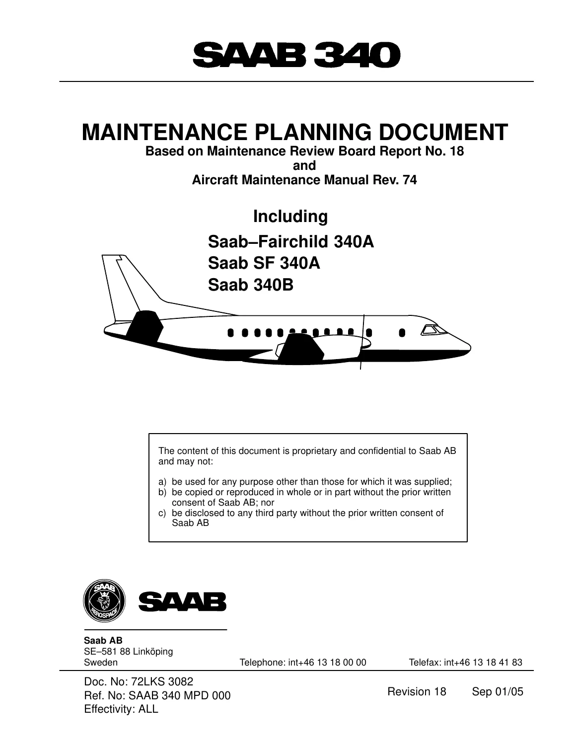
Saab 340A and 340B Maintenance Planning Document 72LKS 3082 Rev 18 2005 PDF — PDF page 1 preview
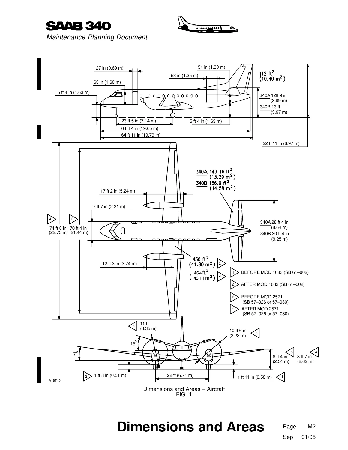
Saab 340A and 340B Maintenance Planning Document 72LKS 3082 Rev 18 2005 PDF — PDF page 540 preview
Saab 340A and 340B Maintenance Planning Document 72LKS 3082 Rev 18 2005 PDF — PDF page 545 preview

Line Check and Routine Inspection Planning

Chapter J provides both line-check requirements and a proposed LC1/LC2 program organized around physical areas of the aircraft. The check sheets address items around the fuselage, empennage, wings, powerplants, propellers and nacelles, and include servicing and visual-condition checks. Examples include inspection for leaks, security and general condition, checking exterior engine and propeller gearbox areas, cowlings, propeller assemblies, de-icing components, fuel vent openings, control surfaces and other externally accessible items.

Aircraft Zones, Access and Dimensions

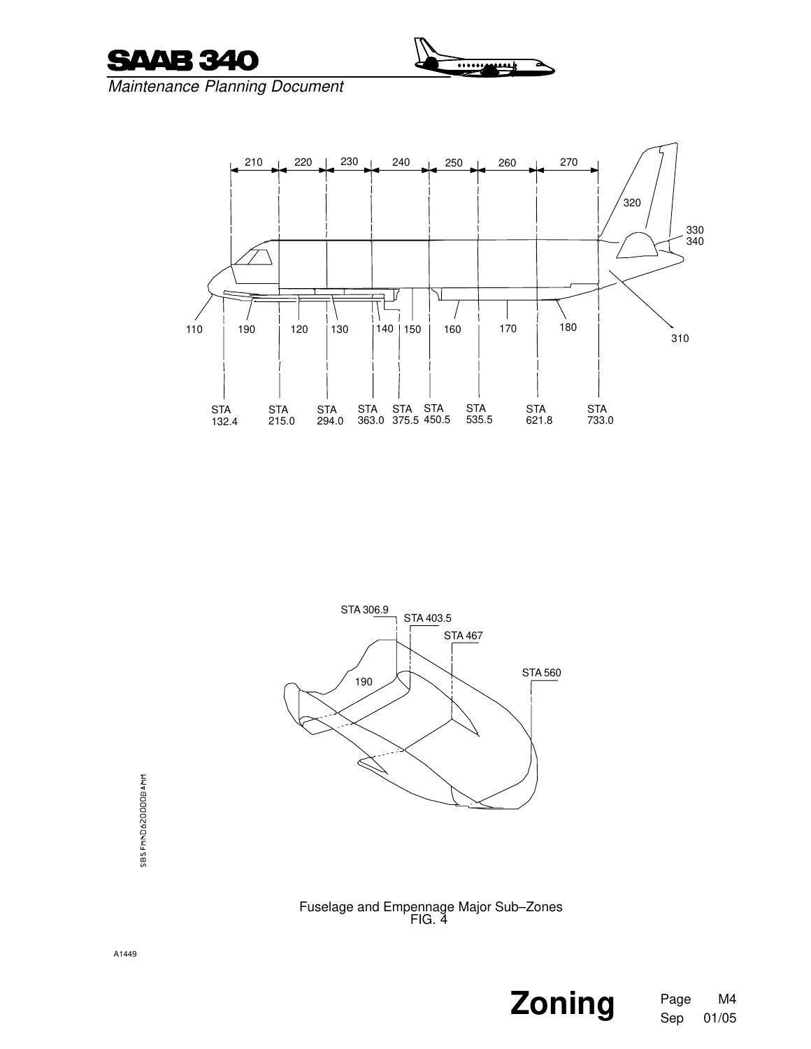
One of the most practical supporting sections is Chapter M, which incorporates dimensions, zoning, stations and access information. It includes illustrated aircraft dimension drawings, major-zone and sub-zone diagrams and access-panel information. These references help maintenance personnel interpret the zone and access designations used throughout the scheduled task tables instead of treating those identifiers as isolated codes.

The dimensions section contains aircraft side, plan and front-view drawings with dimensional and area information. The zoning material visually divides the fuselage, empennage, wings, nacelles and other aircraft areas into the numbered zones used by the MPD, while station references assist in locating structural areas and maintenance access points.

Maintenance Program Development

This document is intended as planning guidance rather than a customized program for a particular airline. Operators use its requirements and intervals as a basis for developing an approved maintenance program appropriate to their fleet and operation. The MPD explains that maintenance-program adjustments are subject to applicable regulatory practices and that the referenced MRB, Aircraft Maintenance Manual or other referenced technical documents take precedence where conflicting information exists.

The equalized-maintenance chapter is useful for operators seeking to distribute workload rather than concentrating large quantities of scheduled work into periodic heavy checks. It discusses operational factors such as fleet size, aircraft utilization, hangars, workshops, docks, platforms, special tools, personnel resources, qualifications and the distribution of maintenance between outstations and the main base.

Plan Saab 340 Scheduled Maintenance with the Correct Task and Interval Reference

The Saab 340A and 340B Maintenance Planning Document 72LKS 3082 Rev 18 2005 PDF gives maintenance planners, engineering departments and technical personnel a structured reference for building and administering Saab 340 scheduled maintenance. It supports identification of system and powerplant tasks, structural inspections, zonal surveillance, line checks, flight-hour and flight-cycle requirements, calendar inspections, rotable tasks, access requirements and maintenance-document cross-references. Having the correct task effectivity, interval, zone, manpower estimate and reference information together is essential when preparing accurate check packages and maintenance schedules.

Delivered as an instant PDF download after purchase. There is no physical book and no shipping delay. The file can be viewed on compatible computers, tablets and phones and pages can be printed when a paper working reference is preferred.

Reviews

There are no reviews yet.

Be the first to review “Saab 340A and 340B Maintenance Planning Document 72LKS 3082 Rev 18 2005 PDF”

What Our Customers Say

★★★★★ Live reviews from customers
Loading customer reviews...
0
    0
    Your Cart
    Your cart is emptyReturn to Shop
    🛒
    Recently Purchased
    🕒 verified order