★ TRUSTED BY 321,897+ PROFESSIONALS WORLDWIDE
🏢
Trusted Business
Verified & Licensed
🛡️
Virus Free Files
100% Safe Downloads
🔒
Secure Payment
SSL Protected
⚡
Instant Delivery
Available Immediately
Sale!

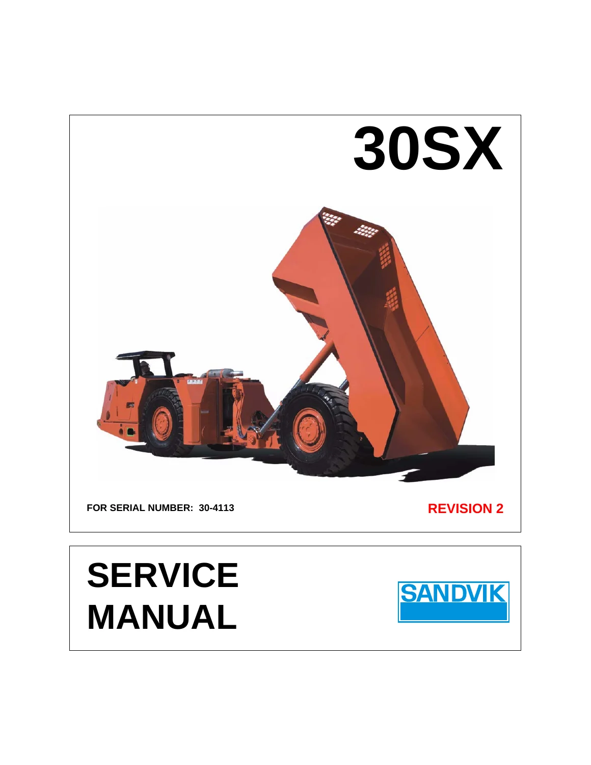
Sandvik EJC 30SX Service Manual – Serial 30-4113 Rev 2 PDF

Original price was: $39.95.Current price is: $24.95.

Complete 249-page Sandvik EJC 30SX Service Manual for serial 30-4113, Revision 2. Covers the Detroit Diesel Series 50 power unit, four-speed powershift drive train, hydraulic circuits, electrical system, frame, hinge, dump box and full preventative maintenance schedule.

⚡
Instant PDF Download
Available immediately
💾
Save to Your Device
Download & keep forever
🛡️
Antivirus Scanned
100% virus-free
🌍
Trusted Worldwide
175,000+ customers

Description

Sandvik EJC 30SX Service Manual – Serial 30-4113, Revision 2

This Sandvik EJC 30SX Service Manual is the complete workshop reference for the 33 ton (30 tonne) underground mining truck, issued for serial number 30-4113 at Revision 2. Across 249 pages it documents the diesel engine and power unit, the four-speed powershift drive train, the hydraulic circuits that steer, dump and brake the machine, the full electrical system, and the frame, hinge and dump box assemblies. Every procedure is written for the person actually holding the wrench: torque values, fluid capacities, pressure settings, inspection intervals, step-by-step removal and installation sequences, and troubleshooting tables that name the probable cause alongside the remedy. If you maintain, repair or rebuild an EJC 30SX, this is the document the factory wrote to go with the machine.

File Details

  • Manual type: Service Manual
  • Brand / publisher: Sandvik Mining and Construction Canada Inc. (EJC Mining Equipment)
  • Model: 30SX
  • Serial number: 30-4113
  • Revision: 2
  • Language: English
  • Page count: 249 pages
  • File format: PDF

Chapters Covered

  • Chapter 1 – Introduction: the Operator’s Manual, how to use this manual, about the 30SX, intended use and restrictions of use, machine orientation and identification plate, machine components and layout, warning/caution/danger/instruction decals, specifications, commissioning and assembly
  • Chapter 2 – Safety: safety precautions when servicing, fire prevention and fire fighting equipment, fire suppression and automatic fire suppression systems, escape procedures for open and closed cab designs, ROPS/FOPS canopy, operator’s compartment door, frame lock installation and storage, back-up alarm, ejector box tailgate, dump box support and lock bars
  • Chapter 3 – Preventative Maintenance: maintenance schedule and procedures, cleaning the axle breather, engine, crankcase breather valve, machine, radiator cooling tubes and fan blades, torque converter and transmission breather, draining the fuel filter/water separator, draining and cleaning the fuel and hydraulic tanks, electrical connections, coolant and oil sampling, greasing drive shafts, battery inspection and cleaning, suction strainer and radiator service, axle, brake, drive shaft, engine belt, fan, mount, thermostat and turbocharger inspection, replacing engine oil and filters, return filter, transmission oil and filter, fluid and lubricant specifications, maintaining a clean hydraulic system and clean diesel fuel supply
  • Chapter 4 – Power Unit: diesel engine removal, maintenance and installation, engine mount torque values, DDEC flash codes, exhaust system, air intake system, engine cooling, charge air cooling, transmission and torque converter oil cooling, radiator cleaning, removal and installation, fuel system, fuel tank removal, inspection and installation, priming the fuel system, fuel filter/water separator element replacement, throttle control
  • Chapter 5 – Drive Train: general description, drive shafts, transmission switches and senders, transmission removal, inspection, maintenance and installation, torque converter operation, lock-up clutch, speed sensor installation and adjustment, axles, brake coolant tank, draining and cleaning the brake coolant tank, front and rear axle removal and installation, axle troubleshooting, tire and wheel rim maintenance, wheel rim assembly and dismounting, tire removal and installation, tire maintenance and storage
  • Chapter 6 – Frame Related: note on welding, centre hinge assembly and disassembly, hinge inspection and maintenance, centre articulation hinge assembly, standard and ejector dump boxes, dump box removal, inspection and installation, lifting points for standard dump box, ejector dump box, extended ejector box, front frame, rear frame, and the engine/torque converter/pump assembly
  • Chapter 7 – Hydraulic System: system description, steering circuit, standard dump box circuit, ejector dump box circuit, brake circuit, brake cooling circuit, hydraulic tank assembly, hydraulic pumps, filters, accumulator charge valve, accumulators, accumulator/valving assembly, auto and manual bleed down valves, manual hand pump, ejector dump box sequence valve calibration, pressure testing and test port locations, comprehensive troubleshooting
  • Chapter 8 – Electrical System: electrical drawings and schematics, circuit protection, electrical connections, wire identification, common electrical symbols, electrical component locations, charging circuit, power circuit, start circuit, automatic lube circuit, ECM circuit, monitor circuit, brake circuit, tow circuit, front and rear lights circuits, transmission circuit, lock-up circuit, cab wiring circuit, reversing camera circuit, electrical troubleshooting
  • Chapter 9 – Towing the Machine: preparation and towing, applying the brakes in an emergency, operating the manual hand pump
  • Appendix A – Reference Material
  • Appendix B – Drawings and Schematics
  • Appendix C – Material Safety Data Sheets
  • Appendix D – Torque Values for Standard Hardware

Taken as a whole, the manual walks a technician through the machine from the ground up. It opens with the specifications and fluid capacities you need before a single panel comes off, then moves into the scheduled preventative maintenance routines that keep an underground truck alive in dust and heat. From there it descends into the major assemblies one at a time: pulling and reinstalling the Series 50 diesel and its torque converter, opening the transmission, servicing the Kessler axles and wheel ends, replacing the centre articulation hinge pins, and working the dump box pivots and lifting points. The hydraulic chapter explains each circuit in words as well as schematic symbols, so you can follow oil from the pump through the amplifier valve, accumulator charge valve and relay valves, and the electrical chapter does the same for every circuit from the charging system to the reversing camera. Troubleshooting tables at the end of the hydraulic and electrical chapters turn a symptom into a short list of probable causes and remedies, which is often the fastest route to a fix on a machine that cannot afford to sit.

Who This Manual Suits

Underground mine maintenance crews, heavy equipment mechanics, rebuild shops, and fleet owners running EJC 30SX trucks will all find something here. Because the coverage is written around a specific serial number and revision, the torque values, pressures and adjustment figures match the machine rather than a generic range. Component-level procedures are supported by manufacturer reference literature listed in Appendix A, so when a job needs the Clark transmission manual or the Kessler axle manual, the manual points you to it. Appendix D closes the loop with standard metric, UNC and UNF torque values for the hardware you are actually turning.

What You Can Do With It

  • Run the full preventative maintenance schedule by hour interval, from the first 50-hour service through the 10,000-hour fuel tank service and the five-year fire suppression squib replacement.
  • Remove and reinstall the engine, torque converter, transmission, radiators, axles and hydraulic tank with the correct lift points, torque values and fluid capacities.
  • Diagnose hydraulic faults such as low steer pressure, slow dump box action, frequent accumulator charge cycles and brakes that will not release.
  • Trace electrical faults across the charging, power, start, monitor, brake, light, transmission and lock-up circuits.
  • Service tires and multi-piece wheel rims safely, including demounting, mounting and the correct wheel nut torque sequence.
  • Calibrate the ejector dump box sequence valve and the torque converter lock-up speed sensor.

Why The Correct Procedures Matter

An underground haul truck works in conditions that punish shortcuts. Contaminated hydraulic oil takes out pumps and valves, an over-torqued wheel nut cracks a rim, an unsupported dump box drops on the person under it, and a mis-set accumulator leaves the brakes unable to release. This manual spells out the safe sequence and the correct figure for each of those jobs, along with the warnings, cautions and lock-out steps that go with them. Having the right numbers in front of you is the difference between a repair that lasts and one that comes back.

Complete PDF Bookmark Tree

Complete Bookmarks

The complete bookmarks in the “Sandvik EJC 30SX Service Manual – Serial 30-4113 Rev 2 PDF” are as follows:

Service Manualp. 1
Prefacep. 3
Table of Contentsp. 5
Introductionp. 13
1.1 The Operator’s Manualp. 14
1.2 How To Use This Manualp. 14
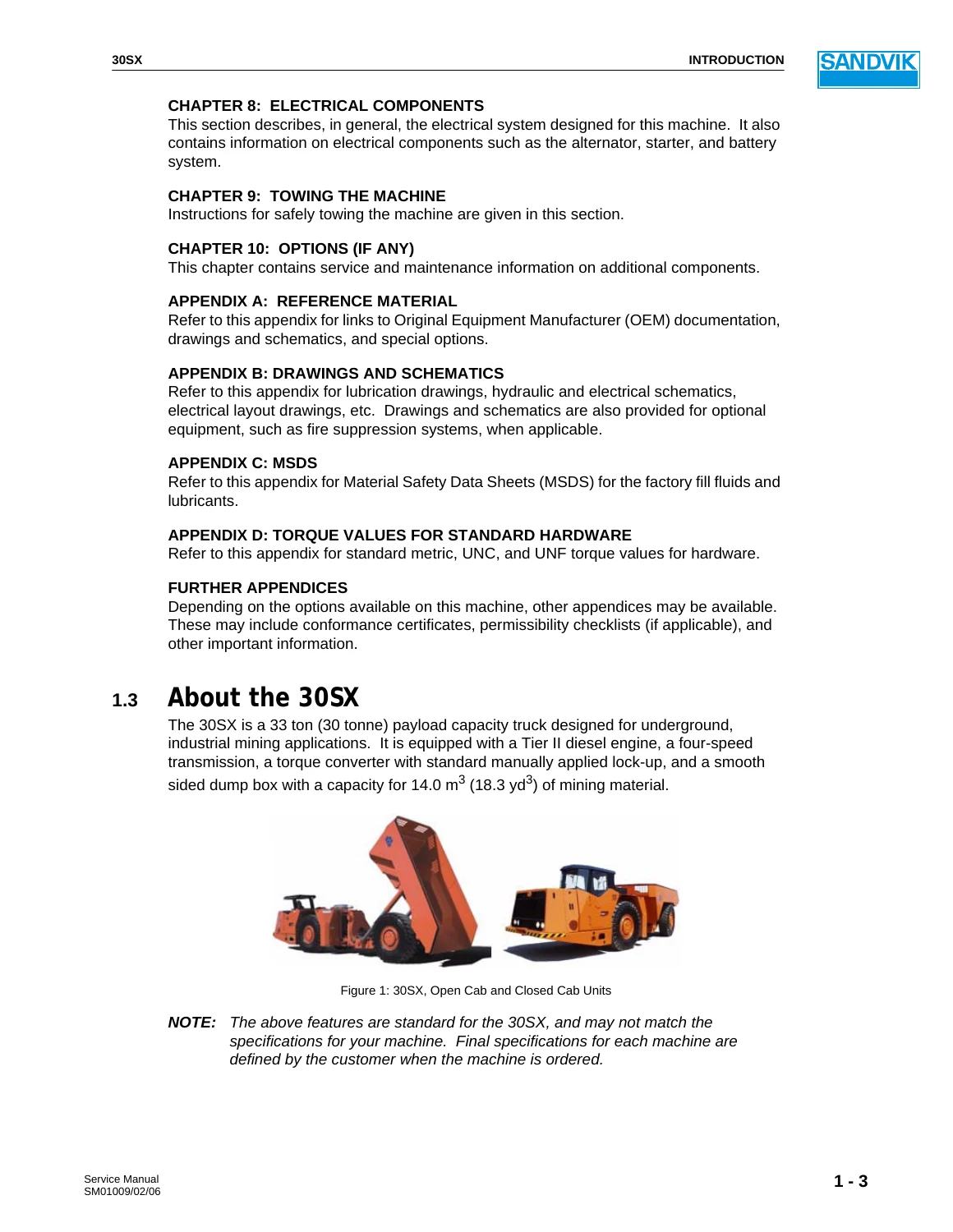
1.3 About the 30SXp. 15
1.4 Intended Use of the Machinep. 16
1.5 Restrictions Of Usep. 16
1.6 Orientationp. 16
1.6.1 Machine Identificationp. 16
1.6.2 Machine Componentsp. 17
1.6.3 Machine Layoutp. 18
1.7 Decalsp. 18
1.7.1 Warning Decalsp. 18
1.7.2 Caution Decalsp. 19
1.7.3 Danger Decalsp. 19
1.7.4 Instructionsp. 20
1.7.5 General Informationp. 20
1.8 Specificationsp. 21
1.8.1 Maximum Carrying Capacityp. 21
1.8.2 Maximum Speedp. 21
1.8.3 Vehicle Weightp. 21
1.8.4 Hydraulic Systemp. 22
1.8.5 Fluid Capacitiesp. 22
1.8.6 Overall Dimensionsp. 23
1.9 Commissioning and Assemblyp. 25
Safetyp. 27
2.1 Safety Precautions When Servicingp. 28
2.2 Fire Prevention, Equipment, and Proceduresp. 29
2.2.1 Fire Preventionp. 29
2.2.2 If a Fire Occurs On the Machinep. 30
2.2.3 Hand-Held Fire Extinguisherp. 31
2.2.4 Fire Suppression System (If Equipped)p. 32
2.2.5 Automatic Fire Suppression System (If Equipped)p. 33
2.2.6 Servicing the Fire Suppression Systemp. 34
2.3 Escape Proceduresp. 34
2.3.1 Escape Paths for Open Cab Designsp. 34
2.3.2 Escape Paths for Closed Cab Designsp. 34
2.4 ROPS/FOPS Canopyp. 35
2.5 Operator’s Compartment Doorp. 36
2.6 Frame Lockp. 36
2.6.1 Installing the Frame Lockp. 36
2.6.2 Storing the Frame Lockp. 37
2.7 Back-Up Alarmp. 38
2.8 Ejector Box Tailgate (If Equipped)p. 38
2.9 Dump Box Support/Lock Barsp. 38
Preventative Maintenancep. 39
3.1 Preventative Maintenance Schedule and Proceduresp. 40
3.1.1 Cleaning the Axle Breatherp. 43
3.1.2 Cleaning the Enginep. 43
3.1.3 Cleaning the Engine Crankcase Breather Valvep. 44
3.1.4 Cleaning the Machinep. 44
3.1.5 Cleaning the Radiator Cooling Tubes and Fan Bladesp. 45
3.1.6 Cleaning the Torque Converter and Transmission Breatherp. 45
3.1.7 Draining the Fuel Filter/Water Separatorp. 46
3.1.8 Draining and Cleaning the Fuel Tankp. 47
3.1.9 Draining and Cleaning the Hydraulic Tankp. 49
3.1.10 Electrical Connectionsp. 51
3.1.11 Engine Coolant Samples (Level 1)p. 52
3.1.12 Engine Coolant Samples (Level 2)p. 52
3.1.13 Engine Oil Samplesp. 53
3.1.14 Greasing the Drive Shaftsp. 53
3.1.15 Hydraulic Oil Samplesp. 54
3.1.16 Inspecting and Cleaning the Batteriesp. 54
3.1.17 Inspecting and Cleaning the Hydraulic Tank Suction Strainerp. 56
3.1.18 Inspecting and Cleaning the Radiatorp. 58
3.1.19 Inspecting Engine Hoses and Connectionsp. 61
3.1.20 Inspecting Tires and Wheel Rimsp. 61
3.1.21 Inspecting the Accumulator Pre-Charge Pressurep. 62
3.1.22 Inspecting the Air Intake and Exhaust Mounting Boltsp. 62
3.1.23 Inspecting the Alternator and Starterp. 63
3.1.24 Inspecting the Axle Hardwarep. 63
3.1.25 Inspecting the Axle Oil Level and Sealsp. 63
3.1.26 Inspecting the Axle Mountsp. 64
3.1.27 Inspecting the Automatic Fire Suppression System (If Equipped)p. 65
3.1.28 Inspecting the Brake Systemp. 67
3.1.29 Inspecting the Drive Shaftsp. 67
3.1.30 Inspecting the Electrical Enclosuresp. 68
3.1.31 Inspecting the Engine Beltsp. 68
3.1.32 Inspecting the Engine Fanp. 72
3.1.33 Inspecting the Engine Mountsp. 72
3.1.34 Inspecting the Engine Thermostatsp. 73
3.1.35 Inspecting the Fire Suppression System (If Equipped)p. 75
3.1.36 Inspecting the Hydraulic Tank Breather Valvep. 76
3.1.37 Inspecting the Hydraulic Systemp. 77
3.1.38 Inspecting the Transmission Mountsp. 78
3.1.39 Inspecting the Turbochargerp. 78
3.1.40 Inspecting the Wheel Rimsp. 79
3.1.41 Measuring Restrictions in the Exhaust Systemp. 80
3.1.42 Servicing the Dry Type Air Cleanerp. 81
3.1.43 Replacing the Axle Differential Oilp. 82
3.1.44 Replacing the Battery in the Checkfire SC-N Control Module (If Equipped)p. 84
3.1.45 Replacing the Engine Beltsp. 85
3.1.46 Replacing the Engine Coolant Additive Filter Elementp. 85
3.1.47 Replacing the Engine Oil and Filter Elementsp. 87
3.1.48 Replacing the Engine Thermostatsp. 88
3.1.49 Replacing the Fire Suppression System Squib (If Equipped)p. 90
3.1.50 Replacing the Return Filter Elementp. 91
3.1.51 Replacing the Torque Converter/Transmission Oil, and Filterp. 92
3.1.52 Walk-Around Inspectionp. 95
3.2 Fluid and Lubricant Specificationsp. 95
3.2.1 Industry Specificationsp. 95
3.2.2 Typical Factory Fillp. 96
3.2.3 Diesel Fuelp. 96
3.2.4 Engine Oilp. 97
3.2.5 Hydraulic Oilp. 97
3.2.6 Coolantp. 98
3.2.7 Torque Converter and Transmission Oilp. 99
3.2.8 Axle and Brake Oilp. 99
3.2.9 Multi-Purpose Greasep. 100
3.2.10 Fire Resistant Fluids (FRF)p. 100
3.2.11 Disposal Considerationsp. 100
3.3 Maintaining a Clean Hydraulic Systemp. 100
3.3.1 Prevent Contaminants From Entering the Systemp. 100
3.3.2 Oil Storage and Handlingp. 101
3.3.3 Replenishing or Changing the Hydraulic Oil Supplyp. 101
3.4 Maintaining a Clean Diesel Fuel Supplyp. 101
Power Unitp. 103
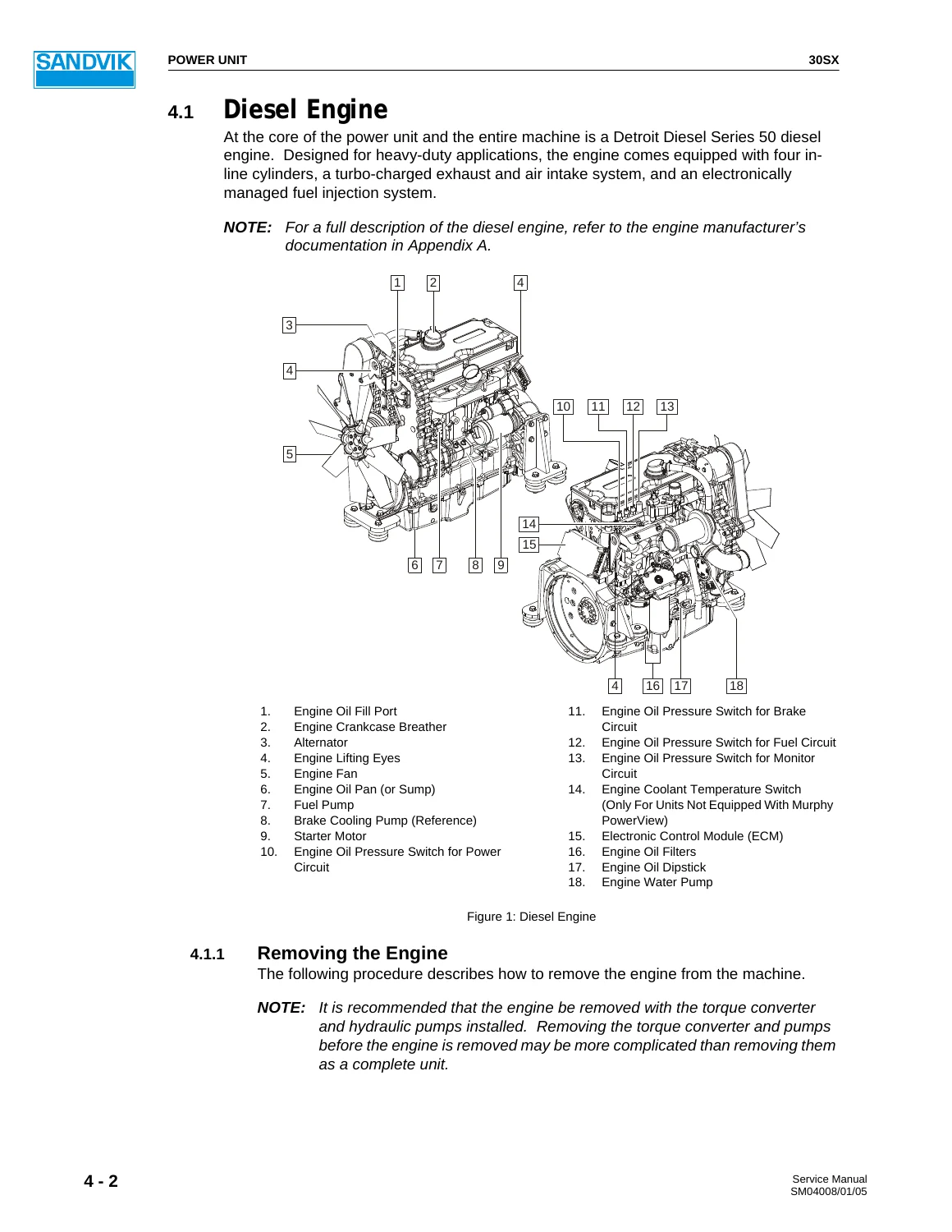
4.1 Diesel Enginep. 104
4.1.1 Removing the Enginep. 104
4.1.2 Maintenancep. 106
4.1.3 Installing the Enginep. 106
4.1.4 Engine Mount Torque Valuesp. 109
4.1.5 DDEC Flash Codesp. 110
4.2 Exhaust Systemp. 112
4.3 Air Intake Systemp. 113
4.4 Cooling Systemp. 114
4.4.1 Engine Coolingp. 114
4.4.2 Charge Air Coolingp. 115
4.4.3 Transmission and Torque Converter Oil Coolingp. 115
4.4.4 Cleaning and Maintaining the Radiatorp. 116
4.4.5 Removing the Radiatorp. 116
4.4.6 Installing the Radiatorp. 117
4.5 Fuel Systemp. 118
4.5.1 Removing the Fuel Tankp. 119
4.5.2 Inspection and Maintenancep. 120
4.5.3 Installing the Fuel Tankp. 121
4.5.4 Priming the Fuel Systemp. 121
4.5.5 Replacing the Fuel Filter/Water Separator Elementp. 122
4.6 Throttle Controlp. 123
Drive Trainp. 125
5.1 General Descriptionp. 126
5.2 Drive Shaftsp. 126
5.3 Transmissionp. 127
5.3.1 Switches and Sendersp. 127
5.3.2 Removing the Transmissionp. 128
5.3.3 Inspection and Maintenancep. 129
5.3.4 Installing the Transmissionp. 129
5.4 Torque Converterp. 130
5.4.1 Torque Converter Operationp. 131
5.4.2 Torque Converter Lock-Up Clutch (If Equipped)p. 132
5.4.3 Speed Sensor Installationp. 133
5.4.4 Adjusting the Speed Sensorp. 134
5.5 Axlesp. 135
5.5.1 Brake Coolant Tankp. 135
5.5.2 Draining and Cleaning the Brake Coolant Tankp. 135
5.5.3 Removing the Front Axlep. 137
5.5.4 Removing the Rear Axlep. 138
5.5.5 Inspection and Maintenancep. 139
5.5.6 Installing the Front Axlep. 140
5.5.7 Installing the Rear Axlep. 140
5.5.8 Troubleshootingp. 140
5.6 Tire and Wheel Rim Maintenancep. 141
5.6.1 Working With Inflated Tires and Multi-Piece Wheel Rimsp. 141
5.6.2 Safe Service Proceduresp. 142
5.6.3 Recommended Toolsp. 143
5.6.4 Tire Handling Recommendationsp. 143
5.6.5 Wheel Rim Assemblyp. 144
5.6.6 Demounting the Wheel Rim Assemblyp. 144
5.6.7 Mounting the Wheel Rim Assemblyp. 145
5.6.8 Removing Tires from Wheel Rim Assembliesp. 147
5.6.9 Installing Tires to Wheel Rim Assembliesp. 147
5.6.10 Tire Maintenance and Storagep. 148
5.6.11 Wheel Rim Maintenance and Storagep. 150
Frame Relatedp. 151
6.1 Note On Weldingp. 152
6.2 Centre Hinge Assembly and Disassemblyp. 152
6.2.1 Hinge Assemblyp. 153
6.2.2 Disassembling the Centre Articulation Hingep. 153
6.2.3 Inspection and Maintenancep. 155
6.2.4 Assembling the Centre Articulation Hingep. 155
6.3 Standard and Ejector Dump Boxes (If Equipped)p. 156
6.3.1 Removing the Standard Dump Box (If Equipped)p. 156
6.3.2 Removing the Ejector Dump Box (If Equipped)p. 157
6.3.3 Inspection and Maintenancep. 158
6.3.4 Installing the Standard Dump Box (If Equipped)p. 159
6.3.5 Installing the Ejector Dump Box (If Equipped)p. 159
6.4 Lifting Pointsp. 159
6.4.1 Standard Dump Box Lifting Points (If Equipped)p. 160
6.4.2 Ejector Dump Box Lifting Points (If Equipped)p. 160
6.4.3 Extended Ejector Box Lifting Points (If Equipped)p. 161
6.4.4 Front Frame Lifting Pointsp. 161
6.4.5 Rear Frame Lifting Pointsp. 161
6.4.6 Engine, Torque Converter, and Pumps Assemblyp. 163
Hydraulic Systemp. 165
7.1 System Descriptionp. 166
7.1.1 Steering Circuitp. 166
7.1.2 Standard Dump Box Circuit (If Equipped)p. 167
7.1.3 Ejector Dump Box Circuit (If Equipped)p. 168
7.1.4 Brake Circuitp. 170
7.1.5 Brake Cooling Circuitp. 174
7.2 Hydraulic Tank Assemblyp. 174
7.2.1 Removing the Hydraulic Tankp. 175
7.2.2 Inspection and Maintenancep. 176
7.2.3 Installing the Hydraulic Tankp. 177
7.3 Hydraulic Pumpsp. 177
7.3.1 Removing the Dump Box, Steer, Brake Charge, and Scavenge Pumpsp. 178
7.3.2 Removing the Brake Cooling Pumpp. 179
7.3.3 Inspections and Maintenancep. 179
7.3.4 Installing the Dump Box, Steer, Brake Charge, and Scavenge Pumpsp. 179
7.3.5 Install the Brake Cooling Pumpp. 180
7.4 Filtersp. 180
7.5 Accumulator Charge Valvep. 181
7.6 Accumulatorsp. 182
7.6.1 Functional Descriptionp. 183
7.7 Accumulator/Valving Assemblyp. 184
7.7.1 Brake Accumulator Pressurep. 184
7.7.2 Park/Emergency Brake Light/Buttonp. 184
7.8 Auto and Manual Bleed Down Valvesp. 185
7.9 Manual Hand Pumpp. 185
7.10 Ejector Dump Box Sequence Valve (If Equipped)p. 186
7.10.1 Calibrating the Ejector Dump Box Sequence Valvep. 186
7.11 Pressure Testingp. 188
7.11.1 Conducting Pressure Testsp. 188
7.11.2 Test Port Locationsp. 188
7.12 Troubleshootingp. 190
7.12.1 Pump Not Delivering Oilp. 190
7.12.2 Excessive Pump Noisep. 190
7.12.3 System Excessively Hotp. 191
7.12.4 No Pressurep. 191
7.12.5 Fluctuating System Pressurep. 192
7.12.6 Insufficient System Pressurep. 192
7.12.7 No Hydraulic Actionp. 193
7.12.8 Leakage At Pump Oil Sealp. 193
7.12.9 No Motion of Dump Box Cylinderp. 193
7.12.10 Slow or Uneven Action of the Dump Box Cylinder(s)p. 194
7.12.11 Spongy or Jerky Action of the Dump Box Cylinderp. 194
7.12.12 Excessive Cylinder Creep Ratep. 194
7.12.13 No Steering or Emergency Steer Circuit Activep. 194
7.12.14 Poor Controlp. 194
7.12.15 Steer Pressure Lowp. 195
7.12.16 Orbitrol Valve Has External Leakagep. 195
7.12.17 Brake Fault Light Does Not Illuminate When Accumulator Gauge Shows Less Than 1600 PSI (110 Bar)p. 195
7.12.18 Brakes Will Not Releasep. 195
7.12.19 Charge Cycle Repeats Frequently When Brake Functions Are Not Usedp. 195
7.12.20 Accumulator Charging Time Too Longp. 196
7.12.21 Brake Pressure Lowp. 196
Electrical Systemp. 197
8.1 Electrical Drawings and Schematicsp. 198
8.2 Circuit Protectionp. 198
8.3 Electrical Connectionsp. 198
8.4 Wire Identificationp. 199
8.5 Common Electrical Symbolsp. 199
8.6 Electrical Component Locationsp. 203
8.6.1 Enginep. 204
8.6.2 Transmissionp. 205
8.6.3 Torque Converterp. 206
8.7 Charging Circuitp. 206
8.7.1 Circuit Protectionp. 206
8.7.2 Circuit Logicp. 206
8.8 Power Circuitp. 207
8.8.1 Circuit Protectionp. 207
8.8.2 Circuit Logicp. 207
8.9 Start Circuitp. 207
8.9.1 Circuit Protectionp. 207
8.9.2 Circuit Logicp. 207
8.10 Automatic Lube Circuit (If Equipped)p. 209
8.10.1 Circuit Protectionp. 209
8.10.2 Circuit Logicp. 209
8.11 ECM Circuitp. 210
8.11.1 Circuit Protectionp. 210
8.11.2 Circuit Logicp. 210
8.12 Monitor Circuitp. 210
8.12.1 Circuit Protectionp. 210
8.12.2 Circuit Logicp. 211
8.13 Brake Circuitp. 215
8.13.1 Circuit Protectionp. 215
8.13.2 Circuit Logicp. 215
8.13.3 Automatic Brake Applicationp. 216
8.13.4 Tow Circuitp. 217
8.14 Front Lights Circuitp. 217
8.14.1 Circuit Protectionp. 217
8.14.2 Circuit Logicp. 217
8.15 Rear Lights Circuitp. 218
8.15.1 Circuit Protectionp. 218
8.15.2 Circuit Logicp. 218
8.16 Transmission Circuitp. 220
8.16.1 Circuit Protectionp. 220
8.16.2 Circuit Logicp. 220
8.16.3 Gear Shiftingp. 221
8.17 Lock-Up Circuitp. 222
8.17.1 Circuit Protectionp. 222
8.17.2 Circuit Logicp. 222
8.18 Cab Wiring Circuit (If Equipped)p. 223
8.18.1 Circuit Protectionp. 223
8.18.2 Dome Light Circuitp. 223
8.18.3 Wiper Circuitp. 224
8.18.4 Temperature and Condenser Circuitsp. 224
8.19 Reversing Camera Circuit (If Equipped)p. 225
8.19.1 Circuit Protectionp. 225
8.19.2 Circuit Logicp. 225
8.20 Troubleshootingp. 226
8.20.1 Engine Does Not Turn Overp. 226
8.20.2 Engine Starts, Then Immediately Stopsp. 227
8.20.3 Engine Turns Over But Does Not Startp. 227
8.20.4 Engine Stalls During Normal Operationp. 227
8.20.5 Brakes Remain Appliedp. 228
8.20.6 Indicator Lights Do Not Workp. 229
8.20.7 Hourmeter Does Not Work When Engine Runningp. 230
8.20.8 Voltmeter Gauge or Light Does Not Workp. 230
8.20.9 Front/Rear Lights Do Not Workp. 230
8.20.10 Front/Rear Lights Dim, Engine Runningp. 231
8.20.11 Back-Up Alarm Does Not Work When Shifter In Reversep. 231
8.20.12 Horn Does Not Workp. 231
Towing the Machinep. 233
9.1 Preparation and Towingp. 234
9.2 Applying the Brakes in an Emergencyp. 235
9.3 Operating the Manual Hand Pumpp. 236
Reference Materialp. 237
Drawings and Schematicsp. 241
Material Safety Data Sheetsp. 243
Torque Values for Standard Hardwarep. 245


IMAGES PREVIEW

Sandvik EJC 30SX Service Manual - Serial 30-4113 Rev 2 PDF — PDF page 1 preview
Sandvik EJC 30SX Service Manual - Serial 30-4113 Rev 2 PDF — PDF page 15 preview
Sandvik EJC 30SX Service Manual - Serial 30-4113 Rev 2 PDF — PDF page 104 preview

Instant PDF Delivery

The Sandvik EJC 30SX Service Manual is delivered as a PDF download immediately after checkout, with no shipping and no waiting. Read it on a laptop in the shop, a tablet at the machine, or a phone in the drift, and print any page or diagram you want to take with you. Keep a copy on the service truck and another in the office so the whole crew has the same reference. Add it to your library today and put the factory procedures for serial 30-4113 in the hands of whoever is doing the work.

Reviews

There are no reviews yet.

Be the first to review “Sandvik EJC 30SX Service Manual – Serial 30-4113 Rev 2 PDF”

What Our Customers Say

★★★★★ Live reviews from customers
Loading customer reviews...
0
    0
    Your Cart
    Your cart is emptyReturn to Shop
    🛒
    Recently Purchased
    🕒 verified order