★ TRUSTED BY 321,897+ PROFESSIONALS WORLDWIDE
🏢
Trusted Business
Verified & Licensed
🛡️
Virus Free Files
100% Safe Downloads
🔒
Secure Payment
SSL Protected
⚡
Instant Delivery
Available Immediately
Sale!

FLSmidth 1300 x 1800 TSU Gyratory Crusher Installation, Operation and Maintenance Manual

Original price was: $44.95.Current price is: $27.95.

Complete 366-page FLSmidth IOM manual for the 1300 x 1800 Top Service Ultra Duty gyratory crusher, covering installation, commissioning, operation, maintenance, troubleshooting, lubrication, hydraulics and parts. Instant PDF download.

⚡
Instant PDF Download
Available immediately
💾
Save to Your Device
Download & keep forever
🛡️
Antivirus Scanned
100% virus-free
🌍
Trusted Worldwide
175,000+ customers

Description

FLSmidth 1300 x 1800 TSU Gyratory Crusher – Complete Installation, Operation and Maintenance Manual

This FLSmidth 1300 x 1800 Top Service Ultra Duty (TSU) Gyratory Crusher Installation, Operation and Maintenance Manual is the full IOM documentation package issued for the Ravenswood Gold Mine project under document number 9232510974, dated September 2021. It covers every phase of the crusher’s service life – from foundation preparation and component assembly, through commissioning, ore crushing operations, scheduled preventive maintenance, major component replacement, and field troubleshooting. Written by FLSmidth engineers for the 1300 x 1800 TSU specifically, it is the primary field reference for the crusher, its lubrication system, hydraulic adjustment system, spider lubrication system, drive arrangement and control interlocks.

File Details

  • Manual type: Installation, Operation, and Maintenance Manual (IOM)
  • Equipment: FLSmidth Gyratory Crusher 1300 x 1800 Top Service Ultra Duty (TSU)
  • Document number: 9232510974 / 10007027431
  • Project: Ravenswood Gold Mine
  • Revision date: September 2021
  • Language: English
  • Page count: 366 pages
  • File format: PDF
  • Drive motor rating: 450 kW
  • Feed opening: 1300 mm (51 in)
  • Maximum mantle diameter: 1800 mm (71 in)

Chapters Covered

  • Chapter 1 – Safety: hazard signal indicators, mandatory action and prohibition symbols, warning symbols, safe working practices, operator responsibilities, unauthorized modifications, lockout/tagout energy isolation, fire extinguishers, emergency procedures, equipment safety signs and labels, protective devices (emergency stop switches, safety trip wire, interlocks, guards), equipment-specific risks, slip/trip/fall hazards, pressurized hydraulics and lubrication, lifting and moving heavy components, flying or falling objects, confined spaces, respiratory concerns, high noise levels, crusher control system interlocks, tool safety, general risks and hazards, hazardous chemicals and materials
  • Chapter 2 – Introduction: using the manual, installation and start-up services, shipment and receiving, parts and repair orders, warranty conditions, accessory equipment manufacturer information, FLSmidth offices
  • Chapter 3 – Storage: long-term storage, maintaining warranty, storing OEM components, outdoor storage, covered or indoor storage, equipment support, preventing corrosion (shop primer paints, protective finishes, machined surfaces), storing elastomer components, storing fiberglass reinforced plastic components, storing equipment after operation, storing methods, environmental precautions
  • Chapter 4 – Equipment Overview: crusher body, spider assembly, concaves and mantles, eccentric, mainshaft wear ring
  • Chapter 5 – Installation: installation considerations, bolt torque values, interference fit components (heating and cooling methods), receipt of material, foundation preparation, hydraulic support and cylinder installation, bottom shell installation and grouting, bottom shell liners, eccentric installation, countershaft assembly, dust bonnet and gear guard, shells installation, concave installation, spider and mainshaft installation, lip seals, top shell wear and seal plates, mantle position indicator, lubrication and hydraulic installation, drive motor and couplings, torque limiting coupler, drive guard, countershaft low speed switch, dust seal blower, rock breaker, post-installation inspection, final mechanical inspection and commissioning
  • Chapter 6 – Operation: start-up from complete shutdown, standby shutdown, emergency shutdown and power failure, shutdown operations, ore receiving and crushing inspections, adjusting the crusher open-side setting, clearing the crusher, clearing tramp material jam, rock breaker use
  • Chapter 7 – Maintenance: component replacement, running and shutdown mechanical inspections, major mechanical preventive maintenance, electrical and instrument preventive maintenance, manganese steel growth and trimming of concaves and mantles, stator insulation resistance measurement, dust bonnet replacement, spider replacement, mainshaft replacement, mantle replacement, core replacement, eccentric replacement, hydraulic piston replacement, hydraulic cylinder replacement, countershaft assembly maintenance, concaves replacement, extension shaft maintenance
  • Chapter 8 – Troubleshooting: general crusher troubleshooting, mainshaft and eccentric assembly troubleshooting, lubrication system troubleshooting, drive system troubleshooting, concave troubleshooting, liner troubleshooting, troubleshooting process variables
  • Appendix A – Lubrication: lubrication schedule, oil and grease selection, crusher hydraulic and lubrication systems, spider lubrication system, mainshaft dust seal and countershaft triple seal, drive safety coupling bearings, oil and grease quantity, oil contamination, oil viscosity, oil sampling
  • Appendix B – Pre-Installation Inspection: component-by-component inspection form
  • Appendix C – Commissioning: commissioning overview, sequence flow chart, pre-operational testing, pre-commissioning mechanical and electrical inspection, instrumentation, no-load commissioning, 50% feed load commissioning, full load commissioning
  • Appendix D – Maintenance Schedule: daily, weekly, monthly, annual and major mechanical checklists; weekly, monthly and annual electrical checklists; quarterly instrument checklist
  • Appendix E – Parts List / Bill of Materials: assembly-by-assembly parts lists with part numbers, drawings, materials and weights
  • Appendix F – Recommended Spare Parts List: start-up and commissioning spares, second-year operational spares, capital and insurance spares
  • Appendix G – Functional Specification (Document 1000656041): lubrication system interlocks and controls, spider lubrication system, hydraulic system, mantle solenoids, mantle position calibration, dust seal fan, countershaft speed, main drive interlocks, crusher feed permission
  • Appendix H – Drawing Package: crusher general assembly, foundation load and clearance requirements, foundation bolt assembly, mainshaft/spider/shell handling drawings, spider assembly, top shell assembly, top shell seal assembly, middle shell assembly, bottom shell assembly, bottom shell liner assembly, dust bonnet assembly, eccentric assembly, hydraulic cylinder assembly, mainshaft assembly, concave assembly, concave installation and removal rings, bonnet cover, countershaft assembly, lube and hydraulic schematic, spider lubrication GA, countershaft extension assembly, drive guard assembly, dust seal assembly, mantle position indicator assembly, hydraulic jack assembly, mantle relief valve and accumulator, blower assembly schematic, gear and pinion assembly field installation, erection and maintenance data, acceptable epoxy grouts, instrument list, electrical load list, control and instrumentation diagram, interconnection drawing, lubrication unit electrical schematic, block diagram, I/O list
  • Appendix I – Final Mechanical Inspection: field sign-off checklist

Complete PDF Bookmark Tree

Complete Bookmarks

The complete bookmarks in the “FLSmidth 1300 x 1800 TSU Gyratory Crusher Installation, Operation and Maintenance Manual” are as follows:

Cover Pagep. 1
Table of Contentsp. 3
Chapter 1: Safetyp. 13
1.1 Important Safety Informationp. 15
1.1.1 Hazard Signal Indicatorsp. 15
1.1.2 Safety Signs and Symbolsp. 15
1.1.2.1 Mandatory Action Symbolsp. 16
1.1.2.2 Prohibition Symbolsp. 16
1.1.2.3 Warning Symbolsp. 18
1.2 Safe Working Practicesp. 19
1.2.1 Operator Responsibilitiesp. 19
1.2.2 General Safety Recommendationsp. 19
1.2.3 Unauthorized Modificationsp. 20
1.2.4 Lockout/Tagout (Energy Isolation)p. 20
1.2.5 Fire Extinguishersp. 20
1.2.6 Emergency Proceduresp. 20
1.2.7 Equipment Safety Signs and Labelsp. 21
1.2.8 Protective Devicesp. 21
1.2.8.1 Emergency Stop Switchesp. 21
1.2.8.2 Safety Trip Wirep. 21
1.2.8.3 Interlocksp. 22
1.2.8.4 Guardsp. 22
1.3 Equipment-Specific Risks and Hazardsp. 23
1.3.1 Moving Components and Pinch Pointsp. 23
1.3.1.1 Area Above the Crusherp. 23
1.3.1.2 Power Transmissionp. 23
1.3.1.3 Hydraulic Adjustment Assemblyp. 23
1.3.2 Slip, Trip, and Fall Hazardsp. 24
1.3.3 Pressurized Hydraulics and Lubricationp. 24
1.3.4 Lifting and Moving Heavy Componentsp. 24
1.3.5 Flying or Falling Objectsp. 25
1.3.6 Confined Spacesp. 25
1.3.7 Respiratory Concernsp. 25
1.3.8 High Noise Levelsp. 26
1.3.9 Crusher Control System Operating and Safety Interlocksp. 26
1.3.10 Toolsp. 26
1.4 General Risks and Hazardsp. 27
1.4.1 Identifying and Controlling Hazardsp. 27
1.4.2 Laddersp. 28
1.4.3 Scaffoldsp. 28
1.4.4 Railingsp. 28
1.4.5 Elevated Work Conditionsp. 28
1.4.6 Harness and Line (Fall-Arrest System)p. 28
1.4.7 Cranes and Lifting Operationsp. 28
1.4.8 Moving Parts on Stationary Equipmentp. 29
1.4.9 Remote Startsp. 29
1.4.10 Confined Spacesp. 29
1.4.11 Welding, Cutting, and Brazingp. 29
1.4.12 High Temperaturesp. 29
1.4.13 Power Linesp. 30
1.4.14 Inclement Weatherp. 30
1.4.15 Noise and Vibrationsp. 30
1.4.16 Pinch and Crush Pointsp. 30
1.4.17 Electrical Energyp. 31
1.4.18 Fuels, Oils, and Lubricating Fluidsp. 31
1.4.19 Surface Heatp. 32
1.4.20 Lines, Tubes, and Hosesp. 32
1.4.21 Mechanical Stabilityp. 33
1.5 Hazardous Chemicals and Materialsp. 33
1.5.1 Mineral Powders (Silica)p. 33
1.5.2 Lime and Calcined Raw Mealp. 33
1.5.3 Cementp. 33
1.5.4 Acids and Basesp. 34
1.5.5 Cyanidep. 34
1.5.6 Solventsp. 34
1.6 Emergency Preparedness Planp. 34
Chapter 2: Introductionp. 35
2.1 Using this Manualp. 36
2.2 Installation and Start-up Servicesp. 36
2.3 Shipment and Receivingp. 37
2.4 Parts and Repair Ordersp. 37
2.5 Warranty Conditionsp. 37
2.5.1 Limited Warrantyp. 38
2.6 Accessory Equipment Manufacturer Informationp. 38
2.7 FLSmidth Officesp. 39
Chapter 3: Storagep. 41
3.1 Long-Term Storage Introductionp. 42
3.1.1 Maintaining Warrantyp. 42
3.1.2 Storing OEM Componentsp. 42
3.2 Outdoor Storagep. 42
3.3 Covered or Indoor Storagep. 43
3.4 Equipment Supportp. 43
3.5 Preventing Corrosionp. 43
3.5.1 Shop Primer Paintsp. 44
3.5.2 Protective Finishes or Seal Coatsp. 44
3.5.3 Machined and Non-Coated Surfacesp. 44
3.6 Storing Elastomer Componentsp. 45
3.7 Storing Fiberglass Reinforced Plastic Componentsp. 45
3.8 Storing Equipment After Operationp. 46
3.9 Storing Methodsp. 46
3.10 Environmental Precautionsp. 47
Chapter 4: Equipment Overviewp. 49
4.1 Equipment Overviewp. 50
4.1.1 Crusher Bodyp. 50
4.1.2 Spider Assemblyp. 50
4.1.3 Concaves and Mantlesp. 50
4.1.4 Eccentricp. 50
4.1.5 Mainshaft Wear Ringp. 51
Chapter 5: Installationp. 53
5.1 Installation Overviewp. 55
5.1.1 Installation Considerationsp. 55
5.1.2 Bolt Torque Valuesp. 56
5.2 Interference Fit Components Installationp. 56
5.2.1 Heating Components for Installation on a Shaftp. 57
5.2.1.1 Oven Heatingp. 57
5.2.1.2 Oil Bath Heatingp. 57
5.2.1.3 Induction Heatingp. 58
5.2.1.4 Direct Heatingp. 58
5.2.2 Cooling Components for Installation in a Borep. 58
5.2.2.1 Cooling With Dry Icep. 58
5.2.2.2 Cooling With Liquid Nitrogenp. 59
5.3 Receipt of Materialp. 60
5.4 Foundation Preparationp. 60
5.5 Hydraulic Support and Cylinder Installationp. 60
5.5.1 Hydraulic Support Ring Installationp. 60
5.5.2 Hydraulic Cylinder Housing Installationp. 61
5.5.3 Hydraulic Cylinder Piston Installationp. 61
5.6 Bottom Shell Installationp. 62
5.6.1 Installing the Bottom Shellp. 62
5.6.2 Bottom Shell Groutingp. 63
5.7 Bottom Shell Liners Installationp. 63
5.8 Eccentric Installationp. 64
5.8.1 Outer Eccentric Bushing Installationp. 64
5.8.2 Eccentric Assembly Installationp. 64
5.9 Countershaft Assembly Installationp. 65
5.10 Dust Bonnet and Gear Guard Installationp. 65
5.11 Shells Installationp. 66
5.11.1 Middle Shell Installationp. 66
5.11.2 Top Shell Installationp. 66
5.12 Concave Installationp. 67
5.12.1 Concave Ring Segment Installationp. 67
5.12.2 Concave Installationp. 67
5.13 Spider and Mainshaft Installationp. 69
5.13.1 Spider Pockets, Backing Material Installationp. 69
5.13.2 Mainshaft Assembly Installationp. 69
5.13.3 Spider Lubrication Hose and Spider Bushing Installationp. 70
5.13.4 Spider Shields Installationp. 70
5.13.5 Spider and Spider Seal Installationp. 70
5.13.6 Spider Cap Installationp. 71
5.14 Lip Seals Installationp. 71
5.14.1 Determining Seal Orientationp. 71
5.14.2 Installing the Sealp. 72
5.15 Top Shell Wear and Seal Plates Installationp. 73
5.16 Mantle Position Indicator Installationp. 73
5.17 Lubrication and Hydraulic Installationp. 73
5.17.1 Lubrication and Hydraulic System Installation and Connectionp. 73
5.17.2 Lubrication and Hydraulic System Filling and Flushingp. 74
5.17.3 Spider Bushing Lubrication System Installationp. 75
5.18 Drive Motor, Couplings, and Countershaft Extension Assembly Installationp. 75
5.19 Torque Limiting Coupler Installationp. 76
5.20 Drive Guard Installationp. 76
5.21 Countershaft Low Speed Switch Installationp. 76
5.22 Dust Seal Blower Connection (if applicable)p. 76
5.23 Rock Breaker Installationp. 76
5.24 Post-Installation Inspectionp. 77
5.25 Final Mechanical Inspection and Commissioningp. 77
5.26 Arrangements for Servicep. 77
Chapter 6: Operationp. 79
6.1 Post-Commissioning Automation Change Disclaimerp. 80
6.2 Start-Up Operationsp. 80
6.2.1 Pre-Operational Inspectionp. 80
6.2.2 Start-Up From Complete Shutdownp. 80
6.2.3 Start-Up From Standby Shutdownp. 81
6.2.4 Start-Up From Emergency Shutdownp. 81
6.2.5 Start-Up From Power Failurep. 81
6.3 Shutdown Operationsp. 82
6.3.1 Complete Shutdownp. 82
6.3.2 Standby Shutdownp. 82
6.3.3 Emergency Shutdownp. 83
6.4 Ore Receiving and Crushing Inspectionsp. 83
6.5 Adjusting the Crusher Open-Side Settingp. 85
6.6 Clearing the Crusherp. 86
6.7 Clearing Tramp Material Jamp. 87
6.8 Rock Breaker Usep. 88
Chapter 7: Maintenancep. 89
7.1 Maintenance Overviewp. 92
7.1.1 Component Replacementp. 92
7.2 Mechanical Preventive Maintenancep. 92
7.2.1 Running Mechanical Inspectionsp. 93
7.2.2 Shutdown Mechanical Inspectionsp. 93
7.2.3 Major Mechanical Preventive Maintenancep. 94
7.3 Electrical Preventive Maintenancep. 94
7.3.1 Running Electrical Inspectionsp. 94
7.3.2 Shutdown Electrical Inspectionsp. 94
7.4 Instrument Preventive Maintenancep. 95
7.5 Manganese Steel Growth and Trimming of Concaves and Mantlesp. 96
7.6 Stator Insulation Resistance Measurementp. 96
7.7 Dust Bonnet Replacementp. 97
7.7.1 Dust Bonnet Assembly Removalp. 97
7.7.2 Dust Bonnet Installationp. 97
7.8 Spider Replacementp. 97
7.8.1 Spider Assembly Removalp. 97
7.8.2 Spider Assembly Installationp. 98
7.8.3 Spider Bushing Removalp. 98
7.8.4 Spider Bushing Installationp. 99
7.9 Mainshaft Replacementp. 99
7.9.1 Mainshaft Assembly Removalp. 99
7.9.2 Mainshaft Assembly Installationp. 99
7.9.3 Mainshaft Wearing Ring Removalp. 99
7.9.4 Mainshaft Wearing Ring Installationp. 100
7.9.5 Mainshaft Sleeve Removalp. 100
7.9.6 Mainshaft Sleeve Installationp. 100
7.9.7 Mainshaft Split Contact Seal Ring Removalp. 101
7.9.8 Mainshaft Split Contact Seal Ring Installationp. 101
7.10 Mantle Replacementp. 101
7.10.1 Mantle Removalp. 101
7.10.2 Mantle Installationp. 102
7.11 Core Replacementp. 104
7.11.1 Core Removalp. 104
7.11.2 Core Contact Inspectionp. 104
7.11.3 Core Installationp. 105
7.12 Eccentric Replacementp. 105
7.12.1 Eccentric Assembly Removalp. 105
7.12.2 Eccentric Assembly Installationp. 106
7.12.3 Gear Removalp. 106
7.12.4 Gear Installationp. 106
7.12.5 Gear Set Backlash Measurement and Adjustmentsp. 107
7.12.6 Inner Eccentric Bushing Removalp. 110
7.12.7 Inner Eccentric Bushing Installationp. 111
7.12.8 Outer Eccentric Bushing Removalp. 111
7.12.9 Outer Eccentric Bushing Installationp. 112
7.13 Hydraulic Piston Replacementp. 113
7.13.1 Hydraulic Piston Assembly Removalp. 113
7.13.2 Hydraulic Piston Assembly Installationp. 114
7.13.3 Center Wearing Ring Removalp. 114
7.13.4 Center Wearing Ring Installationp. 114
7.13.5 Piston Wearing Ring Removalp. 114
7.13.6 Piston Wearing Ring Installationp. 114
7.13.7 Hydraulic Piston Bushings Removalp. 114
7.13.8 Hydraulic Piston Bushings Installationp. 115
7.14 Hydraulic Cylinder Replacementp. 115
7.14.1 Hydraulic Cylinder Assembly Removalp. 115
7.14.2 Hydraulic Cylinder Assembly Installationp. 116
7.14.3 Hydraulic Cylinder U-Seal Removal (if applicable)p. 116
7.14.4 Hydraulic Cylinder U-Seal Installation (if applicable)p. 117
7.14.5 Hydraulic Cylinder V-Ring Packing Removal (if applicable)p. 117
7.14.6 Hydraulic Cylinder V-Ring Packing Installation (if applicable)p. 118
7.15 Countershaft Assembly Maintenancep. 119
7.15.1 Countershaft Assembly Removalp. 119
7.15.2 Countershaft Assembly Installationp. 120
7.15.3 Outer Race Limit Stop Installationp. 121
7.15.4 Pinion Removalp. 123
7.15.5 Pinion Installationp. 123
7.15.6 Countershaft Bearings Removalp. 124
7.15.7 Countershaft Bearings Installationp. 124
7.16 Concaves Replacementp. 125
7.16.1 Concaves Removalp. 125
7.16.2 Concaves Installationp. 125
7.17 Extension Shaft Maintenancep. 125
7.17.1 Extension Shaft Coupling Removalp. 125
7.17.2 Extension Shaft Coupling Installationp. 126
Chapter 8: Troubleshootingp. 127
8.1 Troubleshooting Overviewp. 128
8.1.1 General Crusher Troubleshooting Tablep. 128
8.1.2 Mainshaft and Eccentric Assembly Troubleshooting Tablep. 130
8.1.3 Lubrication System Troubleshootingp. 133
8.1.4 Drive System Troubleshooting Tablep. 134
8.1.5 Concave Troubleshooting Tablep. 134
8.1.6 Liner Troubleshooting Tablep. 135
8.1.7 Troubleshooting Process Variablesp. 135
Appendix A: Lubricationp. 137
A.1 Lubrication Schedulep. 138
A.2 Oil and Grease Selectionp. 138
A.2.1 Crusher Hydraulic and Lubrication Systemsp. 138
A.2.2 Spider Lubrication Systemp. 138
A.2.3 Mainshaft Dust Seal and Countershaft Triple Sealp. 139
A.2.4 Drive Safety Coupling Bearingsp. 139
A.3 Oil and Grease Quantityp. 139
A.4 Oil Contaminationp. 139
A.4.1 Manufacturing, Transport, and Storage Debrisp. 140
A.4.2 Piping Debrisp. 140
A.4.3 Dirt Particlesp. 140
A.4.4 Wear Particlesp. 140
A.4.5 Moisturep. 141
A.5 Oil Viscosityp. 141
A.6 Oil Samplingp. 141
A.6.1 Oil Sampling Frequencyp. 141
A.6.2 Oil Sampling Location and Sampling Techniquesp. 142
A.6.3 Contamination Trendsp. 142
A.7 Cleaning or Replacement of Oilp. 143
Appendix B: Pre- Installation Inspectionp. 145
B.1 Pre-Installation Inspectionp. 146
Appendix C: Commissioningp. 151
C.1 Commissioning Overviewp. 152
C.2 Commissioning Sequence Flow Chartp. 152
C.3 Pre-Operational Commissioning Testingp. 153
C.4 Pre-Commissioning Mechanical Inspectionp. 154
C.5 Pre-Commissioning Electrical Inspectionp. 156
C.5.1 Instrumentationp. 160
C.6 No-Load Commissioning Inspectionp. 164
C.6.1 No-Load Commissioning Datap. 166
C.7 50% Feed Load Commissioning Procedurep. 167
C.7.1 50% Feed Load Commissioning Datap. 168
C.8 Full Load Commissioning Inspectionp. 169
C.8.1 Full Load Commissioning Datap. 170
Appendix D: Maintenance Schedulep. 171
D.1 Maintenance Schedule Overviewp. 172
D.2 Mechanical Maintenancep. 172
D.2.1 Daily Mechanical Preventive Maintenancep. 172
D.2.2 Weekly Mechanical Preventive Maintenancep. 174
D.2.3 Monthly Mechanical Preventive Maintenancep. 174
D.2.4 Annual Mechanical Preventive Maintenancep. 175
D.2.5 Major Mechanical Preventive Maintenancep. 176
D.3 Electrical Maintenancep. 177
D.3.1 Weekly Electrical Preventive Maintenancep. 177
D.3.2 Monthly Electrical Preventive Maintenancep. 179
D.3.3 Annual Electrical Preventive Maintenancep. 182
D.4 Instrument Maintenancep. 185
D.4.1 Quarterly Instrument Preventive Maintenancep. 185
Appendix E: Parts List/Bill of Materialsp. 193
E.1 1000730929: Parts Listp. 194
Appendix F: Recommended Spare Parts Listp. 251
F.1 Recommended Spare Parts Listp. 252
Appendix G: Functional Specificationp. 255
G.1 1000656041: Functional Specificationp. 256
Appendix H: Drawing Packagep. 285
H.1 1000614305: Crusher General Assyp. 287
H.2 1000614318: Foundation Load and Clearance Requirementsp. 289
H.3 1000633857: Foundation Bolt Assyp. 290
H.4 1000660387: Mainshaft Handlingp. 291
H.5 1000660800: Spider Handlingp. 292
H.6 1000660799: Top Shell Handlingp. 293
H.7 1000660798: Middle Shell Handlingp. 294
H.8 1000660797: Bottom Shell Handlingp. 295
H.9 1000494407: Spider Assyp. 296
H.10 1000494882: Top Shell Assyp. 297
H.11 1000614471: Top Shell Seal Assyp. 298
H.12 13072581: Middle Shell Assyp. 299
H.13 13037588: Bottom Shell Assyp. 300
H.14 1000495367: Bottom Shell Liner Assyp. 301
H.15 1000497921: Dust Bonnet Assyp. 302
H.16 1000496410: Eccentric Assyp. 303
H.17 1000531721: Hydraulic Cylinder Assyp. 304
H.18 1000500157: Mainshaft Assyp. 305
H.19 1000519350: Concave Assyp. 306
H.20 1000520967: Concave Installation Ring Assyp. 307
H.21 1000521111: Installation Ring Assy, Lower Concavep. 308
H.22 1000521942: Installation Ring Assy, Middle Concavep. 309
H.23 1000521945: Installation Ring Assy, Upper Concavep. 310
H.24 1000716626: Concave Removal Pan Assyp. 311
H.25 1000652444: Removal Pan Assy, Lower Concavep. 312
H.26 1000670704: Removal Pan Assy, Middle Concavep. 313
H.27 1000671390: Removal Pan Assy, Upper Concavep. 314
H.28 1000521941: Bonnet Cover Assyp. 315
H.29 13036470: Countershaft Assyp. 316
H.30 1000608222: Lube and Hydraulic Schematicp. 317
H.31 1000636190: Spider Lubrication GAp. 318
H.32 1000614472: Countershaft Extension Assyp. 319
H.33 1000614634: Drive Guard Assyp. 320
H.34 13072248: Dust Seal Assyp. 322
H.35 3.507050: Mantle Position Indicator Assyp. 323
H.36 10453395: Hydraulic Jack Assyp. 324
H.37 1000614463: Mantle Relief Valve and Accumulator Assyp. 325
H.38 1000614466: Blower Assy Schematicp. 326
H.39 13035139: Gear & Pinion Assy, Field Installationp. 327
H.40 1000730476: Erection and Maintenance Datap. 328
H.41 7.500234: Acceptable Epoxy Grouts for Installationp. 332
H.42 1000637275: Instrument Listp. 337
H.43 1000636813: Electrical Load Listp. 340
H.44 1000627226: Control and Instrumentation Diagramp. 343
H.45 1000681661: Interconnection Drawingp. 352
H.46 1000606868: Lubrication Unit Electrical Schematicp. 353
H.47 1000614108: Block Diagramp. 357
H.48 1000637276: I/O Listp. 358
Appendix I: Final Mechanical Inspectionp. 361
I.1 Final Mechanical Inspectionp. 362

What this 1300 x 1800 TSU gyratory crusher manual gives a maintenance team is the full sequence of procedures and reference data behind every major component on the machine. The installation chapter walks through cold-fitting interference components with dry ice or liquid nitrogen, hot-pouring epoxy backing around concaves and mantles, setting gear backlash with a dial indicator and shim stack, and grouting the bottom shell onto the foundation to the correct level. The operation chapter explains how to calculate the open-side setting from the closed-side measurement and throw, how to raise and lower the mantle using the hydraulic adjustment system, and how to clear a tramp material jam with a thermal lance without entering the crushing cavity. The maintenance chapter documents the removal and installation of the eccentric bushings, hydraulic piston and cylinder, countershaft assembly, spider bushing and mainshaft sleeve, along with the torque values and fit tolerances each procedure requires. Throughout, the manual preserves the exact technical figures – bolt torque tables, hydraulic pressures up to 69 bar (1000 psi), accumulator pre-charge to 2068 kPa (300 psi), lubricant fill quantities (681 L hydraulic, 4921 L lubrication), oil viscosity at ISO VG 320, and temperature limits for epoxy pours and bearing heating – that keep the machine inside its design envelope.

Why This Manual Matters for Owners and Maintenance Crews

The 1300 x 1800 TSU is a heavy, high-value primary crusher with individual components weighing tens of tonnes and stored hydraulic energy that can injure or kill if released carelessly. Working on one of these machines without the exact procedures and torque values for its model risks damaging shell flanges, eccentric bushings, mainshaft threads, dust seals and hydraulic pistons, or producing a crushing setting that overloads the drive motor. This IOM manual removes the guesswork: it tells a fitter which bolts to torque and to what value, which components need heating or cooling for an interference fit, how long to flush the lubrication circuits, how to calibrate the mantle position indicator, how to measure gear backlash at four eccentric positions, and how to diagnose the most common fault conditions from a dedicated troubleshooting chapter with cause and corrective-action tables.

IMAGES PREVIEW

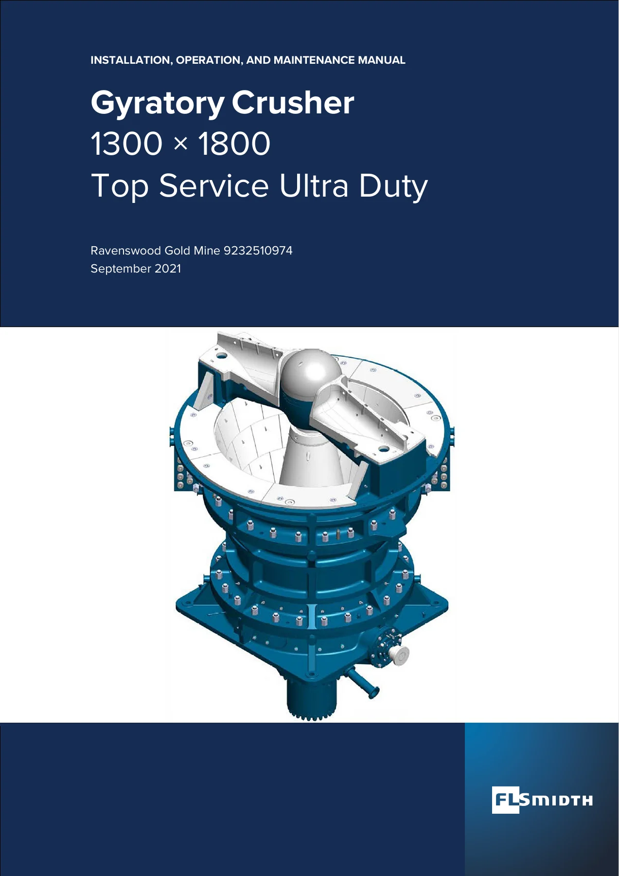
FLSmidth 1300 x 1800 TSU Gyratory Crusher Installation, Operation and Maintenance Manual — PDF page 1 preview
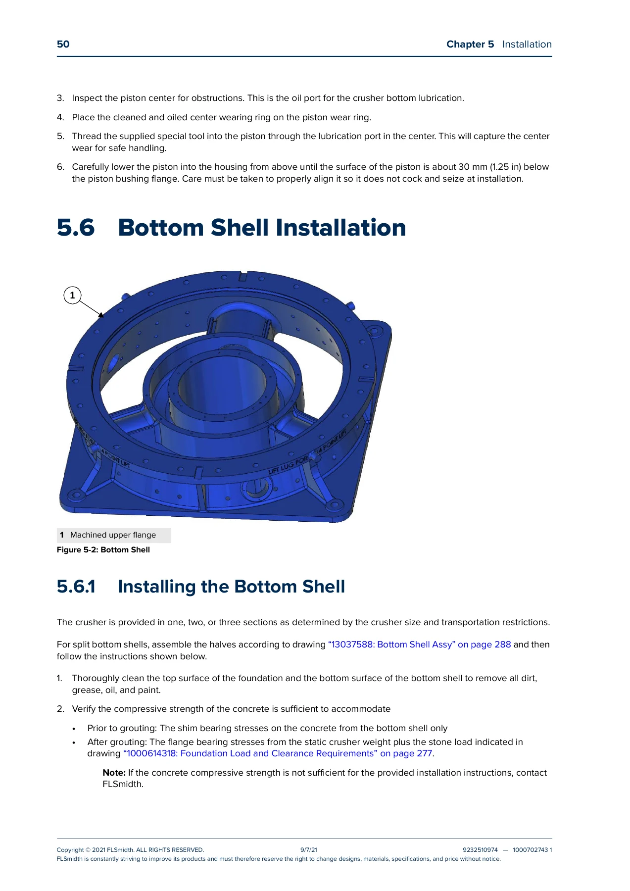
FLSmidth 1300 x 1800 TSU Gyratory Crusher Installation, Operation and Maintenance Manual — PDF page 62 preview
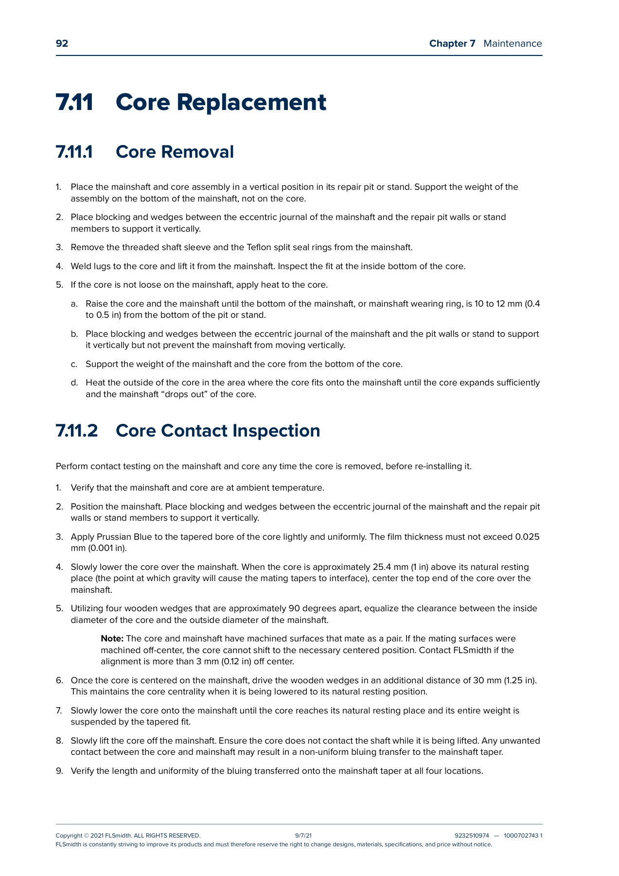
FLSmidth 1300 x 1800 TSU Gyratory Crusher Installation, Operation and Maintenance Manual — PDF page 104 preview

Instant PDF Delivery of the FLSmidth Gyratory Crusher 1300 x 1800 IOM Manual

This FLSmidth 1300 x 1800 TSU gyratory crusher installation, operation and maintenance manual is delivered as an instant PDF download – no shipping and no waiting. Open it on any laptop, tablet or smartphone in the workshop or site office, print the checklists, data sheets and drawing extracts you need for a specific job, and keep a full digital copy on hand for maintenance planning, operator training and spare parts identification. Whether you are commissioning a new 1300 x 1800 TSU, planning a mantle and concave change-out, setting up a lubrication and hydraulic maintenance schedule, or chasing down an unusual noise or a lost open-side setting, this manual puts the FLSmidth engineering documentation for the machine at your fingertips.


Reviews

There are no reviews yet.

Be the first to review “FLSmidth 1300 x 1800 TSU Gyratory Crusher Installation, Operation and Maintenance Manual”

What Our Customers Say

★★★★★ Live reviews from customers
Loading customer reviews...
0
    0
    Your Cart
    Your cart is emptyReturn to Shop
    🛒
    Recently Purchased
    🕒 verified order