Description
Sandvik DS312 Maintenance Manual 2025
This is the complete maintenance documentation set for the Sandvik DS312 underground drill rig. It covers preventive maintenance, scheduled service, component overhaul and the full set of maintenance cards used to keep the rig, its rock drills, boom, bolting head, screen handler, carrier and onboard systems running to specification. The manual is written for trained maintenance personnel and service technicians working on the DS312 in underground mining and construction environments.
File Details
- Manual type: Maintenance Manual
- Brand / manufacturer: Sandvik Mining and Construction Lyon S.A.S.
- Product type: Drill rig, model DS312
- Document ID: GUID-43159C43-3A91-4AD7-B08E-EABF667272D1
- Edition: en-US 1 (2025-06-23)
- Language: English (with a parallel Spanish translation of the same manual)
- Page count: 949 pages
- File format: PDF
Chapters Covered
- 1. Introduction — purpose of the instructions, product identification, manuals, copyright, definitions
- 2. Safety and Environmental Instructions — safety labels and signals, user obligations, product limitations, hazard zone, safeguarding, complementary protective measures, fire risk control, emission hazards, emergency procedures, maintenance safety, environment, incident reporting
- 3. Machine Description — machine orientation, main component locations (front, middle and rear sections), location of controls, main fuses and circuit breakers
- 4. Periodic Maintenance — importance of scheduled maintenance, general maintenance instructions (hydraulics, pneumatics, rock drill accumulators, electric system, batteries, tires), commissioning service advice, safety during welding, first maintenance
- 5. Maintenance Instructions — RD314 hydraulic rock drill, RD315 hydraulic rock drill, RHR50 rotary drill, B26B/B26XLB boom, SBH bolting head, SB40SH screen handler, carrier, Deutz TCD 2012 and TCD 3.6 diesel engines, safety cabin, drilling hydraulics, air circuit, CTN10 and CT28 compressors, SLU, water circuit, water pump CAT, water hose reel, electric system
- 6. Lubricants and Capacities — general oil selection, hydraulic system, rock drill shank lubrication, diesel engine, compressor, transmission and driveline oils, drill steel thread grease, lubrication grease, engine coolant, filling capacities
- 7. Additional Instructions — proximity detection system, diesel engine regeneration (Tier4/StageV/China 4), stabilizers in case of diesel engine failure, retrieving the drill rig, electric cable end limit switches, transport, lifting, washing, storing instructions
- 8. Maintenance Cards — maintenance program, instructions for reading maintenance cards, maintenance performed according to rock drill percussion hours, diesel engine hours and compressor operating hours
What This Manual Gives You
The Sandvik DS312 maintenance manual is the single reference for the scheduled upkeep of the whole rig. It walks through each maintenance card by interval — 50 h, 250 h, 500 h, 1000 h, 1500 h, 2000 h, 3000 h and 4000 h — and links every task to a numbered page where the disassembly, inspection, wear-limit check or reassembly procedure is described. Components are covered individually: flushing housings and bushings for the D38, D38B, D45 and H32 rock drill front ends, the rotation bushing and coupling, chucks and shanks, the B26B-B26XLB boom with its skids and extension tube wear limits, the SBH bolting head indexing, pulley and wire rope replacement, the SB40SH screen handler, the Dana 123 axles, and the Deutz diesel engine maintenance for both TCD 2012 and TCD 3.6 power units.
Because the DS312 is also fitted with a range of optional equipment, the manual covers the options that affect maintenance planning: the Sandvik Eclipse fire suppression system, the Ansul fire suppression system, the proximity detection system, the water hose reel, the electric cable reel, the 350 L water tank, the high-pressure cleaner, the dewatering pump and the air receiver(s). The schedule cards explain which maintenance points change when these options are installed.
Systems and Components Documented
- RD314 and RD315 hydraulic rock drills with D38, D38B, D45 and H32 front ends
- RHR50 rotary drill
- B26B and B26XLB booms
- SBH bolting head
- SB40SH screen handler
- Carrier, axles (Dana 112 and Dana 123), central articulation and brake system
- Deutz TCD 2012 and TCD 3.6 diesel engines
- CTN10 and CT28 compressors
- SLU lubrication unit and water circuit
- Drilling hydraulics, tramming hydraulics and electric system
- Safety cabin and telescopic canopy
- Fire suppression, proximity detection and access detection options
Who This Manual Is For
The DS312 Maintenance Manual is aimed at mine maintenance departments, Sandvik-trained service technicians, workshop managers and owners of DS312 drill rigs who need the manufacturer’s procedure and interval data on hand. It is not a training guide and not a general theory text — it is the task-level reference that tells you what to do, in what order, with what torque, and at what wear limit. Where relevant, the manual points to separate component documents such as the rock drill technical manual, the pressure accumulator maintenance instructions, the tire change and rim inspection manual, the cylinder maintenance manual and the air conditioning manual.
How to Use It
Each maintenance card names the task, the interval and the manual page that supports it. Use the interval that applies to your machine: percussion hours for the rock drill side, diesel engine hours for the carrier and power unit, and compressor hours for the air end. Torque values, wear limits and capacities are stated in Nm, mm, bar, litres and °C exactly as printed. The manual also documents first-service and commissioning checks, so it is relevant from the first hours of a new or rebuilt machine onward.
Get the Complete Sandvik DS312 Maintenance Manual
This PDF gives you the complete factory maintenance program for the DS312 rig — every scheduled interval, every component procedure and every torque, wear limit and capacity the machine needs. Having the correct values on hand prevents premature component failure, avoids re-work after a wrong reassembly and keeps the rig inside its safe operating envelope. The document is delivered instantly as a PDF after checkout; no shipping, no waiting, readable on a laptop, tablet or phone in the workshop and printable for the maintenance binder. Whether you are planning a 500-hour service, overhauling an RD315 front end, replacing B26XLB boom skids or setting up the annual diesel and compressor schedule, this is the reference that keeps the job in specification.
Complete PDF Bookmark Tree
Complete Bookmarks
The complete bookmarks in the “Sandvik DS312 Maintenance Manual 2025 – Complete Drill Rig Service Guide PDF” are as follows:
+DS312 Maintenance Manual Rev1 en-USp. 1
Table of Contentsp. 5
+1 Introductionp. 15
1.1 The purpose of these instructionsp. 16
+1.2 Identification of the productp. 16
1.2.1 Product type and serial numberp. 16
1.2.2 Product manufacturerp. 17
1.2.3 Marking of the productp. 17
+1.3 Manualsp. 20
1.3.1 How to identify the correct manual for the productp. 20
1.3.2 Validity of the manualsp. 21
1.3.3 Target groupp. 21
1.4 Copyright noticep. 21
1.5 Definitionsp. 21
+2 Safety and Environmental Instructionsp. 23
+2.1 Safety labels, safety messages and signalsp. 24
2.1.1 Signal wordsp. 24
2.1.2 General hazard symbolp. 24
2.1.3 Mandatory action symbolsp. 24
2.1.4 Prohibited action symbolsp. 26
2.1.5 Hazard symbolsp. 26
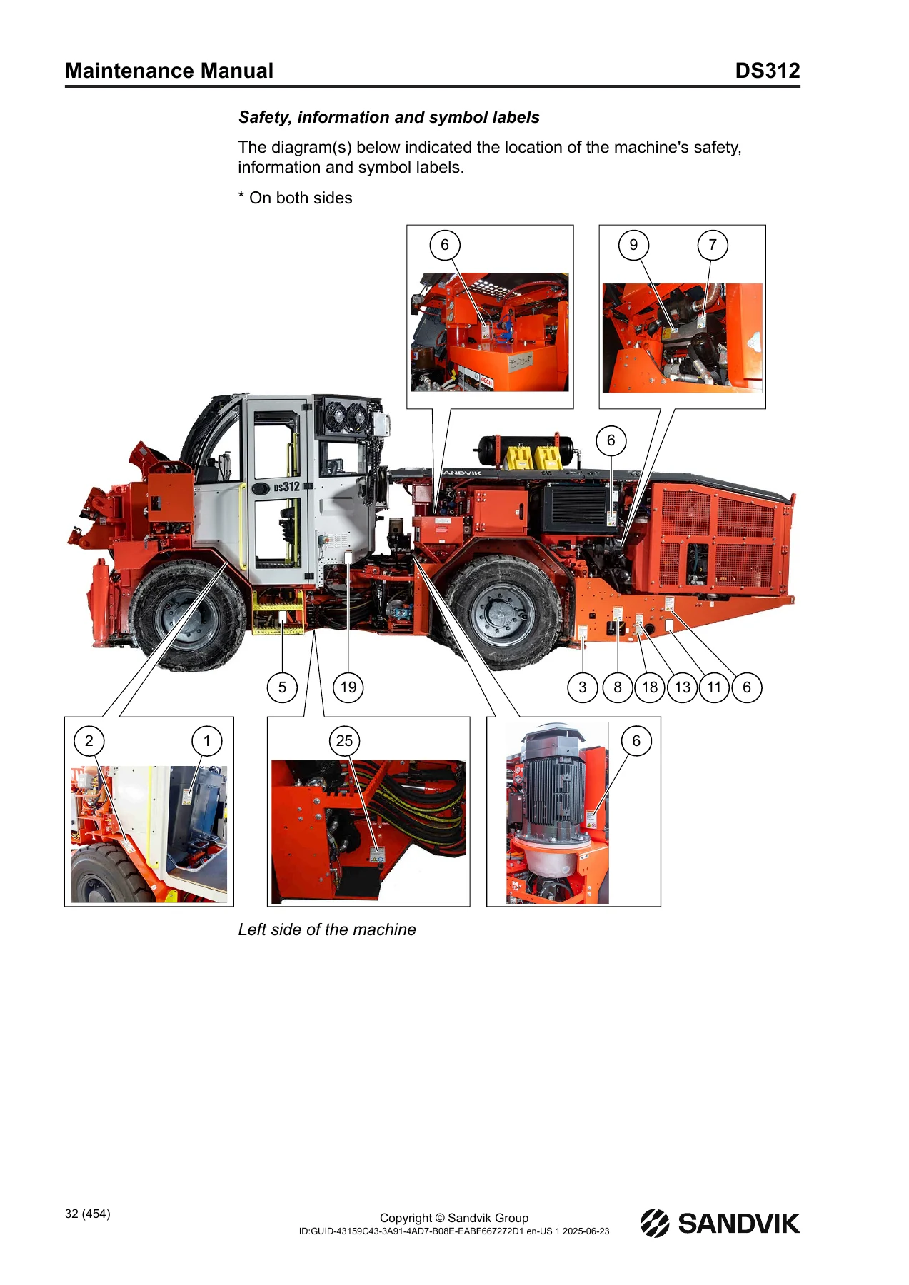
2.1.6 Labels on the productp. 29
2.1.7 Visual and audible signalsp. 39
+2.2 User obligationsp. 40
2.2.1 Managing work related hazardsp. 41
2.2.2 Scheduled safety inspections and preventive maintenancep. 41
2.2.3 Personal protective equipmentp. 42
+2.3 Product limitationsp. 42
2.3.1 Expected lifetime of the unit and its componentsp. 42
2.3.2 Intended usep. 43
2.3.3 Prohibited usep. 43
2.3.4 Center of gravityp. 43
2.3.5 Maximum inclination anglesp. 44
2.3.6 Operator visibilityp. 45
2.3.7 Modificationsp. 48
2.4 Hazard zonep. 49
+2.5 Safeguardingp. 52
2.5.1 Guardsp. 52
+2.5.2 Protective devicesp. 54
2.5.2.1 External protective devicesp. 59
2.5.3 Safety functionsp. 59
+2.6 Complementary protective measuresp. 60
2.6.1 Use of emergency stop functionp. 60
2.6.2 Use of emergency/parking or ABA brakesp. 62
2.6.3 Isolation and energy dissipationp. 64
2.6.4 Use of batteries master switch and circuit breakerp. 65
2.6.5 Proximity detection system interface (optional)p. 67
2.6.6 Access detections (optional)p. 67
2.6.7 Inhibition switchesp. 69
2.6.8 Emergency exitp. 72
2.6.9 Safe access to machine and three-point supportp. 72
+2.7 Fire risk control measuresp. 74
2.7.1 In case of firep. 74
2.7.2 Fire preventionp. 75
2.7.3 Fire retardant and flammable materialsp. 75
+2.7.4 Fire suppressionp. 76
2.7.4.1 Fire extinguisher(s)p. 76
2.7.4.2 Ansul fire suppression system (optional)p. 77
2.7.4.3 Eclipse fire suppression system (optional)p. 79
2.7.5 After a firep. 83
+2.8 Protection against emission hazardsp. 83
2.8.1 Noisep. 83
2.8.2 Vibrationp. 84
2.8.3 Dustp. 84
2.8.4 Diesel emissionsp. 85
2.9 Emergency proceduresp. 85
+2.10 Safety considerations for maintenancep. 87
2.10.1 Daily inspections and tasks for operatorsp. 88
2.10.2 Tasks which require definite technical skills and maintenance trainingp. 88
2.10.3 Instructions for maintenance by multiple personsp. 89
+2.11 Environmentp. 90
2.11.1 Decommissioningp. 90
2.11.2 Dismantlingp. 91
2.11.3 Disposalp. 92
2.12 Potential product related hazards identified by the userp. 94
2.13 Incident reportingp. 94
+3 Machine Descriptionp. 95
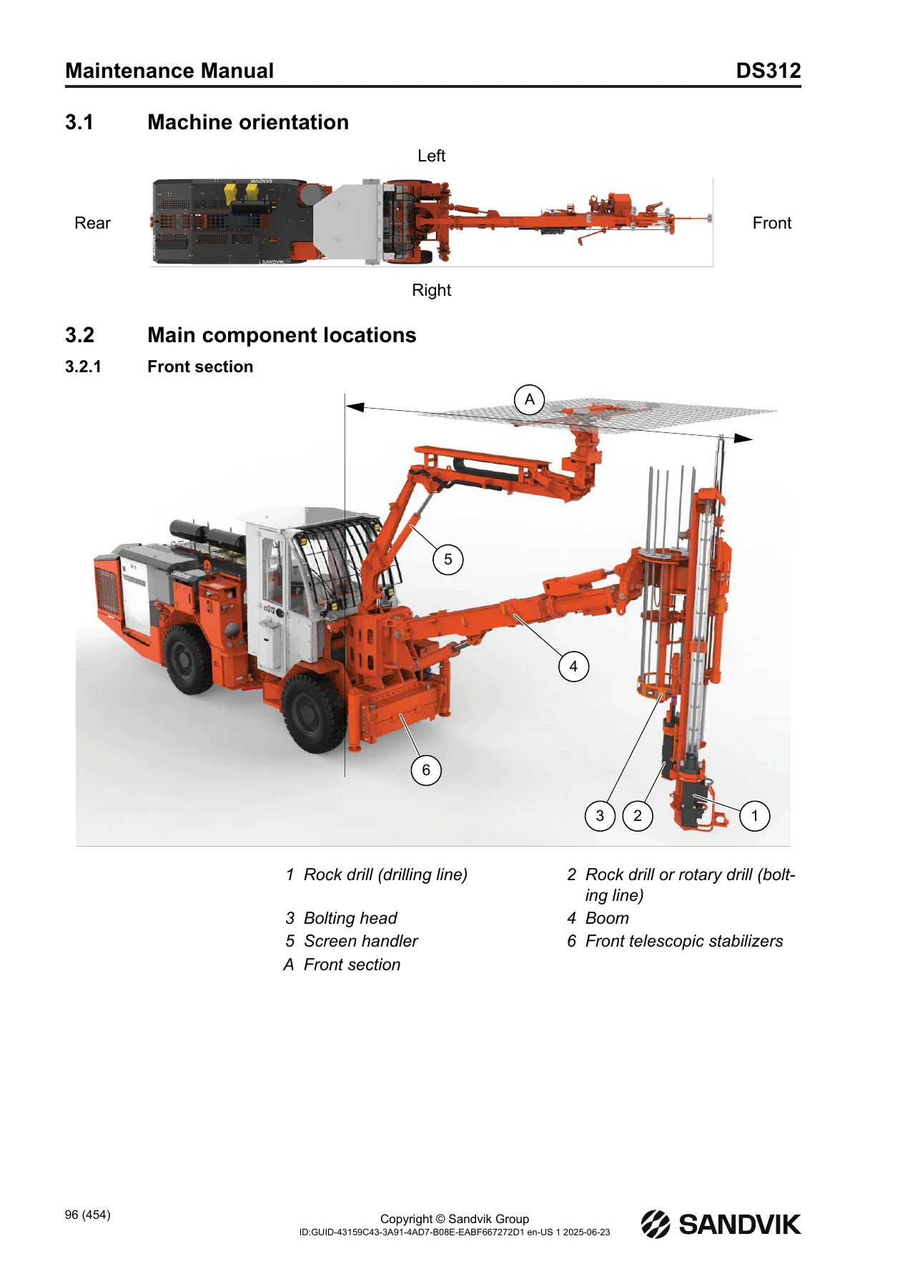
3.1 Machine orientationp. 96
+3.2 Main component locationsp. 96
+3.2.1 Front sectionp. 96
3.2.1.1 Rock drillsp. 97
3.2.1.2 B26B-B26XLB Boomp. 98
3.2.1.3 Boom SB70S (optional)p. 99
3.2.1.4 SBH bolting headp. 99
3.2.1.5 SB40SH Screem handlerp. 100
+3.2.2 Middle sectionp. 101
3.2.2.1 Tramming compartmentp. 102
3.2.2.2 Drilling compartmentp. 104
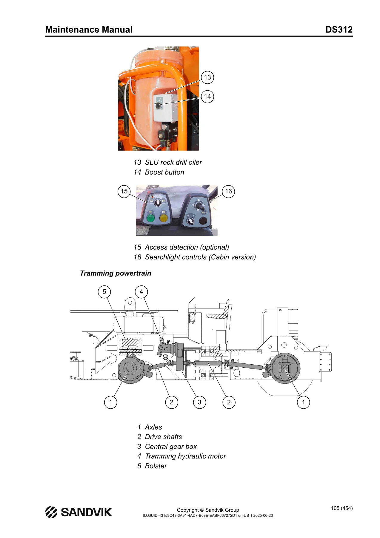
3.2.2.3 Tramming powertrainp. 105
3.2.2.4 Canopy lightsp. 106
3.2.2.5 High pressure cleaning device with hose reel (optional)p. 107
3.2.2.6 Socket below cabin (optional)p. 107
+3.2.3 Rear sectionp. 108
3.2.3.1 Drilling hydraulic systemp. 109
3.2.3.2 Diesel power pack, Deutz TCD2012 Tier3p. 110
3.2.3.3 Diesel power pack, Deutz TCD 3.6 Tier4 / StageVp. 111
3.2.3.4 Water circuitp. 112
3.2.3.5 Water circuit with 350l water tank (optional)p. 113
3.2.3.6 Air circuitp. 114
+3.3 Location of controlsp. 115
+3.3.1 Tramming compartmentp. 115
3.3.1.1 Tramming control panelp. 117
3.3.1.2 Emergency/parking or ABA (optional) brakesp. 118
3.3.1.3 Horn, tramming direction and speed selector joystickp. 119
3.3.1.4 Foot pedalsp. 120
3.3.1.5 Safety canopy and telescopic stabilizer controlsp. 121
3.3.1.6 Electric cable reel controlsp. 122
3.3.1.7 Unbraking hand pump (optional)p. 123
3.3.1.8 Under canopy controlsp. 125
3.3.1.9 Cabin controlsp. 125
3.3.1.10 Air conditioning controlsp. 126
+3.3.2 Drilling compartmentp. 127
3.3.2.1 Boom controlsp. 128
3.3.2.2 Drilling controlsp. 130
3.3.2.3 Adjustment knobp. 132
3.3.2.4 Screen handlerp. 132
3.3.2.5 Switches and joystickp. 134
3.3.2.6 Pressure gaugesp. 137
3.3.2.7 Pressure test pointsp. 137
3.3.2.8 SLU rock drill oilerp. 138
3.3.2.9 Air mist (optional)p. 138
3.3.2.10 Flushing flow control (optional)p. 139
3.3.2.11 QN panelp. 140
3.3.2.12 Access detection (optional)p. 142
3.3.2.13 Cartridge injection gun (optional)p. 143
3.3.2.14 SBI bolting instrumentation (optional)p. 143
+3.4 Main fuses and circuit breakersp. 144
3.4.1 Standard electric cabinetp. 144
3.4.2 Fuses and circuit breakersp. 147
+3.4.3 Fault current and overprotection switchgear VYK (optional)p. 147
3.4.3.1 VYK equipped with pilot line (optional)p. 149
3.4.3.2 Fault current testp. 149
3.4.3.3 Electric powerp. 150
+4 Periodic Maintenancep. 153
4.1 Importance of scheduled maintenancep. 154
+4.2 General maintenance instructionsp. 155
4.2.1 Maintenance of the hydraulicsp. 155
4.2.2 Pneumatic system maintenancep. 157
4.2.3 Maintenance of the rock drill pressure accumulatorsp. 157
+4.2.4 Electric system maintenance – Safety instructionsp. 158
4.2.4.1 Performing maintenance on electrical componentsp. 158
4.2.4.2 Modifications to electrical systemsp. 159
+4.2.5 Maintenance of the batteriesp. 159
4.2.5.1 Disconnecting and connecting of the cable shoesp. 161
4.2.6 Tire maintenancep. 162
4.3 Commissioning service advicep. 163
4.4 Safety during weldingp. 164
+4.5 First maintenancep. 165
4.5.1 Initial service performed according to rock drill percussion hoursp. 165
4.5.2 Initial service performed according to diesel engine hoursp. 166
4.5.3 Initial service performed according to compressor operating hoursp. 167
+5 Maintenance Instructionsp. 169
+5.1 Generalp. 170
5.1.1 Washing the drill rigp. 170
5.1.2 Checking the steel structuresp. 170
5.1.3 Inspecting and testing all cylinders and related componentsp. 170
+5.2 Hydraulic rock drill RD314p. 171
5.2.1 Checking the flushing housing and its componentsp. 171
5.2.2 Removing the flushing housing, D45p. 171
5.2.3 Wear limits for the flushing housing bushings, D45p. 172
5.2.4 Disassembling the flushing housing, D45p. 173
5.2.5 Changing the flushing housing bushings, D45p. 173
5.2.6 Assembling the flushing housing, D45p. 178
5.2.7 Removing the flushing housing, D38p. 179
5.2.8 Wear limits for the flushing housing bushings, D38p. 180
5.2.9 Disassembling the flushing housing, D38p. 181
5.2.10 Changing the flushing housing bushings, D38p. 185
5.2.11 Assembling the flushing housing, D38p. 186
5.2.12 Checking the rotation bushing bearingsp. 190
5.2.13 Checking the couplingp. 190
5.2.14 Checking the rotation bushingp. 191
+5.2.15 Checking the chuckp. 191
5.2.15.1 Replacing the chuckp. 192
5.2.16 Checking the shankp. 192
5.2.17 Installing the flushing housingp. 193
5.2.18 Checking the accumulator filling valve and cover plug conditionp. 194
5.2.19 Checking the accumulator pressurep. 195
+5.2.20 Checking the tightness of the boltsp. 195
5.2.20.1 Accumulator boltsp. 195
5.2.20.2 Flushing housing mounting boltsp. 196
5.2.20.3 Flushing housing front cover boltsp. 197
5.2.20.4 Flushing line fitting flange boltsp. 197
5.2.20.5 Rotation motor boltsp. 198
5.2.20.6 Rotation motor flange boltsp. 198
5.2.20.7 Rear cover boltsp. 199
5.2.20.8 Rock drill mounting boltsp. 200
5.2.21 Rock drill overhaulp. 201
5.2.22 After rock drill servicep. 201
+5.3 Hydraulic rock drill RD315p. 201
5.3.1 Checking the rock drill front end and its componentsp. 201
+5.3.2 RD315 D38 Flushing housingp. 203
5.3.2.1 Removing the flushing housing, D38p. 203
5.3.2.2 Wear limits for the flushing housing bushings, D38p. 203
5.3.2.3 Disassembling the flushing housing, D38p. 204
5.3.2.4 Replacing the flushing housing bushings, D38p. 208
5.3.2.5 Assembling the flushing housing, D38p. 209
+5.3.3 RD315 D38B Bearing housingp. 213
5.3.3.1 Removing the bearing housing, D38Bp. 213
5.3.3.2 Wear limits for the bearing housing bushings, D38Bp. 213
5.3.3.3 Disassembling the bearing housing, D38Bp. 214
5.3.3.4 Replacing the bearing housing bushings, D38Bp. 216
5.3.3.5 Assembling the bearing housing, D38Bp. 217
+5.3.4 RD315 D45 Flushing housingp. 219
5.3.4.1 Removing the flushing housing, D45p. 219
5.3.4.2 Wear limits for the flushing housing bushings, D45p. 219
5.3.4.3 Disassembling the flushing housing, D45p. 220
5.3.4.4 Replacing the flushing housing bushings, D45p. 221
5.3.4.5 Assembling the flushing housing, D45p. 226
+5.3.5 RD315 H32 Front coverp. 227
5.3.5.1 Removing the front cover, H32p. 227
5.3.5.2 Wear limits for the front cover bushing, H32p. 228
5.3.5.3 Disassembling the front cover, H32p. 228
5.3.5.4 Replacing the front cover bushing and hex chuck, H32p. 229
5.3.5.5 Assembling the front cover, H32p. 231
5.3.6 Checking the rotation bushing bearingsp. 231
5.3.7 Checking the couplingp. 232
5.3.8 Checking the rotation bushingp. 232
+5.3.9 Checking the chuckp. 233
5.3.9.1 Replacing the chuckp. 234
5.3.10 Checking the shankp. 234
+5.3.11 Installing the front endp. 235
5.3.11.1 RD315 D38 Flushing housingp. 235
5.3.11.2 RD315 D38B Bearing housingp. 236
5.3.11.3 RD315 D45 Flushing housingp. 237
5.3.11.4 RD315 H32 Front coverp. 237
5.3.12 Checking the accumulator filling valve and cover plug conditionp. 238
5.3.13 Checking the accumulator pressurep. 239
+5.3.14 Checking the tightness of the boltsp. 239
5.3.14.1 Accumulator boltsp. 239
5.3.14.2 Front end mounting boltsp. 240
5.3.14.3 Bearing housing / flushing housing front cover boltsp. 241
5.3.14.4 RD315 D38 Flushing line fitting flange boltsp. 242
5.3.14.5 Rotation motor boltsp. 243
5.3.14.6 Rotation motor flange boltsp. 243
5.3.14.7 Rear cover boltsp. 244
5.3.14.8 Rock drill mounting boltsp. 244
5.3.15 Rock drill overhaulp. 245
5.3.16 After rock drill servicep. 245
+5.4 Rotary drill RHR50p. 246
5.4.1 Checking the rod driver conditionp. 246
5.4.2 Replacing the rod driver water flushing seals (optional)p. 247
5.4.3 Checking the water supply flange sealp. 248
5.4.4 Checking the oil levelp. 249
5.4.5 Changing the oilp. 250
5.4.6 Checking and replacing all damaged partsp. 250
+5.5 Boom B26B-B26XLBp. 250
5.5.1 Checking the tightening torquesp. 250
5.5.2 Checking the expendable pinp. 251
5.5.3 Checking the condition of all equipmentp. 251
5.5.4 Checking the clearance between skids and tubep. 252
5.5.5 Adjusting the clearance between the skids and tubep. 253
5.5.6 Checking the extension tube wearp. 254
5.5.7 Checking the rotary actuatorsp. 254
5.5.8 Checking the condition of weldingsp. 255
5.5.9 Checking the condition of boomp. 255
+5.6 Bolting head SBHp. 255
5.6.1 Checking the condition of the rock drill cradlesp. 255
5.6.2 Checking the tightening torquesp. 255
5.6.3 Checking the 2 position bolting head indexingp. 255
5.6.4 Checking the 3 position bolting head indexingp. 260
5.6.5 Checking the condition of the pulleysp. 262
5.6.6 Checking the condition of the pulling wheelp. 263
5.6.7 Checking the condition of the rails and skidsp. 263
5.6.8 Replacing the skidsp. 266
5.6.9 Replacing the railsp. 267
+5.6.10 Replacing the wire ropesp. 268
5.6.10.1 Removing the feed thrust (forward) wire ropep. 268
5.6.10.2 Removing the feed return (backward) wire ropep. 270
5.6.10.3 Adjusting the wire rope tensionp. 272
5.6.11 Checking the condition of weldingsp. 274
5.6.12 Replacing the pulley bearingp. 276
5.6.13 Replacing the pulling wheel bearingp. 277
5.6.14 Replacing the feed indexing bronze bushingsp. 278
5.6.15 Replacing the bolt carousel bronze bushingsp. 280
5.6.16 Performing the overall inspection and testingp. 282
+5.7 Screen handler SB40SHp. 282
5.7.1 Checking the tightening torquesp. 282
5.7.2 Checking the expendable pinp. 283
5.7.3 Checking the clearance between the boom extension tube and armaturep. 284
5.7.4 Checking the condition of weldingsp. 287
5.7.5 Checking the overall condition of the equipmentp. 287
5.7.6 Overall inspection and reconditioningp. 287
+5.8 Carrierp. 288
+5.8.1 Lubricating the carrier from the greasing pointsp. 288
5.8.1.1 Central greasing system (optional)p. 288
5.8.2 Checking the tightness of bolts and nuts and expendable pins of the power trainp. 290
5.8.3 Checking and adjusting the pressure of the brake accumulatorsp. 291
5.8.4 Checking the condition of the steering wheel systemp. 294
5.8.5 Changing the tramming circuit oilp. 294
5.8.6 Replacing the breather of the tramming tankp. 296
5.8.7 Replacing the tramming circuit oil filterp. 296
5.8.8 Replacing the breather of the fuel tankp. 297
5.8.9 Checking the gearbox oil levelp. 297
5.8.10 Changing the gearbox oilp. 298
5.8.11 Changing the cable reel gearbox oilp. 299
5.8.12 Lubricating bearings of the cable guide rollersp. 299
5.8.13 Checking the axle oil levels, Dana 123p. 300
5.8.14 Changing the axle oils, Dana 123p. 301
5.8.15 Checking the brake disks for the wear, Dana 123p. 301
5.8.16 Performing the service brake dynamic testp. 303
5.8.17 Checking the central articulation clearancep. 304
5.8.18 Checking the axle bolster clearancep. 304
5.8.19 Overall inspection and reconditioningp. 304
5.8.20 Servicing the Sandvik Eclipse fire suppression system (optional), every 6 monthsp. 305
5.8.21 Servicing the Sandvik Eclipse fire suppression system (optional), once a yearp. 305
5.8.22 Servicing the Sandvik Eclipse fire suppression system (optional), every 3 and 5 yearsp. 306
+5.9 Diesel engine Deutz TCD 2012p. 308
5.9.1 Changing the engine oilp. 308
5.9.2 Replacing the engine oil filterp. 309
5.9.3 Replacing the fuel filterp. 309
5.9.4 Replacing the fuel prefilterp. 311
5.9.5 Venting the fuel systemp. 312
5.9.6 Checking the engine coolantp. 313
5.9.7 Changing the engine coolantp. 314
5.9.8 Replacing the air filter cartridgep. 316
5.9.9 Replacing the air filter safety cartridgep. 317
5.9.10 Checking the condition of the V-rib beltp. 317
5.9.11 Replacing the V-rib beltp. 318
5.9.12 Draining the charge air coolerp. 318
5.9.13 Checking the condition of the cold starting devicep. 319
5.9.14 Checking the engine mountingp. 319
5.9.15 Checking the condition of the fastenings, hose unions and clipsp. 319
5.9.16 Checking the operation of the engine monitoring and warning systemp. 319
+5.10 Diesel engine Deutz TCD 3.6p. 319
5.10.1 Changing the engine oilp. 319
5.10.2 Replacing the engine oil filterp. 320
5.10.3 Replacing the fuel filterp. 321
5.10.4 Replacing the fuel pre-filterp. 322
5.10.5 Venting the fuel systemp. 323
5.10.6 Checking the engine coolantp. 323
5.10.7 Changing the engine coolantp. 324
5.10.8 Replacing the air filter cartridgep. 326
5.10.9 Replacing the air filter safety cartridgep. 327
5.10.10 Checking the condition of the V-rib beltp. 327
5.10.11 Replacing the V-rib belt and tension pulleyp. 328
5.10.12 Replacing the AdBlue® supply pump filter (Tier4)p. 328
5.10.13 Replacing the sieve and fuel filters, and the breather of the urea tank (Tier4)p. 329
5.10.14 Draining the charge air coolerp. 330
5.10.15 Checking the condition of the cold starting devicep. 330
5.10.16 Checking the engine mountingp. 330
5.10.17 Checking the condition of the fastenings, hose unions and clipsp. 330
5.10.18 Checking the operation of the engine monitoring and warning systemp. 330
5.10.19 Replacing the diesel particle filter (Tier4 and China4)p. 331
+5.11 Safety cabinp. 331
5.11.1 Cleaning the control devicesp. 331
5.11.2 Checking the operation of the air conditioningp. 331
5.11.3 Cleaning the active carbon filter and condenserp. 331
5.11.4 Checking the tightness of the air conditioning compressor beltp. 331
5.11.5 Servicing the air conditioningp. 332
5.11.6 Checking the condition of the heater (Webasto)p. 332
+5.12 Drilling hydraulicsp. 333
5.12.1 Replacing the pressure filterp. 333
5.12.2 Replacing the breather element of the drilling tankp. 334
5.12.3 Replacing the return oil filterp. 334
5.12.4 Changing the drilling circuit hydraulic oilp. 335
+5.13 Air circuitp. 336
5.13.1 Checking the condition of the air receiver(s) (optional)p. 336
+5.14 Compressor CTN10p. 336
5.14.1 Procedures prior to compressor maintenancep. 336
5.14.2 Replacing the compressor oil filterp. 337
5.14.3 Changing the compressor oilp. 337
5.14.4 Checking and retightening main motor cablesp. 338
5.14.5 Replacing the compressor air filtersp. 338
5.14.6 Replacing the compressor beltsp. 339
5.14.7 Cleaning the cooler externallyp. 339
5.14.8 Cleaning the compressor externally with a clothp. 339
5.14.9 Replacing the compressor oil separator cartridgep. 340
5.14.10 Cleaning the oil return linep. 340
5.14.11 Checking the operation of the compressor relief valvep. 341
+5.14.12 Replacing the seal kit of the inlet valvep. 341
5.14.12.1 Disassembling the inlet valvep. 341
5.14.12.2 Reassembling the inlet valvep. 346
5.14.13 Checking the protective functions of the temperature monitoring systemp. 348
5.14.14 Checking the condition of the compressor hosesp. 349
5.14.15 Replacing the blow-down valvep. 349
5.14.16 Replacing the oil thermostatp. 350
5.14.17 Replacing the shaft seal kitp. 350
5.14.18 Replacing the air endp. 350
5.14.19 Checking the function of the thermometer safety limitsp. 350
+5.15 Compressor CT28 (optional)p. 350
5.15.1 Procedures prior to compressor maintenancep. 350
5.15.2 Changing the compressor oilp. 351
5.15.3 Replacing the compressor oil filterp. 352
5.15.4 Checking and retightening main motor cablesp. 352
5.15.5 Cleaning the compressor externally with a clothp. 352
5.15.6 Replacing the compressor air filtersp. 352
5.15.7 Replacing the compressor beltsp. 353
5.15.8 Cleaning the cooler externallyp. 353
5.15.9 Replacing the compressor oil separator cartridge, wing nut and discharge valve sealsp. 354
5.15.10 Cleaning the oil return linep. 355
5.15.11 Replacing the screen for oil return, fittings and gasketp. 355
5.15.12 Checking the operation of the compressor relief valvep. 355
5.15.13 Lubricating the electric motor bearingsp. 355
5.15.14 Replacing the seal kit of the inlet valvep. 355
5.15.15 Checking the protective functions of the temperature monitoring systemp. 356
5.15.16 Checking the condition of the compressor hosesp. 357
5.15.17 Replacing the blow-down valvep. 357
5.15.18 Replacing the oil thermostatp. 358
5.15.19 Replacing the motor bearingsp. 358
5.15.20 Replacing the shaft seal kitp. 359
5.15.21 Replacing the air endp. 359
+5.16 SLUp. 359
5.16.1 Draining the condensed waterp. 359
5.16.2 Checking the condition of the water separatorp. 359
5.16.3 Replacing the water separator filter elementp. 360
5.16.4 Cleaning the tankp. 361
5.16.5 Replacing the breatherp. 361
5.16.6 Checking the function of the monitoring systemp. 362
+5.17 Water circuitp. 362
5.17.1 Venting the water pumpp. 362
5.17.2 Checking the condition and operation of the main componentsp. 362
5.17.3 Cleaning the water filter elementp. 364
5.17.4 Lubricating the water pump couplingp. 364
+5.18 Water pump CATp. 365
5.18.1 Checking the condition of the water pump CATp. 365
5.18.2 Changing the water pump oilp. 365
5.18.3 Replacing the water pump sealsp. 365
5.18.4 Replacing the water pump valvesp. 365
+5.19 Water hose reel (optional)p. 366
5.19.1 Lubricating the bearings of the cable guide rollersp. 366
5.19.2 Lubricating the hose reel spooling systemp. 366
5.19.3 Checking the guide rollers of water hose reelp. 367
5.19.4 Lubricating the chains of the water hose reelp. 367
5.19.5 Checking the tightness of the water hose reel chainsp. 368
+5.20 Electric systemp. 369
5.20.1 Checking the condition of the shaft sealsp. 369
5.20.2 Electric system maintenance – Safety instructionsp. 369
5.20.3 Checking the electric cabinets and boxesp. 369
5.20.4 Checking the condition of the cables, cable mounting and grommetsp. 369
5.20.5 Checking the operation of the fault current protector switchp. 369
5.20.6 Checking the power supply cablep. 369
5.20.7 Checking the water drainage holesp. 370
5.20.8 Checking the seal bushingsp. 370
5.20.9 Checking the contactors of the plug connectorsp. 370
5.20.10 Applying protective agent to the connectionsp. 370
5.20.11 Checking the operation of the safety device sensorsp. 370
5.20.12 Cleaning the electric motorsp. 370
5.20.13 Checking the condition of the batteries and cable connectorsp. 370
5.20.14 Checking the electric motor mountingp. 371
5.20.15 Checking the electric motor bearingsp. 371
5.20.16 Checking the condition of the power pack electric motor slip ring contact systemp. 371
5.20.17 Checking the motor and other screw-mounting terminalsp. 372
+6 Lubricants and Capacitiesp. 373
6.1 Generalp. 374
6.2 Hydraulic systemp. 379
6.3 Rock drill shank lubricationp. 383
6.4 Diesel enginep. 384
6.5 Compressorp. 385
6.6 Transmission and driveline oilsp. 387
6.7 Drill steel thread greasep. 388
6.8 Lubrication greasep. 388
6.9 Engine coolantp. 389
6.10 Filling capacitiesp. 390
+7 Additional Instructionsp. 393
+7.1 Proximity detection system (optional)p. 394
7.1.1 Operating the proximity detection system interfacep. 394
7.1.2 Operation in case of detectionp. 395
7.1.3 Speed brake interlock (SBI) for runaway situationp. 397
+7.2 Diesel engine regeneration (Tier4, StageV and China 4 only)p. 399
7.2.1 Diesel Particle Filter regeneration procedurep. 399
7.2.2 Emission related legislationp. 401
7.3 Using stabilizers in case of diesel engine failurep. 402
+7.4 Retrieving the drill rigp. 407
7.4.1 Short distance towingp. 407
+7.4.2 Long distance towingp. 414
7.4.2.1 Towing with the engine in operating conditionp. 414
7.4.2.2 Towing with a faulty enginep. 414
7.5 Electric cable end limit switchesp. 415
7.6 Transportp. 416
+7.7 Liftingp. 417
7.7.1 Load liftingp. 420
7.7.2 Lowering and raising equipment through a mine shaftp. 423
7.8 Washingp. 423
7.9 Storing instructionsp. 426
+8 Maintenance Cardsp. 429
8.1 Maintenance programp. 430
8.2 Instructions for reading maintenance cardsp. 431
+8.3 Maintenance performed according to rock drill percussion hoursp. 432
8.3.1 Every 50 hoursp. 432
8.3.2 Every 250 hoursp. 435
8.3.3 Every 500 hoursp. 436
8.3.4 Every 1000 hoursp. 437
8.3.5 Every 1500 hoursp. 439
8.3.6 Every 3000 hoursp. 440
+8.4 Maintenance performed according to diesel engine hoursp. 441
8.4.1 Every 50 hoursp. 441
8.4.2 Every 250 hoursp. 442
8.4.3 Every 500 hoursp. 443
8.4.4 Every 1000 hoursp. 444
8.4.5 Every 2000 hoursp. 446
8.4.6 Every 3000 hoursp. 447
+8.5 Maintenance performed according to compressor operating hoursp. 448
8.5.1 Every 500 hoursp. 448
8.5.2 Every 1000 hoursp. 450
8.5.3 Every 2000 hoursp. 451
8.5.4 Every 4000 hoursp. 452
+DS312 Maintenance Manual Rev1 es-ESp. 455
Índice de contenidosp. 459
+1 Introducciónp. 469
1.1 Objetivo de estas instruccionesp. 470
+1.2 Identificación del productop. 470
1.2.1 Tipo de producto y número de seriep. 470
1.2.2 Fabricante del productop. 471
1.2.3 Marcado del productop. 471
+1.3 Manualesp. 474
1.3.1 Identificación del manual correcto para el productop. 474
1.3.2 Validez de los manualesp. 475
1.3.3 Grupo objetivop. 475
1.4 Nota de copyrightp. 475
1.5 Definicionesp. 475
+2 Instrucciones de seguridad y protección del medio ambientep. 477
+2.1 Etiquetas de seguridad, mensajes de seguridad y señalesp. 478
2.1.1 Términos de advertenciap. 478
2.1.2 Símbolo de peligro generalp. 478
2.1.3 Símbolos de acción obligatoriap. 478
2.1.4 Símbolos de acción prohibidap. 480
2.1.5 Símbolos de peligrop. 480
2.1.6 Etiquetas en el productop. 484
2.1.7 Señales visuales y acústicasp. 493
+2.2 Obligaciones del usuariop. 494
2.2.1 Gestión de peligros relacionados con el trabajop. 495
2.2.2 Inspecciones de seguridad programadas y mantenimiento preventivop. 495
2.2.3 Equipos de protección individualp. 496
+2.3 Limitaciones del productop. 496
2.3.1 Vida útil prevista de la unidad y sus componentesp. 496
2.3.2 Uso previstop. 497
2.3.3 Uso prohibidop. 497
2.3.4 Centro de gravedadp. 498
2.3.5 Ángulos máximos de inclinaciónp. 499
2.3.6 Visibilidad del operariop. 500
2.3.7 Modificacionesp. 503
2.4 Zona de peligrop. 504
+2.5 Proteccionesp. 507
2.5.1 Proteccionesp. 507
+2.5.2 Dispositivos de protecciónp. 509
2.5.2.1 Dispositivos de protección externosp. 515
2.5.3 Funciones de seguridadp. 515
+2.6 Medidas de protección complementariasp. 516
2.6.1 Uso de la función de parada de emergenciap. 516
2.6.2 Uso de los frenos de emergencia/estacionamiento o ABAp. 518
2.6.3 Aislamiento y disipación de energíap. 520
2.6.4 Uso del interruptor principal de la batería y el disyuntorp. 522
2.6.5 Interfaz del sistema de detección de proximidad (opcional)p. 524
2.6.6 Detecciones de acceso (opcional)p. 524
2.6.7 Interruptores de inhibiciónp. 527
2.6.8 Salida de emergenciap. 529
2.6.9 Acceso seguro a la máquina y apoyo de tres puntosp. 529
+2.7 Medidas de control del riesgo de incendiosp. 531
2.7.1 En caso de incendiop. 532
2.7.2 Prevención de incendiosp. 532
2.7.3 Materiales ignífugos e inflamablesp. 533
+2.7.4 Extinción de incendiosp. 533
2.7.4.1 Extintores de incendiosp. 533
2.7.4.2 Sistema de extinción de incendios Ansul (opcional)p. 536
2.7.4.3 Sistema de extinción de incendios Eclipse (opcional)p. 538
2.7.5 Después de un incendiop. 541
+2.8 Protección contra los peligros relativos a las emisionesp. 542
2.8.1 Ruidop. 542
2.8.2 Vibraciónp. 542
2.8.3 Polvop. 543
2.8.4 Emisiones diéselp. 544
2.9 Procedimientos de emergenciap. 544
+2.10 Consideraciones de seguridad para el mantenimientop. 546
2.10.1 Inspecciones y tareas diarias para operariosp. 547
2.10.2 Tareas que requieren formación específica en mantenimiento y habilidades técnicas especialesp. 547
2.10.3 Instrucciones para el mantenimiento por parte de varias personasp. 548
+2.11 Medio ambientep. 549
2.11.1 Retirada del serviciop. 549
2.11.2 Desmontajep. 550
2.11.3 Desechop. 551
2.12 Peligros potenciales relacionados con el producto identificados por el usuariop. 553
2.13 Informar sobre los incidentesp. 554
+3 Descripción de la máquinap. 555
3.1 Orientación de la máquinap. 556
+3.2 Ubicaciones de los componentes principalesp. 556
+3.2.1 Sección delanterap. 556
3.2.1.1 Martillosp. 557
3.2.1.2 Brazo B26B-B26XLBp. 558
3.2.1.3 Brazo SB70S (opcional)p. 559
3.2.1.4 Cabezal de empernado SBHp. 560
3.2.1.5 Manipulador de criba SB40SHp. 561
+3.2.2 Sección intermediap. 562
3.2.2.1 Compartimento de desplazamientop. 563
3.2.2.2 Compartimento de perforaciónp. 565
3.2.2.3 Transmisión de desplazamientop. 567
3.2.2.4 Luces del techo de cabinap. 567
3.2.2.5 Dispositivo de limpieza a alta presión con enrollador (opcional)p. 568
3.2.2.6 Toma debajo de la cabina (opcional)p. 569
+3.2.3 Sección traserap. 569
3.2.3.1 Sistema hidráulico de perforaciónp. 571
3.2.3.2 Unidad de alimentación diésel, Deutz TCD2012 Tier3p. 572
3.2.3.3 Unidad de alimentación diésel, Deutz TCD 3.6 Tier4 / StageVp. 573
3.2.3.4 Circuito de aguap. 574
3.2.3.5 Circuito de agua con depósito de agua de 350 L (opcional)p. 575
3.2.3.6 Circuito de airep. 576
+3.3 Ubicación de los controlesp. 577
+3.3.1 Compartimento de desplazamientop. 577
3.3.1.1 Panel de control de desplazamientop. 579
3.3.1.2 Frenos de emergencia/estacionamiento o ABA (opcionales)p. 580
3.3.1.3 Bocina, palanca selectora de velocidad y dirección de desplazamientop. 581
3.3.1.4 Pedales de piep. 582
3.3.1.5 Techo de cabina de seguridad y mandos de los estabilizadores telescópicosp. 583
3.3.1.6 Controles del enrollador de cable eléctricop. 584
3.3.1.7 Bomba manual de desfrenado (opcional)p. 585
3.3.1.8 Mandos situados debajo del teche de cabinap. 587
3.3.1.9 Controles de la cabinap. 587
3.3.1.10 Controles del aire acondicionadop. 588
+3.3.2 Compartimento de perforaciónp. 589
3.3.2.1 Controles del brazop. 591
3.3.2.2 Controles de perforaciónp. 592
3.3.2.3 Pomo de ajustep. 594
3.3.2.4 Manipulador de cribap. 594
3.3.2.5 Interruptores y joystickp. 596
3.3.2.6 Manómetrosp. 599
3.3.2.7 Puntos de prueba de presiónp. 600
3.3.2.8 engrasador de martillo perforador SLUp. 600
3.3.2.9 Barrido por vapor de aire (opcional)p. 601
3.3.2.10 Control de flujo de barrido (opcional)p. 602
3.3.2.11 Panel QNp. 603
3.3.2.12 Detección de acceso (opcional)p. 606
3.3.2.13 Pistola de inyección de cartuchos (opcional)p. 607
3.3.2.14 Instrumentación de empernado SBI (opcional)p. 607
+3.4 Fusibles principales y disyuntoresp. 608
3.4.1 Armario eléctrico estándarp. 608
3.4.2 Fusibles y disyuntoresp. 611
+3.4.3 Corriente de fallo y armario de conmutación de sobreprotección VYK (opcional)p. 611
3.4.3.1 VYK equipado con conducto piloto (opcional)p. 613
3.4.3.2 Prueba de fallo de corrientep. 613
3.4.3.3 Alimentación eléctricap. 615
+4 Mantenimiento periódicop. 617
4.1 Importancia del mantenimiento programadop. 618
+4.2 Instrucciones generales de mantenimientop. 620
4.2.1 Mantenimiento del sistema hidráulicop. 620
4.2.2 Mantenimiento del sistema neumáticop. 622
4.2.3 Mantenimiento de los acumuladores de presión del martillo perforadorp. 622
+4.2.4 Mantenimiento del sistema eléctrico – Instrucciones de seguridadp. 623
4.2.4.1 Performing maintenance on electrical componentsp. 623
4.2.4.2 Modificaciones en los sistemas eléctricosp. 624
+4.2.5 Mantenimiento de las bateríasp. 624
4.2.5.1 Desconexión y conexión de zapatas para cablesp. 627
4.2.6 Mantenimiento de neumáticosp. 627
4.3 Consejos sobre el servicio de puesta en marchap. 629
4.4 Seguridad durante las tareas de soldadurap. 630
+4.5 Primer mantenimientop. 631
4.5.1 Servicio inicial realizado en función de las horas de percusión del martillo perforadorp. 631
4.5.2 Servicio inicial realizado según las horas de funcionamiento del motor diéselp. 632
4.5.3 Servicio inicial realizado según las horas de funcionamiento del compresorp. 633
+5 Instrucciones de mantenimientop. 635
+5.1 Generalidadesp. 636
5.1.1 Lavado del equipo de perforaciónp. 636
5.1.2 Comprobación de las estructuras de acerop. 636
5.1.3 Inspección y prueba de todos los cilindros y componentes relacionadosp. 636
+5.2 Martillo perforador hidráulico RD314p. 637
5.2.1 Comprobación de la carcasa de barrido y sus componentesp. 637
5.2.2 Extracción de la carcasa de barrido, D45p. 637
5.2.3 Límites de desgaste para los bujes de la carcasa de barrido, D45p. 638
5.2.4 Desmontaje de la carcasa de barrido, D45p. 639
5.2.5 Cambio de los bujes de la carcasa de barrido, D45p. 639
5.2.6 Montaje de la carcasa de barrido, D45p. 644
5.2.7 Extracción de la carcasa de barrido, D38p. 646
5.2.8 Límites de desgaste para los bujes de la carcasa de barrido, D38p. 646
5.2.9 Desmontaje de la carcasa de barrido, D38p. 647
5.2.10 Cambio de los bujes de la carcasa de barrido, D38p. 651
5.2.11 Montaje de la carcasa de barrido, D38p. 652
5.2.12 Comprobación de los cojinetes del buje de rotación.p. 656
5.2.13 Comprobación del acoplamientop. 656
5.2.14 Comprobación del buje de rotaciónp. 657
+5.2.15 Comprobación del mandrilp. 657
5.2.15.1 Sustitución del manguito portaherramientasp. 658
5.2.16 Comprobación de la culatap. 658
5.2.17 Instalación de la carcasa de barridop. 659
5.2.18 Comprobación de la válvula de llenado del acumulador y el estado del tapón de la cubiertap. 660
5.2.19 Comprobación de la presión del acumuladorp. 661
+5.2.20 Comprobación del apriete de los pernosp. 661
5.2.20.1 Pernos del acumuladorp. 661
5.2.20.2 Pernos de montaje de la carcasa de barridop. 662
5.2.20.3 Pernos de la cubierta delantera de la carcasa de barridop. 663
5.2.20.4 Pernos de brida de acoplamiento del conducto de barridop. 663
5.2.20.5 Tornillos del motor de rotaciónp. 664
5.2.20.6 Pernos de brida del motor de rotaciónp. 664
5.2.20.7 Tornillos de la cubierta traserap. 665
5.2.20.8 Pernos de montaje del martillo perforadorp. 666
5.2.21 Revisión completa del martillo perforadorp. 667
5.2.22 Tras el mantenimiento del martillo perforadorp. 667
+5.3 Martillo perforador hidráulico RD315p. 667
5.3.1 Comprobación de la parte delantera del martillo perforador y sus componentesp. 667
+5.3.2 RD315 D38: Carcasa de barridop. 669
5.3.2.1 Extracción de la carcasa de barrido, D38p. 669
5.3.2.2 Límites de desgaste para los bujes de la carcasa de barrido, D38p. 669
5.3.2.3 Desmontaje de la carcasa de barrido, D38p. 670
5.3.2.4 Sustitución de los bujes de la carcasa de barrido, D38p. 674
5.3.2.5 Montaje de la carcasa de barrido, D38p. 675
+5.3.3 RD315 D38B: Alojamiento del cojinetep. 679
5.3.3.1 Extracción del alojamiento del cojinete, D38Bp. 679
5.3.3.2 Límites de desgaste de los casquillos del alojamiento del cojinete, D38Bp. 679
5.3.3.3 Desmontaje del alojamiento del cojinete, D38Bp. 680
5.3.3.4 Sustitución de los casquillos del alojamiento del cojinete, D38Bp. 682
5.3.3.5 Montaje del alojamiento del cojinete, D38Bp. 683
+5.3.4 RD315 D45: Carcasa de barridop. 685
5.3.4.1 Extracción de la carcasa de barrido, D45p. 685
5.3.4.2 Límites de desgaste para los bujes de la carcasa de barrido, D45p. 685
5.3.4.3 Desmontaje de la carcasa de barrido, D45p. 686
5.3.4.4 Sustitución de los bujes de la carcasa de barrido, D45p. 687
5.3.4.5 Montaje de la carcasa de barrido, D45p. 692
+5.3.5 RD315 H32: Cubierta delanterap. 694
5.3.5.1 Extracción de la cubierta delantera, H32p. 694
5.3.5.2 Límites de desgaste del buje de la cubierta delantera, H32p. 694
5.3.5.3 Desmontaje de la cubierta delantera, H32p. 695
5.3.5.4 Sustitución del buje de la cubierta delantera y el manguito portaherramientas hexagonal, H32p. 695
5.3.5.5 Montaje de la cubierta delantera, H32p. 697
5.3.6 Comprobación de los cojinetes del buje de rotación.p. 697
5.3.7 Comprobación del acoplamientop. 698
5.3.8 Comprobación del buje de rotaciónp. 698
+5.3.9 Comprobación del manguito portaherramientasp. 699
5.3.9.1 Sustitución del manguito portaherramientasp. 700
5.3.10 Comprobación de la culatap. 700
+5.3.11 Montaje de la parte delanterap. 701
5.3.11.1 RD315 D38: Carcasa de barridop. 701
5.3.11.2 RD315 D38B: Alojamiento del cojinetep. 702
5.3.11.3 RD315 D45: Carcasa de barridop. 703
5.3.11.4 RD315 H32: Cubierta delanterap. 703
5.3.12 Comprobación de la válvula de llenado del acumulador y el estado del tapón de la cubiertap. 704
5.3.13 Comprobación de la presión del acumuladorp. 705
+5.3.14 Comprobación del apriete de los pernosp. 705
5.3.14.1 Pernos del acumuladorp. 705
5.3.14.2 Pernos de montaje de la parte delanterap. 706
5.3.14.3 Pernos de la cubierta delantera del alojamiento del cojinete/carcasa de barridop. 707
5.3.14.4 RD315 D38: Pernos de brida de acoplamiento del conducto de barridop. 708
5.3.14.5 Tornillos del motor de rotaciónp. 709
5.3.14.6 Pernos de brida del motor de rotaciónp. 709
5.3.14.7 Tornillos de la cubierta traserap. 710
5.3.14.8 Pernos de montaje del martillo perforadorp. 711
5.3.15 Revisión completa del martillo perforadorp. 712
5.3.16 Tras el mantenimiento del martillo perforadorp. 712
+5.4 Martillo giratorio RHR50p. 713
5.4.1 Comprobación del estado del controlador de varillasp. 713
5.4.2 Sustitución de las juntas de barrido con agua del controlador de varillas (opcional)p. 714
5.4.3 Comprobación de la junta de brida del suministro de aguap. 715
5.4.4 Comprobación del nivel de aceitep. 716
5.4.5 Sustitución del aceitep. 717
5.4.6 Comprobación y sustitución de todas las piezas dañadasp. 717
+5.5 Brazo B26B-B26XLBp. 717
5.5.1 Comprobación de los pares de aprietep. 717
5.5.2 Comprobación del pasador desechablep. 718
5.5.3 Comprobación del estado de todo equipop. 718
5.5.4 Comprobación de la holgura entre los largueros y el tubop. 719
5.5.5 Ajuste de la holgura entre los largueros y el tubop. 720
5.5.6 Comprobación del desgaste del tubo de extensiónp. 722
5.5.7 Comprobación de los accionadores giratoriosp. 722
5.5.8 Comprobación del estado de las soldadurasp. 722
5.5.9 Comprobación del estado del brazop. 722
+5.6 Cabezal de empernado SBHp. 722
5.6.1 Comprobación del estado de los soportes del martillo perforadorp. 722
5.6.2 Comprobación de los pares de aprietep. 722
5.6.3 Comprobación de la colocación del cabezal de empernado de 2 posicionesp. 722
5.6.4 Comprobación de la colocación del cabezal de empernado de 3 posicionesp. 727
5.6.5 Comprobación del estado de las poleasp. 729
5.6.6 Comprobación del estado de la rueda de tracciónp. 730
5.6.7 Comprobación del estado de los rieles y larguerosp. 730
5.6.8 Sustitución de los larguerosp. 733
5.6.9 Sustitución de los rielesp. 734
+5.6.10 Sustitución de los cables de acerop. 735
5.6.10.1 Desmontaje del cable de acero de empuje del avance (hacia delante)p. 735
5.6.10.2 Desmontaje del cable de acero de retorno del avance (hacia atrás)p. 737
5.6.10.3 Ajuste de la tensión del cable de acerop. 739
5.6.11 Comprobación del estado de las soldadurasp. 742
5.6.12 Sustitución del cojinete de la poleap. 744
5.6.13 Sustitución del cojinete de la rueda de tracciónp. 745
5.6.14 Sustitución de los casquillos de bronce de colocación del avancep. 746
5.6.15 Sustitución de los casquillos de bronce del carrusel de pernosp. 748
5.6.16 Realización de la inspección general y la pruebap. 750
+5.7 Manipulador de criba SB40SHp. 750
5.7.1 Comprobación de los pares de aprietep. 750
5.7.2 Comprobación del pasador desechablep. 751
5.7.3 Compruebe la holgura entre el tubo de extensión del brazo y el armazónp. 752
5.7.4 Comprobación del estado de las soldadurasp. 755
5.7.5 Comprobación del estado general del equipop. 755
5.7.6 Inspección y reacondicionamiento generalp. 755
+5.8 Portadorp. 756
+5.8.1 Lubricación del portador desde los puntos de engrasep. 756
5.8.1.1 Sistema de engrasado central (opcional)p. 756
5.8.2 Comprobación del apriete de los pernos, tuercas y pasadores desechables del tren motorp. 758
5.8.3 Comprobación y ajuste de la presión de los acumuladores del frenop. 759
5.8.4 Comprobación del estado del sistema del volantep. 762
5.8.5 Cambio del aceite del circuito de desplazamientop. 762
5.8.6 Sustitución del respiradero del depósito de desplazamientop. 764
5.8.7 Sustitución del filtro de aceite del circuito de desplazamientop. 764
5.8.8 Sustitución del respiradero del depósito de combustiblep. 765
5.8.9 Comprobación del nivel de aceite de la caja de cambiosp. 765
5.8.10 Cambio del aceite de la caja de cambiosp. 766
5.8.11 Cambio del aceite de la caja de cambios del enrollador de cablep. 767
5.8.12 Lubricación de los cojinetes de los rodillos guía de los cablesp. 767
5.8.13 Comprobación de los niveles de aceite del eje, Dana 123p. 768
5.8.14 Cambio del aceite del eje, Dana 123p. 769
5.8.15 Comprobación del desgaste de los discos de freno, Dana 123p. 769
5.8.16 Realización de la prueba dinámica del freno de serviciop. 771
5.8.17 Comprobación de la holgura de la articulación centralp. 772
5.8.18 Comprobación de la holgura del refuerzo del ejep. 772
5.8.19 Inspección y reacondicionamiento generalp. 772
5.8.20 Mantenimiento del sistema de extinción de incendios Sandvik Eclipse (opcional) cada 6 mesesp. 773
5.8.21 Mantenimiento del sistema de extinción de incendios Sandvik Eclipse (opcional) una vez al añop. 774
5.8.22 Mantenimiento del sistema de extinción de incendios Sandvik Eclipse (opcional) cada 3 y 5 añosp. 775
+5.9 Motor diésel Deutz TCD 2012p. 776
5.9.1 Cambio del aceite del motorp. 776
5.9.2 Sustitución del filtro de aceite del motorp. 777
5.9.3 Sustitución del filtro de combustiblep. 777
5.9.4 Sustitución del prefiltro de combustiblep. 779
5.9.5 Ventilación del sistema de combustiblep. 780
5.9.6 Comprobación del refrigerante del motorp. 781
5.9.7 Sustitución del refrigerante del motorp. 782
5.9.8 Sustitución del cartucho del filtro de airep. 784
5.9.9 Sustitución del cartucho de seguridad del filtro de airep. 785
5.9.10 Comprobación del estado de la correa trapezoidalp. 785
5.9.11 Sustitución de la correa trapezoidalp. 786
5.9.12 Drenaje del refrigerador de aire de cargap. 787
5.9.13 Comprobación del estado del dispositivo de arranque en fríop. 787
5.9.14 Revisión del montaje del motorp. 787
5.9.15 Comprobación del estado de las fijaciones, las uniones de las mangueras y las abrazaderasp. 787
5.9.16 Comprobación del funcionamiento del sistema de control y advertencia del motorp. 787
+5.10 Motor diésel Deutz TCD 3.6p. 788
5.10.1 Cambio del aceite del motorp. 788
5.10.2 Sustitución del filtro de aceite del motorp. 789
5.10.3 Sustitución del filtro de combustiblep. 789
5.10.4 Sustitución del prefiltro de combustiblep. 791
5.10.5 Ventilación del sistema de combustiblep. 792
5.10.6 Comprobación del refrigerante del motorp. 792
5.10.7 Sustitución del refrigerante del motorp. 793
5.10.8 Sustitución del cartucho del filtro de airep. 795
5.10.9 Sustitución del cartucho de seguridad del filtro de airep. 796
5.10.10 Comprobación del estado de la correa trapezoidalp. 796
5.10.11 Sustitución de la correa acanalada en V y la polea tensorap. 797
5.10.12 Sustitución del filtro de la bomba de suministro de AdBlue® (Tier4)p. 797
5.10.13 Sustitución de los filtros de combustible y de la criba, y sustitución del respiradero del depósito de urea (Tier 4)p. 798
5.10.14 Drenaje del refrigerador de aire de cargap. 799
5.10.15 Comprobación del estado del dispositivo de arranque en fríop. 799
5.10.16 Revisión del montaje del motorp. 799
5.10.17 Comprobación del estado de las fijaciones, las uniones de las mangueras y las abrazaderasp. 799
5.10.18 Comprobación del funcionamiento del sistema de control y advertencia del motorp. 799
5.10.19 Sustitución del filtro de partículas diésel (Tier4 y China4)p. 800
+5.11 Cabina de seguridadp. 800
5.11.1 Limpieza de los dispositivos de controlp. 800
5.11.2 Comprobación del funcionamiento del aire acondicionadop. 800
5.11.3 Limpieza del filtro de carbón activo y del condensadorp. 800
5.11.4 Comprobación del apriete de la correa del compresor del aire acondicionadop. 800
5.11.5 Mantenimiento del aire acondicionadop. 801
5.11.6 Comprobación del estado del calefactor (Webasto)p. 801
+5.12 Sistema hidráulico de perforaciónp. 802
5.12.1 Sustitución del filtro de presiónp. 802
5.12.2 Sustitución del elemento del respiradero del depósito de perforaciónp. 803
5.12.3 Sustitución del filtro de aceite de retornop. 803
5.12.4 Cambio del aceite hidráulico del circuito de perforaciónp. 804
+5.13 Circuito de airep. 805
5.13.1 Comprobación del estado de los receptores de aire (opcional)p. 805
+5.14 Compresor CTN10p. 806
5.14.1 Procedimientos previos al mantenimiento del compresorp. 806
5.14.2 Sustitución del filtro de aceite del compresorp. 806
5.14.3 Cambio del aceite del compresorp. 807
5.14.4 Comprobación y reapriete de los cables del motor principalp. 807
5.14.5 Sustitución de los filtros de aire del compresorp. 808
5.14.6 Sustitución de las correas del compresorp. 808
5.14.7 Limpieza externa del refrigeradorp. 809
5.14.8 Limpieza externa del compresor con un pañop. 809
5.14.9 Sustitución del cartucho del separador de aceite del compresorp. 809
5.14.10 Limpieza la tubería de retorno del aceitep. 810
5.14.11 Comprobación del funcionamiento de la válvula de alivio del compresorp. 810
+5.14.12 Sustitución del juego de juntas de la válvula de admisiónp. 810
5.14.12.1 Desmontaje de la válvula de admisiónp. 811
5.14.12.2 Reensamblaje de la válvula de admisiónp. 816
5.14.13 Comprobación de las funciones de protección del sistema de supervisión de temperaturap. 818
5.14.14 Comprobación del estado de las mangueras del compresorp. 819
5.14.15 Sustitución de la válvula de sopladop. 819
5.14.16 Cambio del termostato del aceitep. 820
5.14.17 Cambio del juego de la junta del ejep. 820
5.14.18 Cambio de la toma de airep. 820
5.14.19 Comprobación del funcionamiento de los límites de seguridad del termómetrop. 820
+5.15 Compresor CT28 (opcional)p. 821
5.15.1 Procedimientos previos al mantenimiento del compresorp. 821
5.15.2 Cambio del aceite del compresorp. 821
5.15.3 Sustitución del filtro de aceite del compresorp. 822
5.15.4 Comprobación y reapriete de los cables del motor principalp. 822
5.15.5 Limpieza externa del compresor con un pañop. 822
5.15.6 Sustitución de los filtros de aire del compresorp. 823
5.15.7 Sustitución de las correas del compresorp. 823
5.15.8 Limpieza externa del refrigeradorp. 823
5.15.9 Sustitución del cartucho separador de aceite del compresor, la tuerca de mariposa y las juntas de la válvula de descargap. 824
5.15.10 Limpieza la tubería de retorno del aceitep. 825
5.15.11 Sustitución de la pantalla para el retorno de aceite, conexiones y juntap. 825
5.15.12 Comprobación del funcionamiento de la válvula de alivio del compresorp. 825
5.15.13 Lubricación de los cojinetes del motor eléctricop. 825
5.15.14 Sustitución del juego de juntas de la válvula de admisiónp. 826
5.15.15 Comprobación de las funciones de protección del sistema de supervisión de temperaturap. 827
5.15.16 Comprobación del estado de las mangueras del compresorp. 828
5.15.17 Sustitución de la válvula de sopladop. 828
5.15.18 Cambio del termostato del aceitep. 829
5.15.19 Sustitución de los cojinetes del motorp. 829
5.15.20 Cambio del juego de la junta del ejep. 829
5.15.21 Cambio de la toma de airep. 829
+5.16 SLUp. 830
5.16.1 Drenaje del agua condensadap. 830
5.16.2 Comprobación del estado del separador de aguap. 830
5.16.3 Sustitución del elemento del filtro del separador de aguap. 831
5.16.4 Limpieza del depósitop. 832
5.16.5 Sustitución del respiraderop. 833
5.16.6 Comprobación del funcionamiento del sistema de supervisiónp. 833
+5.17 Circuito de aguap. 834
5.17.1 Ventilación de la bomba de aguap. 834
5.17.2 Comprobación del estado y funcionamiento de los componentes principalesp. 834
5.17.3 Limpieza del elemento del filtro de aguap. 836
5.17.4 Lubricación del acoplamiento de la bomba de aguap. 837
+5.18 Bomba de agua CATp. 837
5.18.1 Comprobación del estado de la bomba de agua CATp. 837
5.18.2 Cambio del aceite de la bomba de aguap. 837
5.18.3 Sustitución de las juntas de la bomba de aguap. 837
5.18.4 Sustitución de las válvulas de la bomba de aguap. 837
+5.19 Enrollador de manguera de agua (opcional)p. 838
5.19.1 Lubricación de los cojinetes de los rodillos guía de los cablesp. 838
5.19.2 Lubricación del sistema de enrollado del enrollador de manguerap. 838
5.19.3 Comprobación de los rodillos guía del enrollador de la manguera de aguap. 839
5.19.4 Lubricación de las cadenas del enrollador de manguera de aguap. 839
5.19.5 Comprobación del apriete de las cadenas del enrollador de manguera de aguap. 840
+5.20 Sistema eléctricop. 841
5.20.1 Comprobación del estado de las juntas del eje.p. 841
5.20.2 Mantenimiento del sistema eléctrico – Instrucciones de seguridadp. 841
5.20.3 Comprobación de las cajas y los armarios eléctricosp. 841
5.20.4 Comprobación del estado de los cables, el soporte de los cables y las arandelas aislantesp. 841
5.20.5 Comprobación del funcionamiento del interruptor de protección de fallo a tierrap. 841
5.20.6 Comprobación del cable de la fuente de alimentaciónp. 842
5.20.7 Comprobación de los orificios de drenaje de aguap. 842
5.20.8 Comprobación de los casquillos de selladop. 842
5.20.9 Comprobación de los contactores de los conectores de enchufep. 842
5.20.10 Aplicación de agentes de protección a las conexionesp. 842
5.20.11 Comprobación del funcionamiento de los sensores del dispositivo de seguridadp. 842
5.20.12 Limpieza de los motores eléctricosp. 842
5.20.13 Comprobación del estado de las baterías y los conectores de los cablesp. 843
5.20.14 Comprobación del montaje del motor eléctricop. 843
5.20.15 Comprobación de los cojinetes del motor eléctricop. 844
5.20.16 Comprobación del estado del sistema de contacto de los anillos deslizantes del motor eléctrico de la unidad de alimentaciónp. 844
5.20.17 Comprobación del motor y otros terminales de montaje roscadosp. 844
+6 Lubricantes y capacidadesp. 845
6.1 Generalidadesp. 846
6.2 Sistema hidráulicop. 852
6.3 Lubricación de la culata del martillo perforadorp. 855
6.4 Motor diéselp. 857
6.5 Compresorp. 858
6.6 Aceites para la transmisión y el árbol de transmisiónp. 860
6.7 Grasa para roscas de barras de perforaciónp. 861
6.8 Grasa de lubricaciónp. 861
6.9 Refrigerante del motorp. 862
6.10 Capacidades de llenadop. 863
+7 Instrucciones adicionalesp. 867
+7.1 Sistema de detección de proximidad (opcional)p. 868
7.1.1 Funcionamiento de la interfaz del sistema de detección de proximidadp. 868
7.1.2 Funcionamiento en caso de detecciónp. 869
7.1.3 Interbloqueo del freno de velocidad (SBI) para situaciones de descontrolp. 871
+7.2 Regeneración del motor diésel (solo Tier4, StageV y China 4)p. 873
7.2.1 Procedimiento de regeneración del filtro de partículas diéselp. 874
7.2.2 Legislación en materia de emisionesp. 876
7.3 Uso de estabilizadores en caso de avería del motor diéselp. 877
+7.4 Recuperación del equipo de perforaciónp. 882
7.4.1 Remolcado a corta distanciap. 882
+7.4.2 Remolcado a larga distanciap. 889
7.4.2.1 Remolcado con el motor en estado de funcionamientop. 889
7.4.2.2 Remolcado con el motor averiadop. 889
7.5 Interruptores limitadores del extremo del cable eléctricop. 890
7.6 Transportep. 891
+7.7 Elevaciónp. 892
7.7.1 Elevación de cargasp. 896
7.7.2 Bajada y subida del equipo en un eje de minap. 899
7.8 Lavado.p. 900
7.9 Instrucciones de almacenamientop. 902
+8 Tarjetas de mantenimientop. 905
8.1 Programa de mantenimientop. 906
8.2 Instrucciones para la lectura de las tarjetas de mantenimientop. 907
+8.3 Mantenimiento realizado en función de las horas de percusión del martillo perforadorp. 908
8.3.1 Cada 50 horasp. 908
8.3.2 Cada 250 horasp. 912
8.3.3 Cada 500 horasp. 913
8.3.4 Cada 1000 horasp. 915
8.3.5 Cada 1500 horasp. 917
8.3.6 Cada 3000 horasp. 918
+8.4 Mantenimiento realizado según las horas de funcionamiento del motor diéselp. 919
8.4.1 Cada 50 horasp. 919
8.4.2 Cada 250 horasp. 921
8.4.3 Cada 500 horasp. 922
8.4.4 Cada 1000 horasp. 923
8.4.5 Cada 2000 horasp. 925
8.4.6 Cada 3000 horasp. 926
+8.5 Mantenimiento realizado según las horas de funcionamiento del compresorp. 927
8.5.1 Cada 500 horasp. 927
8.5.2 Cada 1000 horasp. 929
8.5.3 Cada 2000 horasp. 930
8.5.4 Cada 4000 horasp. 931
L25B8221 Maintenance kitsp. 935



Reviews
There are no reviews yet.