
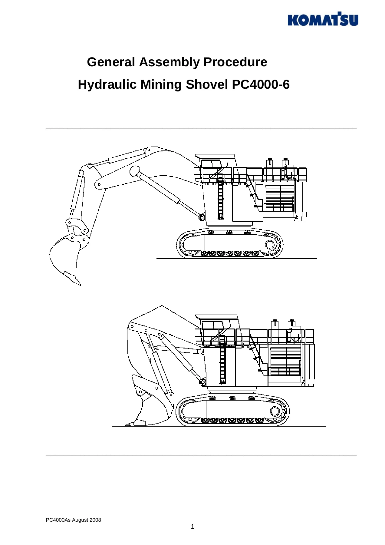
Komatsu PC4000-6 Hydraulic Mining Shovel General Assembly Procedure Manual 2008 – PDF Download
Original price was: $49.95.$32.95Current price is: $32.95.
Complete 108-page General Assembly Procedure for the Komatsu PC4000-6 hydraulic mining shovel, covering undercarriage assembly, superstructure mounting, boom and stick installation, hydraulic system setup, and all torque specifications. Published August 2008.
Description
Komatsu PC4000-6 Hydraulic Mining Shovel General Assembly Procedure
This General Assembly Procedure for the Komatsu PC4000-6 hydraulic mining shovel is the document Komatsu Mining Germany produced for field assembly of the machine. Published in August 2008 under reference PC4000As August 2008, it walks service engineers and assembly crews through every stage of putting a PC4000-6 together — from aligning the first crawler side frame to the car body, through to bleeding the work equipment circuits and completing pre-start-up checks. The manual runs 108 pages and covers both the Front Shovel and Backhoe configurations.
File Details
- Manual Type: General Assembly Procedure
- Brand: Komatsu
- Model: PC4000-6
- Language: English
- Page Count: 108
- File Format: PDF
- Date: August 2008
- Document Reference: PC4000As August 2008
Chapters Covered
The PC4000-6 assembly manual is divided into four main sections:
- 1. Overview
- 2. General
- 3. Assembly Sequence
- 4. Operation Manual: Hydraulic Torque Wrench “Avanti”
1. Overview
The opening chapter provides two illustrated component overviews. The first covers the superstructure (drawing Z22586) and identifies twenty major items including the operator’s cab with Falling Object Protective Structure (FOPS), battery main switches, engine air cleaner, cab support with electric control system, swing circle, fuel tank, hydraulically operated access ladder, counterweight, hydraulic oil cooler, hydraulic oil reservoir, power take-off with hydraulic pumps, flexible coupling, diesel engine, batteries, radiator, control valves with high-pressure in-line filters, swing machinery, central lubrication system, swing circle pinion lubrication system, and emergency escape ladder. The second overview covers the engine house (drawing Z21446) and identifies fifteen items including exhaust mufflers, engine air cleaner, expansion tank for radiator, central control and filter carrier, power take-off, main hydraulic pumps, auxiliary piggyback hydraulic pumps, hydraulic pump for radiator fan drive, hydraulic pump for hydraulic oil cooler fan drive, suction oil reservoir, flexible coupling, batteries, diesel engine, hydraulic motor for radiator fan drive, and coolant radiator with fuel cooler section.
2. General
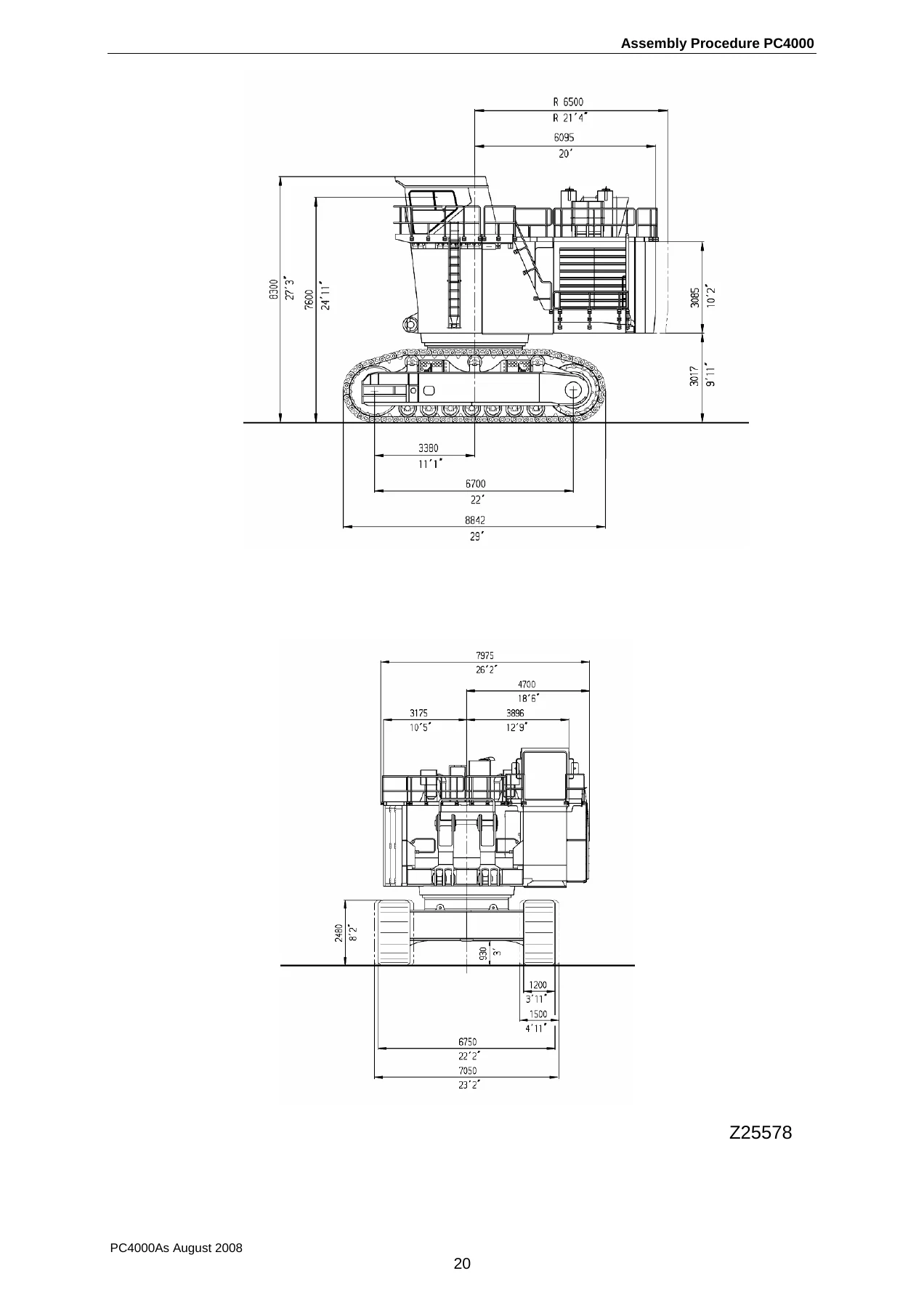
This chapter establishes the groundwork for the entire assembly operation. It covers delivery of the excavator in its disassembled main components, general assembling instructions with safety warnings, transportation and lifting procedures, a manpower and assembly time schedule, assembly site requirements (well-levelled and compacted ground of approximately 150 × 150 ft / 50 × 50 m), space and placing requirements, preparation for assembly, basic measurements with a dimensioned drawing (Z25578), transport dimensions and weights with component tables for both Front Shovel and Backhoe configurations, and a general installation procedure for hydraulic hose lines with illustrated correct and incorrect practices.
3. Assembly Sequence
The core of the PC4000-6 assembly procedure. This chapter provides step-by-step instructions with torque values, tool references, and procedural notes for every stage of assembly:
- Undercarriage assembly — including alignment of side frames, installation of M48 bolts torqued to 2100 Nm, determination of tightening torque using measuring bolts and a dial gauge, torque inspection after 1000 operating hours, final works, mounting of travel gear breather filters, and the track tensioning system.
- Superstructure assembly onto the undercarriage — including slew ring preparation, bolt greasing, installation of threaded pins for alignment, and crosswise bolt tightening.
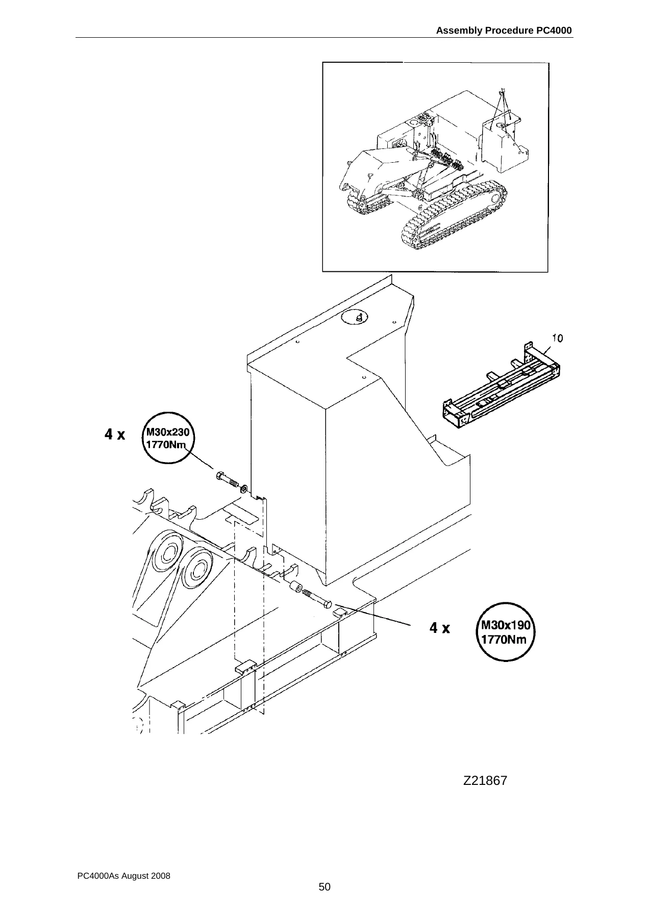
- Engine house mounting — with specific bolt sizes (8 bolts M30 × 420 and 18 bolts M30 × 440, both torqued to 1770 Nm).
- Boom mounting — including cylinder attachment, pin installation with retainers, and hydraulic connection notes.
- Hydraulic oil tank, hydraulic oil cooler, and fuel tank — with mounting procedures, bolt torques, and connection details.
- Hydraulic access ladder, cab base, and counterweight — including the counterweight’s M36 × 240 bolts at 3100 Nm and the cab base’s M42 × 520 bolts at 4950 Nm.
- Handrails, steps, and gratings — with a tightening torque table covering M4 to M12 bolts.
- Cable transfer, cab mounting with support frame, and cab air cleaner — including sealing compound application and electrical connection procedures.
- Bucket cylinders, hydraulic oil filling, and pump bleeding — with detailed bleeding sequences to prevent cavitation damage.
- Pre-checks for initial start-up — a comprehensive checklist covering fluid levels, hose connections, battery activation, engine start-up, and system bleeding.
- Stick mounting — covering both the Bullclam bucket and Backhoe attachment configurations, with pit preparation and alignment procedures.
- Stick cylinders and bucket assembly — with pin installation and locking procedures.
- Pin seals — covering both inner and outer bushing seal mounting for Bullclam and Backhoe.
- Cable harness connection to switch box “X2” — with a full terminal listing and cable marking system explanation.
- Central lubrication system commissioning — with manual pre-lubrication requirements.
- Bleeding air from work equipment circuits — with step-by-step cylinder operation sequences.
- Standard application torque tables — covering metric standard thread and metric fine thread, with values for bolt sizes from M8 through M68.
4. Operation Manual: Hydraulic Torque Wrench “Avanti”
Operating instructions for the Avanti hydraulic torque wrench, the tool specified for the high-torque bolted connections throughout the assembly procedure. Also includes a hydraulic flange assembly torque reference table with examples for SAE flange tube and hose connections (M12, M14, M16, M20).
What This Manual Enables You to Do
Assembling a Komatsu PC4000-6 hydraulic mining shovel is not a job for guesswork. With a machine this size — the superstructure platform alone weighs 57.5 tonnes, the counterweight 37 tonnes, and each crawler side frame 60 tonnes — every bolt, pin, and hose connection must be installed to exact specifications. This General Assembly Procedure gives you the manufacturer’s own step-by-step method for doing it right.
The manual is particularly valuable for:
- Assembly supervisors and field service engineers tasked with putting a PC4000-6 together at a mine site, who need the correct sequence, torque values, and safety notes in one document.
- Maintenance planners who need to understand how components are mounted so they can plan disassembly for major repairs.
- Technical trainers developing assembly training material for Komatsu mining shovel service teams.
- Mining companies taking delivery of a PC4000-6 and wanting their own engineering staff to understand the assembly process.
What sets this document apart is its specificity. It doesn’t just say “tighten the bolts” — it tells you that the M48 undercarriage bolts must be lubricated with International Compound No. 2 (PN 324 969 40), tightened to 2100 Nm, and then re-checked after 1000 operating hours using four measuring bolts and a dial gauge to determine the correct hydraulic pressure. It tells you that when mounting the boom, you should lift the front part higher than the back part to make the job easier. It tells you that the engine house bolts must be tightened immediately because later access may be difficult. These are the practical details that come from real assembly experience.
The hydraulic hose installation section is a good example of the manual’s hands-on approach. It illustrates common mistakes — twisting the hose during installation, ignoring the natural curvature, mounting 90° fittings in the wrong order, and failing to account for length changes under pressure — and shows the correct method for each. For anyone who has ever had a hydraulic hose fail prematurely because of a poor installation, this section alone justifies having the manual on hand.
Get the Komatsu PC4000-6 General Assembly Procedure PDF
IMAGES PREVIEW
This is a complete, 108-page PDF document that you can download instantly after purchase. There’s no shipping, no waiting for a physical book, and no risk of a damaged or incomplete copy. The file works on any device — laptop, tablet, or smartphone — and you can print the pages you need for the workshop or assembly site.
Whether you’re assembling a PC4000-6 from scratch, planning a major component replacement, or training a service team on Komatsu mining shovel assembly procedures, this manual gives you the manufacturer’s own instructions for doing the job correctly. The correct torque values, the right bolt sizes, the proper assembly sequence, and the safety precautions are all here — extracted directly from the August 2008 edition of Komatsu Mining Germany’s General Assembly Procedure for the PC4000-6.
Download your copy now and have the complete assembly procedure on your device in minutes.

Reviews
There are no reviews yet.