Description
Liebherr R 9600 Hydraulic Excavator Maintenance Manual – Document 12267672
Issued by Liebherr-Mining Equipment Colmar SAS under document number 12267672, this is the complete maintenance manual for the Liebherr R 9600 hydraulic excavator from serial number 47001. The manual runs to 560 pages and is the reference maintenance personnel are required to read and fully understand before any work is performed on the machine. It belongs to the excavator for its entire service life and covers every scheduled inspection, fluid change, filter replacement, adjustment and safety check the R 9600 needs across daily, 250-hour, 500-hour, 1000-hour and 2000-hour maintenance intervals.
The R 9600 is a 600-tonne-class mining excavator built around a Cummins QSK50 twin-engine powerpack, a closed-loop swing circuit with kinetic energy recovery, four independent hydraulic oil coolers and a fully automated SKF centralized lubrication system. Maintenance on a machine of this scale is specialised work, and the tolerances, torque values and fluid specifications are precise. This Liebherr R 9600 maintenance manual provides those values and the procedures that go with them, so a mine maintenance team can keep the excavator safe, reliable and productive over its working life.
What the R 9600 Maintenance Manual Covers
The manual is organised into six top-level chapters that mirror the way maintenance work is actually planned and carried out on a large mining excavator. It opens with a full product description and technical data set for the R 9600 in both backhoe and shovel attachment configurations, then moves through the safety framework that governs every task, the special tools and tightening standards that must be used, the fault-finding and error-code section, the complete maintenance chapter broken down system by system, and an appendix covering the centralized lubrication system, the pneumatic system and conversion factors.
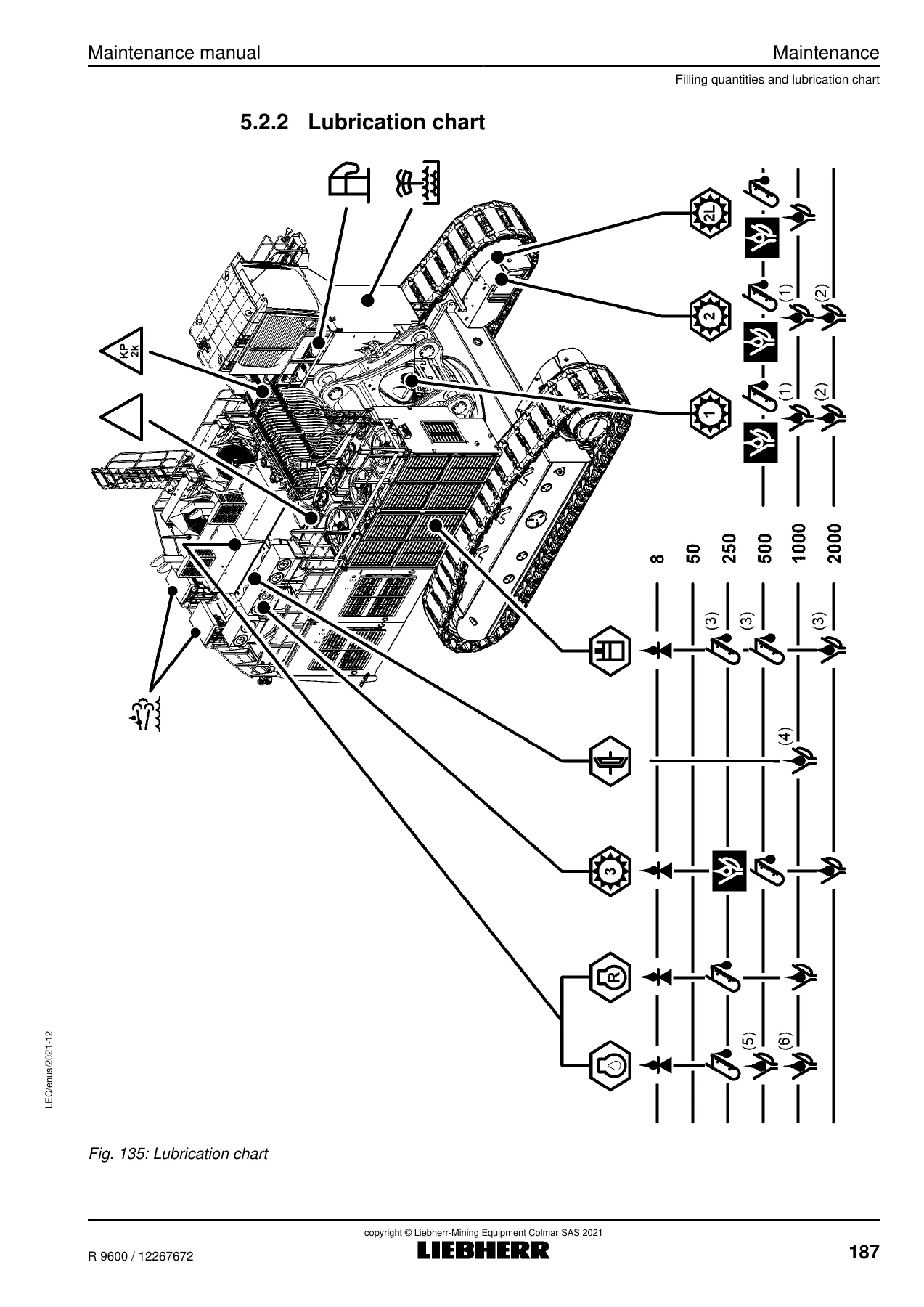
Because maintenance on the R 9600 is scheduled rather than reactive, the inspection and maintenance chart is the operational backbone of the document. It splits every task into daily, 250-hour, 500-hour, 1000-hour and 2000-hour schedules, marks who is authorised to carry out each task, and gives the procedure code and page reference so the technician can move directly to the instruction. Fill quantities, lubrication charts, fluid and lubricant specifications and oil-analysis action levels support the schedule so a maintenance planner can order the right consumables and set sampling intervals with confidence.
On the procedure side, the R 9600 maintenance manual goes into the machine system by system. It covers the track components and track tensioning circuit, the travel gear and its Lifetime interspace, the swing gear and swing ring, the hydraulic rotary connection, both Cummins QSK50 diesel engines and the splitterbox and coupling, the Oil Reserve System (ORS), the cooling system and Selective Catalytic Reduction (SCR) system with Diesel Exhaust Fluid handling, the fuel and air intake systems, the entire hydraulic system including the working pumps, swing pumps, servo oil circuits and high-pressure filters, the electrical system and batteries, the pneumatic system, the cab, and the heating and air-conditioning system. Transportation and emergency operation procedures close the main chapter.
File Details
- Manual type: Maintenance manual
- Brand / manufacturer: Liebherr-Mining Equipment Colmar SAS
- Model: R 9600 hydraulic excavator
- Document / order number: 12267672
- Issued: 2021-12
- Author: LEC / Technical Documentation Department
- Type no.: 1391 / 1679
- Applies from serial number: 47001
- Language: English
- Page count: 560
- File format: PDF
Chapters Covered
- 1 Product description – machine overview, uppercarriage, undercarriage, identification plate, operating technical data, specifications
- 2 Safety – information in this manual, intended application, personnel requirements, identification of hazards, general safety instructions, operation safety, maintenance safety, signs on the machine, protective equipment, emergency equipment, modifications
- 3 Tools and standards – special tools, tightening standards, tightening of screws, tightening of hydraulic flanges, tightening of VSTI plugs, dimensions of tightening tools, hoses service life
- 4 Malfunctions – error codes, fault-cause-remedy, fuses and relays for the elevation electrical cabinet, cab electrical cabinet, SCR electrical box and customer electrical cabinet
- 5 Maintenance – inspection and maintenance chart, filling quantities and lubrication chart, fuel, lubricants and operation fluids, condition monitoring with oil analysis, service trap, access and anchor points, general fastening, track components, travel gear, hydraulic rotary connection, swing gear, diesel engine, Oil Reserve System, splitterbox, coupling, cooling system, fuel system, SCR system, air intake system, hydraulic system, electrical system, pneumatic system, cab, heating and air-conditioning system, windshield washer, transportation, emergency operation
- 6 Appendix – centralized lubrication system, pneumatic system, list of acronyms, conversion factors
Read together, the chapters take a maintenance technician from understanding what the R 9600 is and how it is laid out, through the safety rules that apply before any tool is picked up, to the actual torque values, fluid quantities, service limits and step-by-step procedures needed to complete a service correctly. The depth is unusual even for a large mining manual: the R 9600 maintenance manual does not just tell you to change a filter, it gives you the correct procedure, the correct torque, the correct O-ring and the next step in the chain so nothing is left to guesswork.
Machine Data Highlights
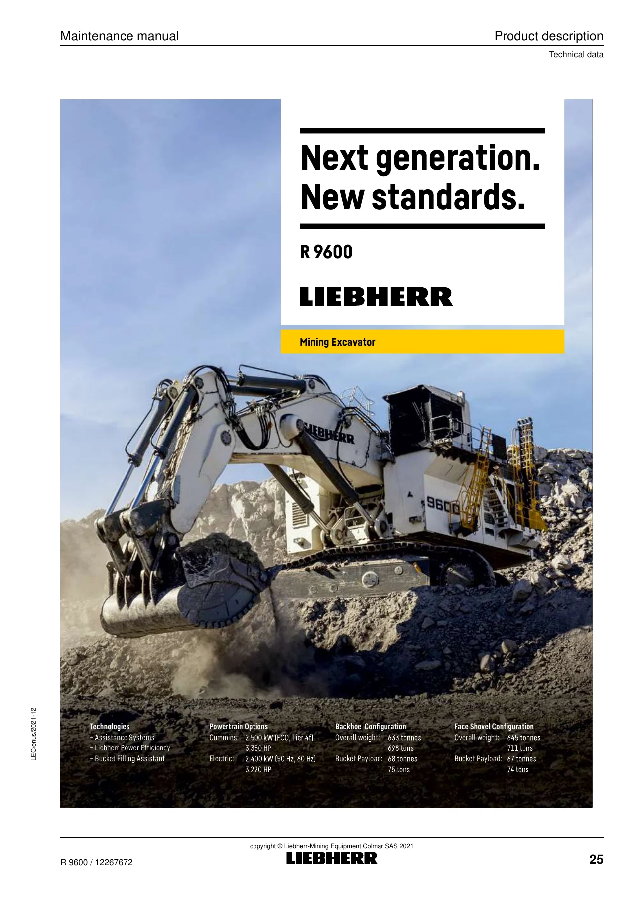
Technical data drawn from the manual shows the R 9600 with either a backhoe attachment (maximum working slope 3 degrees or 5 percent with the 37.5 m3 bucket) or a shovel attachment (4 degrees or 7 percent with the 37 m3 bucket), a maximum travelling angle of 17 degrees, and an operating ambient temperature range of -10 to +55 degrees Celsius. The powertrain is listed as two Cummins QSK50 engines rated at 2 x 1,250 kW / 2 x 1,675 HP at 1,800 rpm, with an electric drive option rated at 2 x 1,200 kW. Fuel capacity is 14,067 litres, Diesel Exhaust Fluid capacity is 2 x 564 litres, and the hydraulic system holds up to 9,800 litres across the tank and full circuit. Backhoe operating weight is 633 tonnes and face shovel operating weight is 645 tonnes, with corresponding bucket capacities of 37.5 m3 and 37.0 m3.
Why This Manual Matters for R 9600 Maintenance
A Liebherr R 9600 is not a machine that can be maintained by feel. The hydraulic system runs at pressures up to 320 bar, the undercarriage uses hydraulically tensioned track chains, the swing ring uses a sealed triple roller bearing with internal teeth, and the electrical system uses a 24 V architecture with a large number of monitored sensors and control units. Every one of those systems has a specified service interval, a specified fluid, a specified torque and a specified condition check. Using the wrong one can shorten component life, trigger derates, or create a safety hazard.
This manual gives the numbers. It lists the tightening torque values for standard metric threads, metric fine pitch threads, UNC and UNF threads and hydraulic flanges, with separate values for dry, greased, cast iron and aluminium applications. It gives the fluid specifications for splitterbox oil, swing gear oil, travel gear oil, track roller oil, carrier roller oil, idler oil and hydraulic oil, including cold-climate options. It gives the action level values for iron, copper, silicon, water, viscosity and additives in each oil sample so the condition-monitoring programme can be run properly. And it gives the grease specifications for the centralized lubrication system, with separate requirements for the P1/P2 system and the P3 swing ring teeth system.
Also included are the special tools needed for work on the R 9600: torque wrenches, hydraulic torque wrenches, bolt tensioning cylinders with 1500 bar supply, vacuum pumps, accumulator charging kits, sampling kits, track wear measuring kits and the Lifetime interspace flushing device. Every procedure in the manual references the tool it needs, so a workshop can prepare properly before the machine is parked.
Safety and Emergency Content
The safety chapter alone is a serious reference. It covers injection and fluid ejection hazards, crushing and impact hazards, slipping, tripping and falling hazards, entanglement and drawing-in hazards, burn and scald hazards, electric shock and electrocution hazards, fire and explosion hazards, suffocation, irritation and poisoning hazards and vibration hazards. It then sets out specific safety instructions for accessing the machine, the operator cab, the operator seat, the seat belt, starting, parking, stopping, exiting, fire, weather conditions and working near overhead and underground infrastructure. Safety instructions for maintenance cover fuel, lubricants, operating fluids and consumables, refuelling, cleaning, the electrical system, the hydraulic system, corrosion protection, crack testing, welding, drilling, firing and grinding, and the attachment.
Complete PDF Bookmark Tree
Complete Bookmarks
The complete bookmarks in the “Liebherr R 9600 Hydraulic Excavator Maintenance Manual 2021 – PDF Download” are as follows:
+Maintenance manualp. 1
Prefacep. 3
Contentsp. 7
+1 Product descriptionp. 19
+1.1 Overviewp. 19
1.1.1 Machinep. 19
1.1.2 Uppercarriagep. 21
1.1.3 Undercarriagep. 22
1.1.4 Identification platep. 22
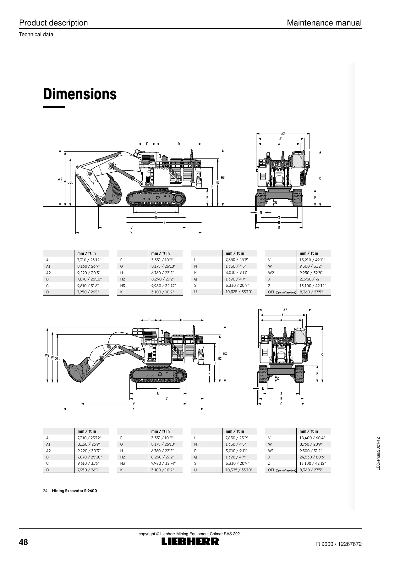
+1.2 Technical datap. 24
1.2.1 Operating technical datap. 24
1.2.2 Specificationsp. 24
+2 Safetyp. 53
+2.1 Information in this manualp. 53
2.1.1 Presentation of safety messagesp. 53
2.1.2 Graphical symbols in this manualp. 54
+2.2 Intended applicationp. 56
2.2.1 Laws, rules, guidelines and safety instructionsp. 56
2.2.2 Intended usep. 56
2.2.3 Foreseeable misusep. 57
2.2.4 Operating conditionsp. 58
2.2.5 Disposalp. 58
+2.3 Personnel requirementsp. 60
2.3.1 Personal Protective Equipment (PPE)p. 60
2.3.2 Personnel qualificationsp. 60
+2.4 Identification of hazardsp. 62
2.4.1 Injection and fluid ejection hazardsp. 62
2.4.2 Crushing and impact hazardsp. 62
2.4.3 Slipping, tripping and falling hazardsp. 63
2.4.4 Entanglement, drawing-in, cutting and severing hazardsp. 63
2.4.5 Burn and scald hazardsp. 63
2.4.6 Electric shock and electrocution hazardsp. 64
2.4.7 Fire and explosion hazardsp. 65
2.4.8 Suffocation, irritation and poisoning hazardsp. 66
2.4.9 Vibration hazardsp. 66
+2.5 Safety instructions for general purposesp. 67
2.5.1 Safety instructions when accessing the machinep. 67
2.5.2 Safety instructions for the operator cabp. 67
2.5.3 Safety instructions for the operator seatp. 67
2.5.4 Safety instructions for the seat beltp. 68
2.5.5 Safety instructions when starting the machinep. 68
2.5.6 Safety instructions when parking the machinep. 68
2.5.7 Safety instructions when stopping the machinep. 69
2.5.8 Safety instructions when exiting the machinep. 69
2.5.9 Safety instructions in case of firep. 69
2.5.10 Safety instructions related to weather conditionsp. 70
2.5.11 Safety instructions when using the machine near overhead and underground infrastructuresp. 70
+2.6 Safety instructions for operationp. 72
2.6.1 Safety instructions for the walk-around inspectionp. 72
2.6.2 Safety instructions before setting the machine into operationp. 72
2.6.3 Safety instructions when working with the machinep. 73
2.6.4 Safety instructions for transportationp. 74
2.6.5 Safety instructions for lifting and tie-down operationsp. 74
+2.7 Safety instructions for maintenancep. 77
2.7.1 General safety instructions for maintenancep. 77
2.7.2 Safety instructions for fuel, lubricants, operating fluids and consumablesp. 78
2.7.3 Safety instructions when refuelingp. 78
2.7.4 Safety instructions when cleaning the machinep. 79
2.7.5 Safety instructions for the maintenance of the electrical systemp. 80
2.7.6 Safety instructions for the maintenance of the hydraulic systemp. 80
2.7.7 Safety instructions for corrosion protectionp. 82
2.7.8 Safety instructions for crack testingp. 82
2.7.9 Safety instructions for welding, drilling, firing and grinding workp. 82
2.7.10 Safety instructions for the maintenance of the attachmentp. 83
+2.8 Signs on the machinep. 84
2.8.1 Types of signsp. 84
2.8.2 Signs on the uppercarriagep. 85
2.8.3 Signs in the powerpackp. 90
2.8.4 Signs in the cabp. 92
+2.9 Protective equipment on the machinep. 94
2.9.1 Safety leverp. 94
2.9.2 Falling Object Protective Structures (FOPS) and Front Guard Protective Structures (FGPS)p. 94
+2.10 Emergency equipment on the machinep. 95
2.10.1 Emergency stopp. 95
2.10.2 Emergency exitp. 95
2.10.3 Fire extinguisher (optional equipment)p. 95
2.10.4 Fire suppression system (optional equipment)p. 95
2.11 Modifications to the machinep. 96
+3 Tools and standardsp. 97
3.1 Special toolsp. 97
+3.2 Tightening standardsp. 107
3.2.1 Tightening of screwsp. 107
3.2.2 Tightening of hydraulic flangesp. 113
3.2.3 Tightening of VSTI plugsp. 116
3.2.4 Dimensions of the tightening toolsp. 116
+3.3 Hoses service lifep. 118
3.3.1 Natural ageing of hose assembliesp. 118
3.3.2 Operating stressp. 119
+4 Malfunctionsp. 121
+4.1 Error codesp. 121
4.1.1 Centralized lubrication systemp. 121
4.2 Fault – Cause – Remedyp. 123
+4.3 Fuses and relaysp. 124
4.3.1 Elevation electrical cabinet U1003p. 124
4.3.2 Cab electrical cabinet U1005p. 132
4.3.3 Electrical box for the Selective Catalytic Reduction (SCR) system U1091p. 137
4.3.4 Customer electrical cabinet U1015p. 138
+5 Maintenancep. 141
+5.1 Inspection and maintenance chartp. 141
5.1.1 General informationp. 141
5.1.2 Maintenance levelsp. 141
5.1.3 Inspection typesp. 142
5.1.4 How to use the inspection and maintenance chartp. 142
5.1.5 Daily inspection and maintenance schedule – R 9600p. 144
5.1.6 250 hours inspection and maintenance schedule – R 9600p. 151
5.1.7 500 hours inspection and maintenance schedule – R 9600p. 158
5.1.8 1000 hours inspection and maintenance schedule – R 9600p. 166
5.1.9 2000 hours inspection and maintenance schedule – R 9600p. 175
+5.2 Filling quantities and lubrication chartp. 185
5.2.1 Filling quantitiesp. 185
5.2.2 Lubrication chartp. 187
+5.3 Fuel, lubricants and operation fluidsp. 190
5.3.1 General informationp. 190
5.3.2 Lubricants and operation fluids specificationp. 190
5.3.3 Diesel fuelp. 198
5.3.4 Diesel Exhaust Fluid (DEF)p. 198
5.3.5 Lubricating oil for the Diesel enginep. 198
5.3.6 Coolantp. 198
5.3.7 Splitterbox oilp. 199
5.3.8 Coupling oilp. 199
5.3.9 Hydraulic oilp. 199
5.3.10 Swing gear oilp. 203
5.3.11 Travel gear oilp. 204
5.3.12 Oil for the Lifetime interspacep. 204
5.3.13 Travel brake oilp. 204
5.3.14 Track roller oilp. 204
5.3.15 Carrier roller oilp. 204
5.3.16 Idler oilp. 204
5.3.17 Grease for the centralized lubrication systemp. 205
5.3.18 Grease for the hydraulic rotary connectionp. 205
5.3.19 Windshield washer fluidp. 205
5.3.20 Refrigerant and oil for the air-conditioning systemp. 205
5.3.21 Lubricants and care products for electrical and mechanical systemsp. 206
+5.4 Condition monitoring with oil analysisp. 207
5.4.1 General informationp. 207
5.4.2 Oil samplingp. 207
5.4.3 Sample processingp. 213
+5.5 Service trapp. 217
5.5.1 Overviewp. 217
5.5.2 Operate the service trapp. 218
+5.6 Access points for the maintenancep. 221
5.6.1 General access pointsp. 221
5.6.2 Foldable platform (optional equipment)p. 222
+5.7 Anchor points for the maintenancep. 225
5.7.1 Approved anchor pointsp. 225
5.7.2 Use the anchor pointsp. 228
+5.8 General instructions for maintenancep. 229
5.8.1 Prepare the machine for the maintenancep. 229
5.8.2 Machine position for the maintenancep. 229
+5.9 General fasteningp. 231
5.9.1 General informationp. 231
5.9.2 Counterweight fasteningp. 232
5.9.3 Swing ring fasteningp. 234
5.9.4 Swing gear fasteningp. 236
5.9.5 Fuel tank fasteningp. 238
5.9.6 Hydraulic tank fasteningp. 239
5.9.7 Cab fasteningp. 241
5.9.8 Powerpack fasteningp. 242
5.9.9 Diesel engine fasteningp. 244
5.9.10 Splitterbox fasteningp. 245
5.9.11 Hydraulic pumps fasteningp. 247
5.9.12 Side frame fasteningp. 248
5.9.13 Track components fasteningp. 250
+5.10 Track componentsp. 257
5.10.1 Track components: clean the track componentsp. 257
5.10.2 Track components: check the track tensionp. 257
5.10.3 Track components: release the track tensionp. 259
5.10.4 Track components: put the track chain under tensionp. 260
+5.11 Travel gearp. 262
5.11.1 Travel gear: check the oil levelp. 262
5.11.2 Travel gear: change the oilp. 263
5.11.3 Travel gear: change the Lifetime interspace oilp. 265
5.11.4 Travel gear: change the travel brake oilp. 268
+5.12 Hydraulic rotary connectionp. 270
5.12.1 Hydraulic rotary connection: grease the hydraulic rotary connectionp. 270
5.12.2 Hydraulic rotary connection: replace the filterp. 271
+5.13 Swing gearp. 272
5.13.1 Swing gear: check the oil levelp. 272
5.13.2 Swing gear: change the oilp. 273
5.13.3 Swing gear: check the axial play of the output shaft bearingp. 276
+5.14 Diesel enginep. 277
5.14.1 Diesel engine: check the oil levelp. 277
5.14.2 Diesel engine: check the mountsp. 279
5.14.3 Diesel engine: change the oilp. 280
5.14.4 Diesel engine: replace the oil filterp. 283
+5.15 Oil Reserve System (ORS) (optional equipment)p. 285
5.15.1 Oil Reserve System (ORS): check the oil levelp. 285
5.15.2 Oil Reserve System (ORS): check the system for correct operationp. 287
5.15.3 Oil Reserve System (ORS): change the oilp. 288
5.15.4 Oil Reserve System (ORS): replace the oil filterp. 291
5.15.5 Oil Reserve System (ORS): replace the centrifuge rotorp. 292
+5.16 Splitterboxp. 294
5.16.1 Splitterbox: check the oil levelp. 294
5.16.2 Splitterbox: check the mountsp. 295
5.16.3 Splitterbox: change the oilp. 296
5.16.4 Splitterbox: replace the filter element of the oil filterp. 299
5.16.5 Splitterbox: replace the filter element of the breatherp. 301
+5.17 Couplingp. 302
5.17.1 Coupling: check the wearp. 302
5.17.2 Coupling: change the oil (only for the oil-filled coupling)p. 304
+5.18 Cooling systemp. 306
5.18.1 Cooling system: check the coolant levelp. 306
5.18.2 Cooling system: change the coolantp. 307
5.18.3 Cooling system: replace the coolant filterp. 317
5.18.4 Cooling system: check the system for correct conditionp. 318
+5.19 Fuel systemp. 319
5.19.1 Fuel system: check the fuel levelp. 319
5.19.2 Fuel system: refuelp. 319
5.19.3 Fuel system: drain the fuel tankp. 320
5.19.4 Fuel system: replace the filter element of the fuel tank breatherp. 322
5.19.5 Fuel system: drain the water separatorp. 323
5.19.6 Fuel system: check the filter replacement indicatorp. 324
5.19.7 Fuel system: replace the preliminary fuel filterp. 325
5.19.8 Fuel system: replace the fuel filterp. 327
5.19.9 Fuel system: bleed the fuel systemp. 328
+5.20 Selective Catalytic Reduction (SCR) systemp. 330
5.20.1 Selective Catalytic Reduction (SCR) system: check the level of Diesel Exhaust Fluid (DEF)p. 330
5.20.2 Selective Catalytic Reduction (SCR) system: fill with Diesel Exhaust Fluid (DEF)p. 330
5.20.3 Selective Catalytic Reduction (SCR) system: drain the Diesel Exhaust Fluid (DEF)p. 334
5.20.4 Selective Catalytic Reduction (SCR) system: replace the filter element of the Diesel Exhaust Fluid (DEF) filterp. 336
+5.21 Air intake systemp. 338
5.21.1 Air intake system: check the filter replacement indicatorp. 338
5.21.2 Air intake system: replace the primary element of the air intake filterp. 339
5.21.3 Air intake system: replace the safety element of the air intake filterp. 340
5.21.4 Air intake system: clean the precleanerp. 342
5.21.5 Air intake system: check the air intake hose for correct conditionp. 343
+5.22 Hydraulic systemp. 345
5.22.1 Hydraulic system: check the position of the hydraulic shutoff valvep. 345
5.22.2 Hydraulic system: release the pressure from the hydraulic systemp. 345
5.22.3 Hydraulic system: drain water from the hydraulic tankp. 353
5.22.4 Hydraulic system: check the oil levelp. 354
5.22.5 Hydraulic system: change the hydraulic oilp. 356
5.22.6 Hydraulic system: replace the filter element of the leak oil filterp. 359
5.22.7 Hydraulic system: replace the filter element of the return filterp. 361
5.22.8 Hydraulic system: replace the filter element of the bypass filter (optional equipment)p. 363
5.22.9 Hydraulic system: replace the air filter for the hydraulic tankp. 365
5.22.10 Hydraulic system: replace the filter element of the servo oil filterp. 366
5.22.11 Hydraulic system: replace the filter element of the replenishing filter for the swing pumpp. 367
5.22.12 Hydraulic system: replace the high-pressure filterp. 368
5.22.13 Hydraulic system: replace the protective filter for the oil cooler (optional equipment)p. 370
5.22.14 Hydraulic system: check the condition of the hydraulic cylinder rodp. 371
5.22.15 Hydraulic system: bleed the valve blocksp. 372
5.22.16 Hydraulic system: bleed the hydraulic pumpsp. 372
5.22.17 Hydraulic system: bleed the hydraulic cylinderp. 374
5.22.18 Hydraulic system: prevent corrosion on the hydraulic cylinderp. 374
5.22.19 Hydraulic system: replace the intake lines for the hydraulic pumpsp. 376
5.22.20 Hydraulic system: replace the hydraulic hosesp. 379
5.22.21 Hydraulic system: check the hydraulic hoses visuallyp. 381
5.22.22 Hydraulic system: clean the hydraulic circuitsp. 390
+5.23 Electrical systemp. 442
5.23.1 Electrical system: check the battery electrolyte levelp. 442
5.23.2 Electrical system: clean the battery terminalsp. 444
+5.24 Pneumatic systemp. 446
5.24.1 Pneumatic system: check the system for correct operationp. 446
5.24.2 Pneumatic system: release the pressure from the systemp. 447
+5.25 Cabp. 448
5.25.1 Cab: check the mountsp. 448
+5.26 Heating and air-conditioning systemp. 449
5.26.1 Possible configurationsp. 449
5.26.2 Heating and air-conditioning system: check the condenser unitp. 452
5.26.3 Heating and air-conditioning system: check the evaporatorp. 453
5.26.4 Heating and air-conditioning system: replace the evaporator filterp. 454
5.26.5 Heating and air-conditioning system: check the refrigerant levelp. 455
5.26.6 Heating and air-conditioning system: replace the filter-drierp. 456
5.26.7 Heating and air-conditioning system: replace the refrigerant receiverp. 457
5.26.8 Heating and air-conditioning system: check the heaterp. 458
5.26.9 Heating and air-conditioning system: replace the heater filterp. 459
5.26.10 Heating and air-conditioning system: bleed the heaterp. 460
5.26.11 Heating and air-conditioning system: clean the air cleanerp. 461
5.26.12 Heating and air-conditioning system: replace the primary element of the air cleanerp. 462
5.26.13 Heating and air-conditioning system: replace the safety element of the air cleanerp. 463
+5.27 Windshield washerp. 465
5.27.1 Windshield washer: check the level of windshield washer fluidp. 465
5.27.2 Windshield washer: fill with windshield washer fluidp. 466
+5.28 Transportationp. 468
5.28.1 Lift and tie-downp. 468
5.28.2 Transport plansp. 468
+5.29 Emergency operationp. 482
5.29.1 Jump-startp. 482
5.29.2 Tow the machinep. 483
+6 Appendixp. 485
6.1 Centralized lubrication systemp. 485
6.2 Pneumatic systemp. 537
6.3 List of acronymsp. 558
6.4 Conversion factorsp. 559
The emergency operation section covers jump-starting the R 9600 with jump-start cables or the auxiliary start receptacles X60_1, X60_2 and X60_3, and states plainly that towing the machine is not permitted – the Customer Service must be contacted for recovery of a defective or unserviceable machine.
Get the Liebherr R 9600 Maintenance Manual Today
This Liebherr R 9600 hydraulic excavator maintenance manual is delivered as an instant PDF download after payment. There is no shipping, no waiting for a physical book, and no risk of a damaged or missing copy. The file opens on any modern device – desktop, laptop, tablet or phone – and every page can be printed for workshop use, which is exactly how a maintenance manual for a 600-tonne mining excavator is meant to be used.
Whether you run a single R 9600 or a fleet of them, whether you are building a maintenance plan, training a technician, preparing for a 2000-hour service, or verifying that a machine has been correctly looked after, the R 9600 maintenance manual from Liebherr-Mining Equipment Colmar SAS is the document that tells you what to do, in what order, with what values and to what tolerance. Add it to your library and have it ready the next time the excavator is due for service.




Reviews
There are no reviews yet.