Description
The P&H 320XPC Rotary Blasthole Drill Mechanical Systems Manual is the full mechanical service reference for the 320XPC rotary blasthole drill, running from daily preventive maintenance all the way through teardown and rebuild of the major assemblies. Every procedure is written around the hardware actually installed on the machine, so exploded views, sectional drawings, hydraulic schematics, pressure tap tables and torque charts sit directly alongside the steps they belong to. A technician working from this 320XPC mechanical systems manual does not have to guess at a clearance, a shim thickness or a relief valve setting.
File Details
- Manual type: Mechanical systems service, maintenance and repair manual
- Brand: P&H Mining Equipment (Joy Global Surface Mining Inc.)
- Model: 320XPC rotary blasthole drill
- Language: English
- Page count: 566 pages
- File format: PDF
- Document number: 32XC-D-M-MM-EN-0000TOC
- Publication information shown: Copyright 2014, Joy Global Surface Mining Inc.; section revisions dated 11/14, appendices dated 04/08
Chapters Covered in This P&H 320XPC Mechanical Systems Manual
- Section 1 – Blasthole Drill Safety: operator qualifications, operator conduct, functional checks, operation near electrical lines, safety decals and signs
- Section 2 – Introduction: part numbers, applicability, drill description, power unit, lower final assembly (undercarriage and propel), rotary carriage, mast, mast lock assembly and back braces, drill pipe storage and handling, auxiliary winch, deck wrenches, operator controls, hydraulic systems, water injection, automatic lubrication, bailing air system, towing system, dust curtains, serial number location, sign maintenance, MSDS
- Section 3 – Preventive Maintenance: lubrication, bolt lubrication, bolt torques, maintenance schedule check sheets, “A” through “F” maintenance checks with individual procedures
- Section 4 – Cable Reel: operation, controls, trail cable installation, periodic maintenance, lubrication, inspection, adjustments, post startup, hydraulic schematic, component repair including collector ring assembly
- Section 5 – Electrical System: refers to the separate Centurion Drill Electrical Maintenance Manual
- Section 6 – Power Unit: power unit arrangement, alignment procedures, main drive motor, air compressor, hydraulic pump drive transmission removal, disassembly, repair and installation
- Section 7 – Main Air System: major component locations, subsystems, air compressor oil circulation, scavenger oil subsystem, air intake subsystem, discharge system
- Section 8 – Water Injection System: theory of operation, water tank, submersible water pump, sensing components, troubleshooting
- Section 9 – Hydraulic System: shared components, hydraulic tank, oil cooler, thermostatic mixing valve, oil replenishment, propel hydraulic components, valve bank 4, main hydraulic pumps, towing system, auxiliary hydraulic system, valve banks 1, 2 and 3, low pressure hydraulic system
- Section 10 – Propel System: propel motor, propel transmission, crawler final assembly, crawler frames, idler roller, upper and lower rollers, crawler track assembly, track tension adjustment
- Section 11 – Leveling System: rear jacks, rear jack hydraulic cylinder repair, front jacks, leveling jack shoes, troubleshooting
- Section 12 – Lubrication: lubricant specifications, cold weather operation, viscosity, ISO grades, oil bath lubrication, oil pressure lubrication, hydraulic tank, manual lubrication points, lubrication schedule, automatic lubrication system, troubleshooting
- Section 13 – Mast: theory of operation, mast components, back braces, locking collar cylinders, mast locking assemblies, mast raise/lower cylinders, lower mast assembly, dust deflector, hinge pins, bailing air components, troubleshooting
- Section 14 – Hoist/Pulldown Machinery: pulldown motor, blower, pulldown gearcase, pulldown brake, pulldown resolver, drive and idler pinions, guide rollers, troubleshooting
- Section 15 – Rotary Machinery: rotary gearcase, drill pipe coupling, rotary motor, bit air components, oil pump and lines, intermediate drive, main drive, bearing preload check and adjustment, troubleshooting
- Section 16 – Pipe Handling Equipment: pipe racks, deck wrench, breakout wrench, inspection, adjustment, pipe rack liners, upper support arm, limit switches, troubleshooting
- Section 17 – House Pressurization: blowers, filters, filter housing removal, filter cleaning
- Section 18 – Auxiliary Winch: winch removal and installation, motor repair, brake repair, final drive repair, primary drive and drum repair, sheaves
- Section 19 – Cab Climate Control: installation, electrical module, refrigeration, heater, pressurizer, maintenance, troubleshooting
- Section 20 – Optional Equipment: auxiliary air system, boarding ladders, lubricant replenishment and top off systems, Wiggins quick fill, jib crane
- Appendix A – General Maintenance: removal, disassembly, inspection, cleaning and repair, assembly, bearings, couplings, alignment, sheaves, gears, gear tooth wear, shafts
- Appendix B – General Hydraulic System Maintenance: maintenance rules, tightening hydraulic connections, pipe thread, SAE flare, SAE straight thread, split flange and flat face O-ring connections, troubleshooting hydraulic systems
What This Manual Gives a Technician
This is a systems manual in the practical sense. Each of the drill’s mechanical systems is broken out into its own section with a theory of operation at the front, component descriptions in the middle, and removal, disassembly, cleaning, inspection, repair, assembly and installation procedures behind that. Where a procedure depends on a measurement, the measurement is given. Where it depends on a special tool, the tool is named. Where a valve or relief setting must be checked, the manual identifies the pressure tap by number and states the expected reading, so diagnostics follow a defined path rather than trial and error.
Complete PDF Bookmark Tree
Complete Bookmarks
The complete bookmarks in the “P&H 320XPC Rotary Blasthole Drill Mechanical Systems Manual PDF” are as follows:
Prefacep. 2
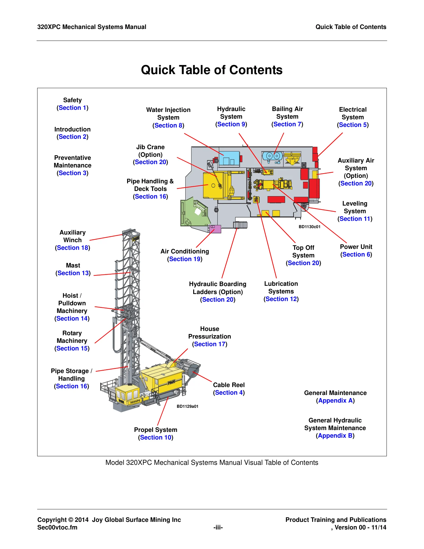
Quick Table of Contentsp. 4
Table of Contentsp. 6
List of Figuresp. 16
List of Tablesp. 24
+Blasthole Drill Safetyp. 28
1.1 Operator Qualificationsp. 28
1.2 Operator Conductp. 28
1.3 Functional Checksp. 29
1.4 Operation Near Electrical Lines Precautionsp. 29
+1.5 Safety Decals and Signsp. 30
1.5.1 Generalp. 30
1.5.2 Hazard Indicatorsp. 30
1.5.3 Safety Hazard Decals and Signsp. 31
+Introductionp. 32
+2.1 Generalp. 32
2.1.1 Part Numbersp. 32
2.1.2 Applicabilityp. 32
+2.2 Descriptionp. 32
2.2.1 Generalp. 32
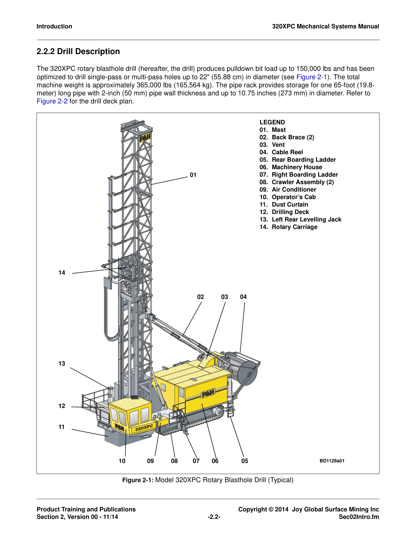
2.2.2 Drill Descriptionp. 33
2.2.3 Power Unitp. 34
2.2.4 Lower Final Assembly (Undercarriage and Propel)p. 35
2.2.5 Rotary Carriagep. 35
2.2.6 Mast, Mast Lock Assy, and Back Bracesp. 35
2.2.7 Drill Pipe Storage and Handlingp. 36
2.2.8 Auxiliary Winchp. 36
2.2.9 Deck Wrenchesp. 36
2.2.10 Operator’s Controlsp. 37
+2.2.11 Hydraulic Systemsp. 37
2.2.11.1 Propel (Main) Hydraulic Systemp. 37
2.2.11.2 Auxiliary and Low Pressure Hydraulic Systemp. 37
2.2.12 Water Injection Systemp. 37
2.2.13 Automatic Lubrication Systemp. 37
2.2.14 Bailing (Main) Air Systemp. 38
2.2.15 Towing Systemp. 38
2.2.16 Dust Curtainsp. 38
2.3 Serial Number Locationp. 38
2.4 Sign Maintenancep. 38
2.5 Material Safety Data Sheets (MSDS)p. 39
+Preventive Maintenancep. 40
3.1 Generalp. 40
3.2 Lubricationp. 40
3.3 Bolt Lubricationp. 40
+3.4 Bolts And Bolt Torquesp. 40
3.4.1 Special Bolt Tightening Requirementsp. 43
+3.5 Maintenance Schedule Check Sheetsp. 45
3.5.1 Generalp. 45
3.5.2 Using The Maintenance Schedule Check Sheetsp. 45
3.6 Maintenance Schedule Tablesp. 46
+3.7 “A” Maintenance Checks (Daily or 8-10 Hours)p. 52
3.7.1 Note and Record Any Faults Displayed on GUI Fault Logp. 52
3.7.2 lnspect Operator Cab Air Filtersp. 53
3.7.3 Check Hydraulic Tank Oil Levelp. 54
+3.7.4 Check Hydraulic Tank Breather Condition Indicatorp. 55
3.7.4.1 Generalp. 55
3.7.4.2 Servicep. 55
3.7.4.3 Replacementp. 55
3.7.5 Check Pump Drive Transmission Oil Levelp. 55
3.7.6 Check Main Air Compressor Oil Reservoir Levelp. 57
3.7.7 Fill Water Tankp. 58
3.7.8 lnspect Deck Wrenchesp. 58
3.7.9 lnspect Auxiliary Winch and Wire Ropep. 59
3.7.10 lnspect Drill Pipe Slingsp. 59
3.7.11 Inspect Pipe Rack Operationp. 59
3.7.12 Check Rotary Gearcase Oil Levelp. 59
3.7.13 Check Pulldown Gearcase Oil Levelp. 61
+3.7.14 Inspect Rotary Carriage Rollersp. 62
3.7.14.1 Carriage Roller Adjustmentp. 63
+3.7.15 Inspect Machine For Damage And Leaksp. 63
3.7.15.1 lnspect Air Lines For Leaksp. 64
3.7.15.2 lnspect Hoses And Hydraulic Linesp. 64
3.7.15.3 lnspect Hydraulic Fittings For Leaksp. 64
3.7.15.4 lnspect Dust Curtainp. 64
3.7.16 Inspect Crawlersp. 64
3.7.17 lnspect Jack Shoes And Retaining Pinsp. 64
3.7.18 lnspect Jack Housing and Cylinder Mounting Hardwarep. 64
3.7.19 Inspect Auxiliary Air Compressor Before Usingp. 64
+3.8 “B” Maintenance Checksp. 65
3.8.1 Perform “A” Maintenance Checksp. 65
3.8.2 lnspect Hydraulic System Componentsp. 65
3.8.3 lnspect Breakout Wrenchp. 65
3.8.4 Inspect Pipe Rack Conditionp. 65
3.8.5 lnspect Mast Racks and Pinionsp. 66
3.8.6 lnspect Rotary Machineryp. 66
3.8.7 Inspect Bailing Air System Componentsp. 67
3.8.8 Check Main Compressor Oil Separator Filtersp. 68
3.8.9 Check Main Compressor Air Intake Filtersp. 69
3.8.10 Check Hydraulic Charge Filtersp. 72
+3.8.11 Check Main Compressor Oil Filter Indicatorp. 73
3.8.11.1 Gardner Denver Compressor Oil Filter Indicator and Filter Replacement1p. 73
3.8.12 Check Hydraulic Return Filtersp. 77
3.8.13 Check Auto Lube Grease Reservoir Levelp. 77
+3.8.14 Check Cable Reel Oil Levelsp. 78
3.8.14.1 Right Angle Gearcasep. 78
3.8.14.2 Cable Reel Hydraulic Oil Levelp. 79
3.8.15 lnspect Trail Cablep. 80
3.8.16 Check Crawler Belt Tensionp. 81
+3.9 “C” Maintenance Checks – Monthly or Every 160-250 Hoursp. 81
3.9.1 Perform “A” and “B” Maintenance Checksp. 81
3.9.2 lnspect Mast Back Braces And Slidesp. 82
3.9.3 lnspect Mastp. 82
+3.9.4 lnspect Auxiliary Winch Rope and Sheavesp. 83
3.9.4.1 Wire Rope Inspectionp. 83
3.9.4.2 lnspect Auxiliary Winch Sheavesp. 83
3.9.5 Inspect Main Framep. 84
3.9.6 Inspect Crawler Framesp. 84
3.9.7 Check Propel Transmission Oil Levelp. 85
3.9.8 Inspect Cable Reel Componentsp. 86
3.9.9 Check Auxiliary Winch Oil Levelp. 87
3.9.10 Clean/Flush Water Tankp. 88
3.9.11 Clean Main Compressor and Hydraulic Oil Coolersp. 88
3.9.12 Clean/inspect Machinery House Blowers And Filtersp. 88
3.9.13 Change Main Compressor Bearing Oil Filter (GD Compressor Only)p. 90
+3.10 “D” Maintenance Checks (Quarterly or 500 Hours)p. 90
3.10.1 Perform “A”, “B” and “C” Maintenance Checksp. 91
3.10.2 Check Bolts, Mounting And Attachment Torquesp. 91
+3.11 “E” Maintenance Checks (Semi-annually or 1000 Hours)p. 91
3.11.1 Perform “A”, “B”, “C” and “D” Maintenance Checksp. 91
3.11.2 Change Rotary Gearcase Oilp. 91
3.11.3 Change Hoist/Pulldown Gear Reducer Oilp. 93
3.11.4 Replace Main Compressor Oil Separator Filtersp. 94
3.11.5 Replace Oil Line Scavenger Filter Elementp. 94
3.11.6 Replace Suction Filter Elementsp. 95
+3.11.7 Change Low Pressure Return Filtersp. 97
3.11.7.1 Filter Replacementp. 98
+3.11.8 Change Main Return Filter Elementsp. 99
3.11.8.1 Filter Replacementp. 101
3.11.9 Change Pump Drive Transmission Oilp. 102
3.11.10 Change Propel Transmission Oilp. 104
3.11.11 Lubricate Cable Reel Bearings, Trolly Wheels and Chainsp. 104
+3.12 “F” Maintenance Checks – Annually or 2000 Hoursp. 106
3.12.1 Perform “A”, “B”, “C”, “D” and “E” Maintenance Checksp. 106
3.12.2 Change Hydraulic System Oilp. 106
3.12.3 Change Auxiliary Winch Gearcase Oilp. 106
3.12.4 Change Air Compressor Oilp. 107
3.12.5 Change Cable Reel Gear Reducer Oilp. 107
3.12.6 Change Cable Reel Hydraulic System Oil and Replace Filtersp. 109
+Cable Reelp. 112
+4.1 Cable Reel Operationp. 112
4.1.1 Generalp. 112
4.1.2 Descriptionp. 112
4.1.3 Operationp. 113
4.1.4 Cable Reel Controlsp. 114
4.2 Trail Cable Installationp. 117
4.3 Periodic Maintenancep. 119
+4.4 Cable Reel Lubricationp. 120
+4.4.1 Right Angle Bevel Gear Drivep. 120
4.4.1.1 Check Oil Levelp. 120
4.4.1.2 Change Oilp. 121
4.4.2 Lubricate Grease Fittingsp. 122
+4.4.3 Cable Reel Hydraulic Systemp. 122
4.4.3.1 Check Hydraulic Oil Levelp. 122
4.4.3.2 Hydraulic Oil and Filter Replacementp. 123
4.4.4 Inspect Cable Reel Componentsp. 124
4.5 lnspect Trail Cablep. 126
+4.6 Adjustmentsp. 127
4.6.1 Level Wind Drivep. 127
+4.6.2 Hydraulic Drivep. 127
4.6.2.1 Pressure Adjustmentp. 127
4.7 Post Startupp. 129
4.8 Cable Reel Hydraulic Schematicp. 131
+4.9 Component Repairp. 133
+4.9.1 Hydraulic Pump and Motorp. 133
4.9.1.1 Removing Pump and Motorp. 133
4.9.1.2 Disassemblyp. 133
4.9.1.3 Installing Pump and Motorp. 133
4.9.2 Collector Ring Assembly Repairp. 135
Electrical Systemp. 138
+Power Unitp. 140
+6.1 Generalp. 140
6.1.1 Power Unit Arrangementp. 141
6.1.2 Alignment Procedures for Power Unit Componentsp. 141
+6.2 Power Unit Maintenancep. 142
+6.2.1 Main Drive Motorp. 142
6.2.1.1 Generalp. 142
6.2.1.2 Adjustment and Maintenancep. 142
6.2.1.3 Removalp. 142
6.2.1.4 Installationp. 144
6.2.2 Air Compressorp. 145
+6.2.3 Hydraulic Pump Drive Transmissionp. 145
6.2.3.1 Descriptionp. 145
6.2.3.2 Maintenancep. 145
6.2.3.3 Repairsp. 146
6.2.3.4 Removalp. 146
6.2.3.5 Disassemblyp. 147
6.2.3.6 Repairp. 149
6.2.3.7 Assemblyp. 149
6.2.3.8 Installationp. 151
+Main Air Systemp. 152
+7.1 Major Component Locationsp. 152
7.1.1 Subsystems and Componentsp. 154
+7.1.2 Air Compressor Oil Circulation Subsystemp. 158
7.1.2.1 T-Tankp. 158
7.1.2.2 T-tank Over-Pressure Relief Valvep. 159
7.1.2.3 Shut-off Valve and Limit Switchp. 159
7.1.2.4 Compressor Oil Temperature Transducer (COTT)p. 160
7.1.2.5 Oil Circulation Pump and Motorp. 161
7.1.2.6 3 PSI Pump Bypass Check Valvep. 168
7.1.2.7 90 PSI and 60 PSI Pump Relief Valvesp. 168
7.1.2.8 Oil Coolerp. 168
7.1.2.9 Oil Cooler Relief Valvep. 169
7.1.2.10 Oil Cooler Drain Down Valvep. 169
7.1.2.11 Compressor Cooler Outlet Temperature Transducer (CCOT)p. 169
7.1.2.12 Compressor Oil Flow Switch (COFS)p. 169
7.1.2.13 Compressor Oil Filtersp. 169
7.1.2.14 Compressor Oil Stop Solenoid (COSS)p. 169
7.1.2.15 Compressor Oil Stop Valvep. 169
7.1.2.16 Compressor Oil Pressure Switch (COPS)p. 169
7.1.2.17 40 PSI Oil Cooler Purge Check Valvep. 169
7.1.2.18 Optional Quick Fill Systemp. 170
7.1.2.19 Optional Onboard Top Off Systemp. 170
7.1.2.20 Return to Tank Check Valvep. 170
7.1.2.21 Compressor and Bearingsp. 170
+7.1.3 Scavenger Oil Subsystemp. 171
7.1.3.1 Scavenger Oil Filterp. 171
+7.1.4 Air Intake Subsystemp. 171
7.1.4.1 Generalp. 171
7.1.4.2 Main Compressor Air Cleanersp. 172
7.1.4.3 Filter Monitorp. 172
7.1.4.4 Control Air Filter / Separatorp. 173
7.1.4.5 Subtractive Pilot Valve and Gaugep. 173
+7.1.5 Air Compressor Discharge Systemp. 173
7.1.5.1 Main Air Pressure Transducer (MAPT)p. 173
7.1.5.2 Filter Monitorp. 174
7.1.5.3 Compressor Air Temperature Transducer (CATT)p. 175
7.1.5.4 Compressor Air Temperature Gaugep. 175
7.1.5.5 T-tank Dump Valvep. 175
7.1.5.6 Air Mufflerp. 175
7.1.5.7 Plugged Bit Relief Valvep. 175
7.1.5.8 Main Butterfly Valvep. 175
7.1.5.9 Bit Air Pressure Transducer (BAPT)p. 175
7.1.5.10 Bit Orificep. 175
+Water Injection Systemp. 176
+8.1 Theory of Operationp. 176
+8.2 Water Injection System Componentsp. 181
+8.2.1 1000 Gallon Water Tank R33238F3p. 181
8.2.1.1 Installation and Removalp. 182
+8.2.2 Submersible Water Pump 37U152D3p. 182
8.2.2.1 Removalp. 182
8.2.2.2 Repairp. 182
8.2.2.3 Installationp. 182
8.3 Sensing Componentsp. 183
8.4 Troubleshootingp. 183
+Hydraulic Systemp. 186
9.1 Generalp. 186
+9.2 Hydraulic System Shared Componentsp. 189
+9.2.1 Hydraulic Tankp. 190
9.2.1.1 Descriptionp. 190
9.2.1.2 Periodic Maintenancep. 191
9.2.1.3 Repairp. 191
+9.2.2 Hydraulic Tank Componentsp. 191
9.2.2.1 Suction Strainersp. 191
9.2.2.2 Temperature Detectorp. 192
9.2.2.3 Low Oil Level Switchp. 193
9.2.2.4 Hydraulic Tank Breatherp. 194
9.2.2.5 Return Filtersp. 194
9.2.2.6 Oil Level and Temperature Gaugesp. 195
9.2.3 Hydraulic Oil Cooler.p. 196
9.2.4 Thermostatic Mixing Valve.p. 197
9.2.5 Oil Replenishment Systemsp. 198
+9.3 Propel System Hydraulic Componentsp. 198
9.3.1 Valve Bank 4 (VB4)p. 199
+9.3.2 Main Hydraulic Pumpsp. 202
9.3.2.1 Propel (Main) Hydraulic System Data Sheetp. 204
9.3.2.2 Propel (Main) Hydraulic System Pressure Tapsp. 206
9.3.2.3 Pump Start-up, Adjustment and Functional Testingp. 208
9.3.2.4 Pump Null Adjustmentp. 214
9.3.2.5 Pump Removalp. 215
9.3.2.6 Pump Installationp. 216
9.3.2.7 Charge Pressure Pilot Relief Valve Adjustmentp. 217
+9.3.3 Towing System (Option)p. 217
9.3.3.1 Descriptionp. 217
9.3.3.2 Componentsp. 217
9.3.3.3 Towing Procedurep. 217
9.3.3.4 Tow the Drill to the New Locationp. 222
9.3.3.5 Restore Drill to Operational Conditionp. 223
9.3.4 Accumulator Pre-Chargingp. 224
+9.4 Auxiliary Hydraulic System Componentsp. 225
9.4.1 Auxiliary System Flow Diagramp. 225
+9.4.2 Auxiliary Hydraulic Pumpp. 227
9.4.2.1 Descriptionp. 227
9.4.2.2 Maintenance and Repairsp. 228
9.4.2.3 Removalp. 228
9.4.2.4 Installationp. 229
+9.4.3 Valve Banksp. 230
9.4.3.1 Valve Bank 1 (VB1)p. 231
9.4.3.2 Valve Bank 2 (VB2)p. 244
9.4.3.3 Valve Bank 3 (VB3)p. 253
9.4.4 Auxiliary And Low Pressure Hydraulic Systems Data Sheetp. 260
9.4.5 Auxiliary And Low Pressure Hydraulic Systems Pressure Tapsp. 269
+9.5 Low Pressure Hydraulic System Componentsp. 277
9.5.1 Low Pressure Hydraulic System Flow Diagramp. 277
+9.5.2 Low Pressure Hydraulic Pumpp. 279
9.5.2.1 Low Pressure Hydraulic Pump and Motor Maintenancep. 279
9.5.3 Valve Bank 4 (VB4)p. 283
+Propel Systemp. 296
10.1 Generalp. 296
+10.2 Theory of Operationp. 296
10.2.1 Propel Motorp. 297
10.2.2 Propel Transmissionp. 298
+10.2.3 Crawler Final Assemblyp. 299
10.2.3.1 Equalizer Axlep. 299
10.2.3.2 Main Axlep. 299
+10.2.4 Crawler Framesp. 300
10.2.4.1 Upper and Lower Rollersp. 300
10.2.4.2 Idler Rollerp. 301
10.2.4.3 Crawler Trackp. 301
+10.3 Propel System Maintenancep. 302
+10.3.1 Propel Motorp. 302
10.3.1.1 Removalp. 302
10.3.1.2 Cleaning, Inspection, And Repairp. 305
10.3.1.3 Installationp. 305
10.3.1.4 Adjustmentp. 306
+10.3.2 Propel Transmissionp. 308
10.3.2.1 Removalp. 308
10.3.2.2 Installationp. 310
+10.3.3 Idler Rollerp. 311
10.3.3.1 Removalp. 311
10.3.3.2 Cleaning, Inspection, And Repairp. 312
10.3.3.3 Installationp. 312
+10.3.4 Upper and Lower Rollersp. 313
10.3.4.1 Removalp. 314
10.3.4.2 Cleaning, Inspection, and Repairp. 314
10.3.4.3 Installationp. 314
+10.3.5 Crawler Track Assemblyp. 315
10.3.5.1 Track Link Removalp. 315
10.3.5.2 Cleaning, Inspection, and Repairp. 318
10.3.5.3 Track Link Installationp. 318
10.3.5.4 Track Tension Adjustmentp. 319
+Leveling Systemp. 322
11.1 Generalp. 322
+11.2 Rear Jacksp. 322
+11.2.1 Rear Jack Hydraulic Cylinder Repairp. 325
11.2.1.1 Cylinder Removalp. 325
11.2.1.2 Disassemblyp. 327
11.2.1.3 Repairp. 328
11.2.1.4 Assemblyp. 328
11.2.1.5 Installationp. 328
+11.2.2 Front Jacksp. 330
11.2.2.1 Cylinder Removalp. 330
11.2.2.2 Cylinder Repairp. 332
11.2.2.3 Installationp. 332
11.2.3 Leveling Jack Shoesp. 333
11.3 Troubleshootingp. 334
+Lubricationp. 336
+12.1 Generalp. 336
12.1.1 P&H Lubricant Specificationsp. 336
+12.1.2 Operating in Cold Conditionsp. 336
12.1.2.1 Possible Effects Of Excessively Cold Lubricantp. 336
12.1.2.2 Possible Solutionsp. 336
12.1.3 Viscosityp. 337
12.1.4 ISO Gradep. 338
+12.2 Oil Bath Lubricationp. 339
12.2.1 Pulldown Gearcasep. 339
12.2.2 Hydraulic Pump Drive Transmissionp. 340
12.2.3 Auxiliary Winch Gear Reducerp. 341
12.2.4 Cable Reel Gear Reducersp. 342
12.2.5 Propel Transmissionsp. 343
+12.3 Oil Pressure Lubricationp. 343
12.3.1 Rotary Gearcasep. 344
+12.3.2 Air Compressorp. 345
12.3.2.1 T-Tankp. 345
12.3.2.2 Main Air System Oil Filters – Sullairp. 346
12.3.2.3 Main Air System Oil Filters – Gardner Denverp. 347
12.4 Hydraulic Tankp. 348
+12.5 Manual Lubrication Pointsp. 350
12.5.1 Lube Points Without Fittingsp. 350
12.5.2 Lube Points with Grease Fittingsp. 350
12.5.3 Mast Back Bracesp. 350
+12.6 Lubrication Schedulep. 351
12.6.1 Reference Numbersp. 351
12.6.2 Lubrication Schedulep. 352
+12.7 Automatic Lubrication Systemp. 353
12.7.1 Pump Operationp. 355
+12.7.2 Grease System Controlp. 356
12.7.2.1 Lubrication Pointsp. 360
+12.7.3 Automatic Lubrication System Componentsp. 363
12.7.3.1 Grease Pump with Electric Motorp. 363
12.7.3.2 RELIEF VALVEp. 365
12.7.3.3 Pressure Switchesp. 365
12.7.3.4 Solenoid Valvesp. 368
+12.7.4 Lubrication Injectorsp. 369
12.7.4.1 Theory of Operationp. 370
12.7.4.2 Output Volume Adjustmentp. 371
12.7.4.3 Injector Removalp. 372
12.7.4.4 Disassemblyp. 373
12.7.4.5 Repairp. 373
12.7.4.6 Installationp. 374
12.7.4.7 Bleeding The Systemp. 374
12.7.4.8 System Start-up After Repairp. 377
12.8 Troubleshootingp. 378
+Mastp. 380
13.1 Theory of Operationp. 380
+13.2 Mast Componentsp. 381
+13.2.1 Mast Weldmentp. 382
13.2.1.1 Mast Weldment Repairp. 382
13.2.2 Ladderp. 382
13.2.3 Back Bracesp. 382
13.2.4 Mast Lock Assemblyp. 382
13.2.5 Mast Hoist Cylindersp. 383
13.2.6 Auxiliary Winchp. 383
+13.2.7 Back Bracesp. 384
13.2.7.1 Removalp. 385
13.2.7.2 Disassemblyp. 386
13.2.7.3 Cleaning, Inspection and Repairp. 386
13.2.7.4 Assemblyp. 386
13.2.7.5 Installationp. 387
13.2.7.6 Adjustmentp. 388
+13.2.8 Back Brace Locking Collar Cylinderp. 389
13.2.8.1 Removalp. 389
13.2.8.2 Disassemblyp. 389
13.2.8.3 Cleaning, Inspection and Repairp. 390
13.2.8.4 Assemblyp. 390
13.2.8.5 Installationp. 390
+13.2.9 Mast Locking Assembliesp. 391
13.2.9.1 Removalp. 392
13.2.9.2 Disassemblyp. 392
13.2.9.3 Cleaning, Inspection, and Repairp. 393
13.2.9.4 Assemblyp. 393
13.2.9.5 Installationp. 395
+13.2.10 Mast Raise/Lower Cylinderp. 395
13.2.10.1 Removalp. 395
13.2.10.2 Disassemblyp. 397
13.2.10.3 Cleaning, Inspection and Repairp. 399
13.2.10.4 Assemblyp. 399
13.2.10.5 Installationp. 399
+13.2.11 Mast Lower Assemblyp. 400
13.2.11.1 Dust Deflectorp. 401
13.2.11.2 Mast Hinge Pinsp. 402
13.2.11.3 Bailing Air Componentsp. 404
13.2.11.4 Mast Repairp. 405
13.3 Troubleshootingp. 405
+Hoist/Pulldown Machineryp. 408
+14.1 Theory of Operationp. 408
+14.1.1 Hoist/Pulldown Componentsp. 409
14.1.1.1 Pulldown Motor L# 83013-1p. 409
14.1.1.2 Pulldown Gearcase 914J434F1p. 409
14.1.1.3 Pulldown Brake 15R55D1p. 409
14.1.1.4 Pulldown Motor Blower R37819D1p. 409
14.1.1.5 Pulldown Resolver Assembly 975N20F1p. 410
+14.2 Pulldown System Maintenancep. 412
+14.2.1 Pulldown Motor 83013-1p. 412
14.2.1.1 Removalp. 413
14.2.1.2 Cleaning, Inspection and Repairp. 413
14.2.1.3 Assembly and Installationp. 414
+14.2.2 Pulldown Motor Blower R37819D1p. 415
14.2.2.1 Removal and Disassemblyp. 415
14.2.2.2 Cleaning, Inspection and Repairp. 416
14.2.2.3 Assembly and Installationp. 416
+14.2.3 Pulldown Gearcase 914J434F1p. 417
14.2.3.1 Removalp. 418
14.2.3.2 Disassemblyp. 420
14.2.3.3 Cleaning, Inspection and Repairp. 421
14.2.3.4 Assemblyp. 421
14.2.3.5 lnstallationp. 422
+14.2.4 Pulldown Brakep. 423
14.2.4.1 Inspectionp. 424
14.2.4.2 Checking Lining Wearp. 424
14.2.4.3 Disassemblyp. 426
14.2.4.4 Cleaning, Inspection and Repairp. 428
14.2.4.5 Assemblyp. 428
+14.2.5 Pulldown Resolverp. 429
14.2.6 Cleaning, Inspection and Repairp. 430
14.2.7 Assembly and Installationp. 430
+14.2.8 Pulldown Pinions R5544D1p. 431
14.2.8.1 Pinion Maintenancep. 431
14.2.9 Idler Pinions R7560D3p. 431
+14.2.10 Guide Rollers R54362F3p. 432
14.2.10.1 Removalp. 432
14.2.10.2 Disassemblyp. 433
14.2.10.3 Cleaning, Inspection and Repairp. 433
14.2.10.4 Assemblyp. 434
14.2.10.5 Installationp. 434
14.2.10.6 Roller Adjustmentp. 435
14.3 Troubleshootingp. 436
+Rotary Machineryp. 438
+15.1 Theory of Operationp. 438
15.1.1 Rotary Gear Casep. 439
15.1.2 Rotary Drill Pipe Couplingp. 439
+15.2 Rotary Machinery Componentsp. 440
+15.2.1 Rotary Motorp. 440
15.2.1.1 Removalp. 440
15.2.1.2 Cleaning, Inspection and Repairp. 440
15.2.1.3 Assembly of Motor Pinionp. 441
15.2.1.4 Motor Installationp. 443
15.2.2 Rotary Gear Casep. 445
+15.2.3 Bit Air Componentsp. 447
15.2.3.1 Removal And Disassemblyp. 447
15.2.3.2 Cleaning, Inspection And Repairp. 448
15.2.3.3 Assembly And Installationp. 448
15.2.4 Oil Pump and Linesp. 449
+15.2.5 Removal And Disassemblyp. 450
15.2.5.1 Cleaning, Inspection and Repairp. 450
15.2.5.2 Assembly and Installationp. 450
15.2.5.3 Adjustmentp. 451
+15.2.6 Intermediate Drivep. 452
15.2.6.1 Check And Adjust end playp. 452
15.2.6.2 Removal and Disassemblyp. 454
15.2.6.3 Cleaning, Inspection and Repairp. 454
15.2.6.4 Assembly and Installationp. 454
+15.2.7 Main Drivep. 455
15.2.7.1 Removal and Disassemblyp. 455
15.2.7.2 Repairp. 456
15.2.7.3 Assembly and Installationp. 456
15.2.7.4 Main Drive Bearing Preload Checkp. 458
15.2.7.5 Main Drive Bearing Preload Adjustmentp. 459
+15.2.8 Rotary Drill Pipe Couplingp. 460
15.2.8.1 Inspectionp. 461
15.2.8.2 Removal and Disassemblyp. 461
15.2.8.3 Cleaning, Inspection and Repairp. 461
15.2.8.4 Assembly and Installationp. 461
+15.2.9 Gearcase Removal and Installationp. 462
15.2.9.1 Removalp. 462
15.2.9.2 Installationp. 463
15.3 Troubleshootingp. 464
+Pipe Handling Equipmentp. 466
+16.1 Theory of Operationp. 466
16.1.1 Pipe Racksp. 467
16.1.2 Deck Wrenchp. 467
16.1.3 Breakout Wrenchp. 468
+16.2 Pipe Handling Equipment Maintenancep. 469
16.2.1 Removing the Deck Wrenchesp. 469
16.2.2 Disassembling the Deck Wrenchp. 470
16.2.3 Cleaning, Inspecting and Repairing the Deck Wrenchp. 470
16.2.4 Assembling the Deck Wrenchp. 471
16.2.5 Installing the Deck Wrenchp. 471
16.2.6 Disassembling the Deck Wrench Cylinders 5010453p. 472
16.2.7 Cleaning, Inspecting and Repairing the Deck Wrench Cylindersp. 473
16.2.8 Assembling the Deck Wrench Cylindersp. 473
16.2.9 Aligning the Breakout Wrenchp. 474
16.2.10 Inspecting the Breakout Wrench Die Teethp. 476
16.2.11 Inspecting the Breakout Wrench Componentsp. 476
16.2.12 Inspecting the Drill Pipep. 476
16.2.13 Lubricating the Breakout Wrenchp. 476
16.2.14 Inspecting and Adjusting the Breakout Wrench Hydraulic Circuitsp. 477
16.2.15 Pipe Racksp. 477
16.2.16 Adjusting the Pipe Wrenchesp. 479
16.2.17 Replacing the Pipe Rack Linersp. 480
16.2.18 Removing the Pipe Rack Upper Support Arm (Gate)p. 481
16.2.19 Cleaning, Inspecting and Repairing the Pipe Rack Upper Support Armp. 482
16.2.20 Installing the Pipe Rack Upper Support Armp. 482
16.2.21 Adjusting the Pipe Rack Upper Support Arm (Gate)p. 482
+16.2.22 Removing the Pipe Rack Upper Armp. 483
16.2.22.1 Cleaning, Inspection and Repairp. 484
16.2.22.2 Assembly and Installationp. 484
16.2.22.3 Pipe Holder and Swing Armp. 484
16.2.22.4 Pipe Rack Swing Cylinder R10271D3p. 486
16.2.22.5 Installationp. 488
16.2.22.6 Pipe Rack Gate Cylinderp. 488
16.2.22.7 Cleaning, Inspection and Repairp. 488
16.2.22.8 Installationp. 489
16.2.23 Limit Switchesp. 489
16.3 Troubleshootingp. 490
+House Pressurizationp. 492
17.1 Generalp. 492
17.2 Inspect Machinery House Blowers And Filtersp. 493
17.3 Filter Housing Removalp. 495
17.4 Filter Cleaningp. 497
+Auxiliary Winchp. 500
18.1 Generalp. 500
18.2 Winch Removalp. 501
18.3 Winch Installationp. 502
+18.4 Winch Motor Repairp. 504
18.4.1 Removal And Disassemblyp. 504
18.4.2 Cleaning, Inspection and Repairp. 505
18.4.3 Assembly and Installationp. 505
+18.5 Winch Brake Repairp. 506
18.5.1 Removal and Disassemblyp. 506
18.5.2 Cleaning, Inspection and Repairp. 508
18.5.3 Assembly and Installationp. 508
+18.6 Winch Final Drive Repairp. 510
18.6.1 Removal and Disassemblyp. 510
18.6.2 Cleaning, Inspection and Repairp. 511
18.6.3 Assembly and Installationp. 511
+18.7 Winch Primary Drive and Drum Repairp. 512
18.7.1 Removal and Disassemblyp. 512
18.7.2 Cleaning, Inspection and Repairp. 514
18.7.3 Assembly and Installationp. 514
+18.8 Auxiliary Winch Sheavesp. 515
18.8.1 Removalp. 516
18.8.2 Cleaning, Inspection, and Repairp. 516
18.8.3 Installationp. 516
+Cab Climate Controlp. 518
+19.1 Mine Air Climate Control Systemp. 518
19.1.1 Installationp. 519
+19.1.2 Electrical Modulep. 520
19.1.2.1 Generalp. 520
19.1.2.2 NORMAL OPERATIONp. 521
+19.1.3 REFRIGERATIONp. 522
19.1.3.1 Generalp. 522
19.1.3.2 Normal Operationp. 522
19.1.3.3 Reset Devicesp. 522
+19.1.4 Heaterp. 523
19.1.4.1 Generalp. 523
19.1.4.2 Overheat Protectionp. 524
+19.1.5 Pressurizerp. 524
19.1.5.1 General (Refer to Figure 19-5)p. 524
+19.1.6 Maintenancep. 525
19.1.6.1 PLENUMp. 526
19.1.6.2 CONDENSERp. 526
19.1.6.3 RE-CIRCULATION UNITp. 526
19.1.7 Troubleshootingp. 528
+Optional Equipmentp. 530
20.1 Auxiliary Air Systemp. 530
+20.2 Boarding Laddersp. 532
20.2.1 Boarding Ladder Hydraulic Control (VB6)p. 533
20.2.2 Boarding Ladder Circuitsp. 534
20.2.3 Boarding Ladder Remote Controlp. 535
+20.3 Lubricant Replenishment Systemsp. 536
+20.3.1 Top Off Systemsp. 536
20.3.1.1 Generalp. 536
20.3.1.2 Dual Tank Oil Top Off Systemp. 538
20.3.2 Wiggins Quick Fill Systemp. 543
20.4 Jib Cranep. 544
+General Maintenancep. 546
A.1 Removal – Generalp. 546
A.2 Disassembly – Generalp. 546
A.3 Inspection, Cleaning And Repair – Generalp. 546
A.4 Assemblyp. 547
+A.5 Maintenance Of Specific Componentsp. 548
+A.5.1 Bearingsp. 548
A.5.1.1 Removalp. 548
A.5.1.2 Installationp. 548
+A.5.2 Couplingsp. 548
A.5.2.1 Rigid (Solid) Couplingsp. 548
A.5.2.2 Flexible Couplingsp. 549
+A.5.3 Alignmentp. 550
A.5.3.1 Vertical Face Alignmentp. 550
A.5.3.2 Vertical Height Alignmentp. 551
A.5.3.3 Horizontal Face and OD Alignmentp. 551
A.5.4 Coupling Alignment – Straightedge-Feeler Gauge Methodp. 551
+A.5.5 Coupling Alignment – Dial Indicator Methodp. 551
A.5.5.1 Vertical Face Alignmentp. 552
A.5.5.2 Vertical Height Alignmentp. 552
A.5.5.3 Horizontal Face Alignmentp. 552
A.5.5.4 OD Alignmentp. 552
A.5.6 Sheavesp. 552
A.5.7 Gearsp. 552
+A.6 Gear Tooth Wearp. 553
A.6.1 Inspectionp. 553
A.6.2 Gear Wearp. 553
+A.6.3 Surface Fatiguep. 554
A.6.3.1 Plastic Flowp. 554
A.6.3.2 Gear Backlashp. 554
A.6.4 Shaftsp. 555
+General Hydraulic System Maintenancep. 556
B.1 Generalp. 556
+B.2 General Maintenance Rulesp. 556
B.2.1 Correct Tightening of Hydraulic Connectionsp. 558
B.2.2 Pipe Thread Connectionsp. 559
B.2.3 SAE Flare Connectionsp. 559
B.2.4 SAE Straight Thread Connection (O-ring Seal)p. 559
B.2.5 Split Flange Connectionsp. 561
B.2.6 Flat Face O-ring Seal Connectionsp. 563
B.2.7 Troubleshooting Hydraulic Systemsp. 564
B.2.8 Developing Systematic Proceduresp. 565
+B.2.9 Recognizing Trouble Symptomsp. 565
B.2.9.1 Excessive Heatp. 565
B.2.9.2 Excessive Noisep. 565
Preventive Maintenance and Lubrication
Section 3 lays out the maintenance schedule as a graded series of checks, lettered “A” through “F” and tied to operating hours as well as calendar intervals. The daily “A” checks walk through the GUI fault log, operator cab air filters, hydraulic tank level and breather indicator, pump drive transmission oil, main compressor oil reservoir, water tank, deck wrenches, auxiliary winch and wire rope, drill pipe slings, pipe rack operation, rotary and pulldown gearcase oil levels, rotary carriage rollers, general damage and leak inspection, crawlers, jack shoes and jack housing hardware. Higher intervals build on those with hydraulic component inspection, breakout wrench and mast rack inspection, compressor air intake and oil separator filters, charge filters, return filters, cable reel oil levels, crawler belt tension, propel transmission oil, mast and main frame inspection, oil cooler cleaning, rotary gearcase and pulldown gear reducer oil changes, suction and return filter element replacement, hydraulic system oil, auxiliary winch gearcase oil, air compressor oil and cable reel gear reducer oil. Torque tables for American Standard and metric threads are included, as are conversion tables and the specific bolt tightening requirements that differ from the standard values.
Hydraulic, Propel and Leveling Systems
The hydraulic coverage is the deepest part of the book. The propel hydraulic system, auxiliary hydraulic system and low pressure hydraulic system are each given their own flow diagram, component breakdown, data sheet and pressure tap table with expected readings. Valve bank 1, valve bank 2, valve bank 3 and valve bank 4 are covered station by station, with the relief/unload oil diverter circuit, auxiliary winch circuit, mast hoist circuit, dust curtain circuit, pipe rack circuits, breakout wrench circuits, deck wrench circuit, back brace lock circuit, mast anchor pins circuit, jack circuits, pipe rack gate circuits, deck hatch circuit, compressor inlet valve control circuit, pipe rack holdback circuit and head brake enable circuit all described with their solenoid designations. Propel system coverage runs through the propel motor, three-stage planetary transmission, crawler final assembly, idler roller, upper and lower rollers and track tension adjustment with the shim procedure. The leveling section covers rear and front jack cylinder repair, regeneration valves, counterbalance valves, jack shoes and cylinder base pressure switch settings.
Mast, Rotary and Hoist/Pulldown Machinery
Mast coverage includes the mast weldment, ladder and Saf-T-Climb system, back braces with their extension rod adjustment and minimum thread engagement limits, back brace locking collar cylinders, mast locking assemblies, mast raise/lower cylinders, the lower mast assembly, dust deflector, mast hinge pins and the bailing air components. The hoist/pulldown section covers the pulldown motor and alignment, motor blower, triple-reduction pulldown gearcase, the spring-set hydraulically released pulldown brake including lining wear measurement by piston stroke, the pulldown resolver, drive pinions, idler pinions and guide roller adjustment. Rotary machinery coverage includes the rotary motor and pinion mounting with the shrink-fit temperature and advance data, the double-reduction rotary gearcase, bit air components and swivel housing, the gear-driven lubrication oil pump, intermediate drive shaft end play adjustment, main drive bearing preload check and adjustment, and the rotary drill pipe coupling with its rubber element inspection interval and torque limiter bolt procedure.
Pipe Handling, Cable Reel and Optional Equipment
Pipe handling equipment is covered down to individual components: the deck wrench and its hydraulic cylinders, the breakout wrench with jaw die inspection, alignment and lubrication, pipe racks with their upper support arm, pipe holder and swing arm, pipe rack liners, gate cylinder and limit switches. The cable reel section covers operation, controls, trail cable installation with sprocket selection, right angle bevel gear drive lubrication, hydraulic system oil and filter replacement, level wind and hydraulic drive adjustments, and collector ring assembly repair including brush wear limits. Optional equipment includes the auxiliary air system, hydraulically operated boarding ladders with valve bank 6, single and dual tank top off systems with their pumping and dispensing procedures, the Wiggins quick fill ports and the jib crane.
Get the P&H 320XPC Mechanical Systems Manual Today
With this P&H 320XPC rotary blasthole drill mechanical systems manual on hand, a maintenance team can run the full preventive maintenance schedule, set hydraulic pressures to the values the factory data sheets call for, diagnose a propel or leveling fault through the pressure tap tables, and pull, reseal and reinstall the pulldown brake, rotary gearcase, mast cylinders, deck wrenches, breakout wrench, auxiliary winch and cable reel. Correct procedures and correct specifications are what keep a 320XPC drilling instead of sitting, and the difference between a torque value pulled from the page and one guessed at usually shows up as a cracked housing or a leaking seal weeks later. The manual is delivered as an instant PDF download after payment, there is no shipping and nothing to wait for, and it opens on a laptop, tablet or phone in the field and can be printed for the shop binder.

Reviews
There are no reviews yet.