Description
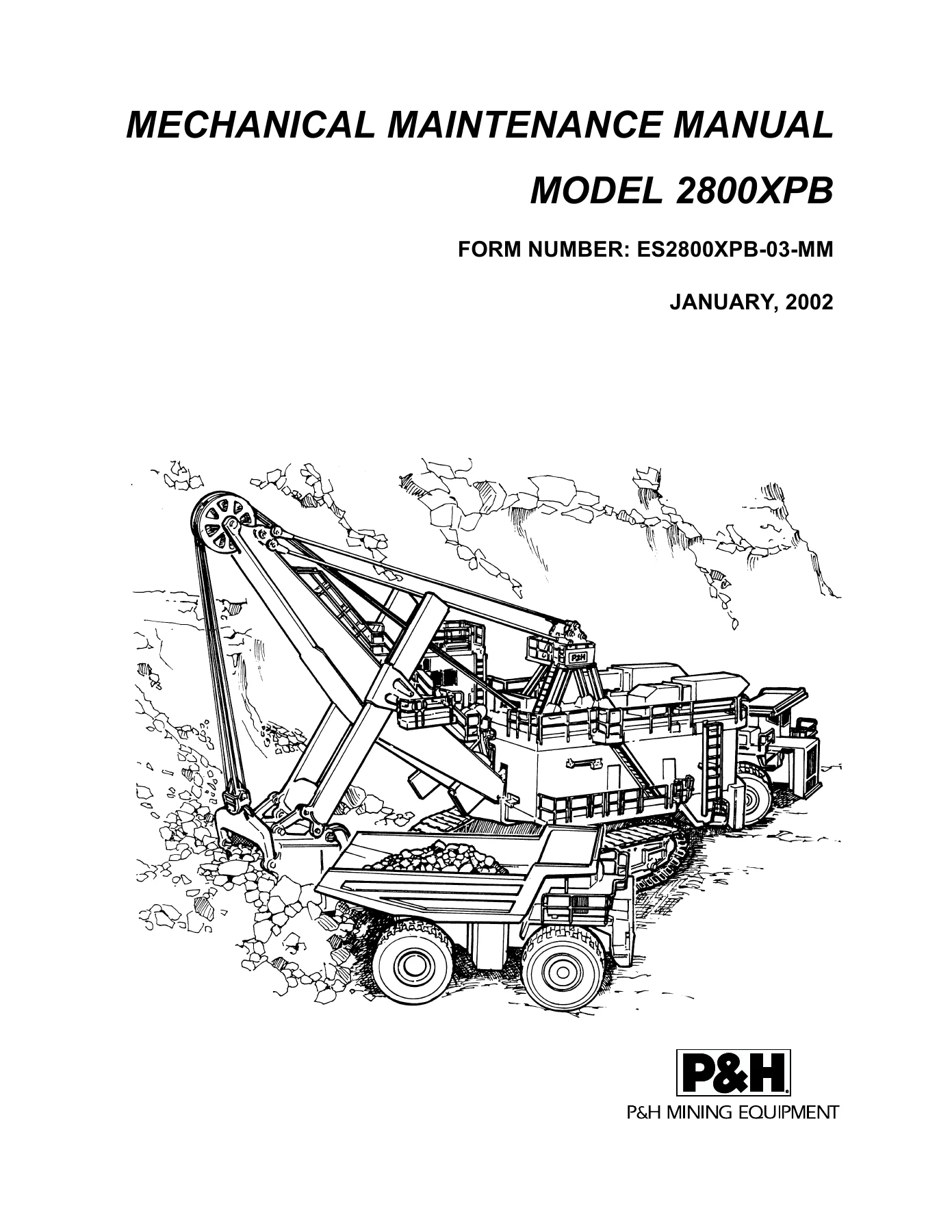
P&H 2800XPB Mechanical Maintenance Manual
This is the complete P&H 2800XPB Mechanical Maintenance Manual (Form ES2800XPB-03-MM, January 2002) for the 2800XPB Series B DC Electrotorque-Plus mining shovel. It is the full mechanical service reference used by mine maintenance crews to inspect, repair, disassemble, assemble, and adjust the major mechanical systems of the 2800XPB machine. Every subsystem is covered in dedicated sections with inspection intervals, torque values, component weights, wear limits, removal and installation steps, and exploded illustrations. Throughout the document, safety warnings, lockout/tagout instructions, and component-specific cautions are preserved exactly as issued.
File Details
- Manual type: Mechanical Maintenance Manual
- Brand: P&H Mining Equipment (Harnischfeger Corporation)
- Model: 2800XPB (Series B, DC Electrotorque-Plus mining shovel)
- Document number: ES2800XPB-03-MM
- Publication date: January 2002
- Language: English
- Page count: 730 pages
- File format: PDF
Chapters Covered
- Section 1 – Introduction: scope, general information, serial number location, safety precautions, lockout and tagout, sign maintenance, MSDS, warranty, mining shovel description, terminology, tabulated data, SuperNuts
- Section 2 – House Assembly: house assembly, hatch cover removal and installation, canopy and house section removal and installation, ventilation and filtration system, filter cell cleaning, adjustments
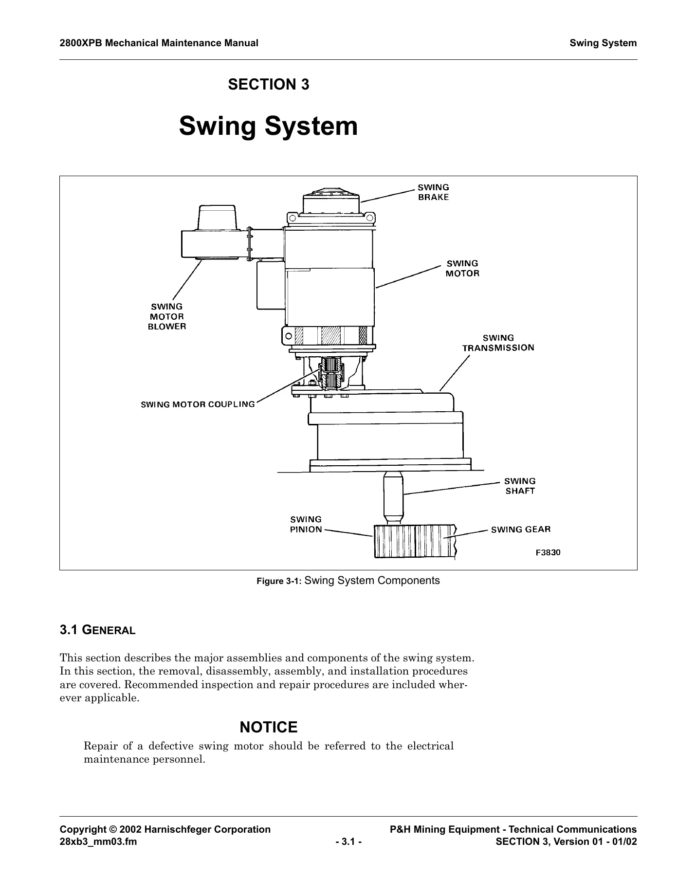
- Section 3 – Swing System: swing motor and blower (100J5948F2), swing transmission (100J5949F4), swing shaft (100J5950F1), swing brake, swing roller circle system, swing gear (R6216D1), swing ring gear installation, center gudgeon assembly (R17731), key interlock system, high voltage isolation, collector systems, upper main high voltage cabinet, collector guard access doors
- Section 4 – Hoist System: remote hoist controller, hoist ropes, hoist motor and blower (916J174F3), hoist disc brake, hoist gearcase (914J364F2), first reduction input shaft (910J664F2), intermediate hoist shaft (R1927F1, F4), hoist drum shaft (910J640F6)
- Section 5 – Attachment Components: boom suspension cables, gantry (911J390F5), boom assembly (100J6527), boom point assembly (919N23F2), boom limit assembly, dipper trip assembly (100J6689), dipper trip motor and drum (923J79F2)
- Section 6 – Crowd System: crowd drive assembly (100J4494F4), crowd gearcase assembly, first reduction shaft (910J553F2), second reduction shaft (910J344F3), shipper shaft assembly (R11770), dipper handles (R11750), rack section replacement, crowd disc brake, crowd limit switch sensor (979J247F1)
- Section 7 – Propel System: propel motor, propel brake (15R15D7), propel motor blower, propel transmission (100J5800F2), crawler component maintenance, crawler track assembly, lower roller assembly (R19768F1, F2), front idler rollers (910J653F1), rear idler assembly (913N63F1), crawler drive shaft (910J665F1, F2), tensioning crawler side frame studs
- Section 8 – Air System: upper air system and controls (100J6250F2), redundant brake solenoid systems, lower air control panel, lube air pump control panel, quick release valve (36Z240D11, D12), solenoid valves, receiver drain system, air system pressure switches, air regulators, air lubricators, air filters, deicer, air system dryers, boarding stairway air system, boarding stairway air cylinder (38Q136), filter vibrator kit (R11233F1)
- Section 9 – Maintenance Welding: weld inspection, weld repairs, welding process, weld filler metals and electrodes, electrode handling and storage, weld preparation, weld repair steps, welding precautions for austenitic manganese steel (P&H 7), weld heating and PWHT, splicing requirements, welding guidelines, butt weld and fillet weld guidelines
- Section 10 – Lubrication System: electric motor lubrication, grease selection, automatic lubrication system (Lincoln and Farval), lubrication pumps, Farval components, Lincoln components, replacing lubrication components, hoist gearcase lubrication system (100J6526F2), swing gearcase lubrication (R10044F1, F2), crowd gearcase lubrication system (R47958F1), oil filters (46U110D1, D2), oil strainer (46Q108), lubrication pump (37Z331D2), flexible couplings, gear reducer (53Z801), gearcase capacities, lubrication specifications
- Section 11 – Disc Brakes: disc brake operation, brake hold mode, hoist/crowd/propel/swing brakes, releasing disc brakes for maintenance, inspecting disc brakes, disc brake data for swing (15R14D1), crowd (15R13D3), propel (15R15D7), and hoist (R27275D1), removing air gap split shims, removing and installing disc brakes, shimming the swing brake, removing and replacing O-ring and felt seals
- Appendix A – Air Compressors: Sullair Type ES-8 rotary screw compressor (R36961), Quincy rotary screw compressor, Quincy reciprocating piston type compressor
- Appendix B – Air Dryers: membrane air dryer (R37969F1/F2), desiccant air dryer system (100J6572), air dryer (46Q121), after filter (46Z469), oil removal filter (46Z406)
- Appendix C – SnubRite Hydraulic Snubber: description, nameplates and decals, serial number plate, installation, mounting lugs, maintenance, rebuild schedule, repair parts
This manual is built around the actual 2800XPB machine systems. Each section carries the recommended inspection intervals (many at 250, 500, 750, or 1,000 hours), the correct component weights for rigging, the specified torque values for critical fasteners, and the tolerance or wear limits that determine when a part needs replacement. Where a specific service procedure carries risk, the manual spells out the exact sequence – for example, releasing the swing brake several times before removing the swing motor, using a SuperNut removal procedure in multiple graduated rounds, or verifying shaft alignment to a 0.003-inch total indicator runout before installing a coupling. The manual also contains detailed hydraulic, pneumatic, and lubrication schematics plus exploded views of the major shaft, brake, and gearcase assemblies.
What This Manual Enables You To Do
The 2800XPB Mechanical Maintenance Manual gives a mine maintenance crew the information needed to safely remove, disassemble, inspect, repair, reassemble, and install the machine’s major mechanical assemblies. That includes:
- Removing and reinstalling the swing motors, transmissions, and swing shaft while preserving the correct shim packs
- Disassembling and reassembling the hoist gearcase, first reduction shaft, intermediate shafts, and hoist drum shaft
- Servicing the crowd gearcase, first and second reduction shafts, shipper shaft, saddle blocks, and dipper handle racks
- Overhauling the crawler drive shafts, rollers, idlers, and track assemblies on the propel system
- Inspecting and repairing the air system, from the upper and lower control panels through the brake solenoids and air dryers
- Reading and applying the disc brake piston travel limits, air gap minimums, and shimming procedures for the hoist, crowd, swing, and propel brakes
- Following the correct welding procedures for the dipper handles, gantry, boom, and other structural components, including preheat and interpass temperatures for austenitic manganese steel
- Maintaining the automatic lubrication system and the individual gearcase lube circuits, including filter and strainer service
- Adjusting the shipper shaft axial end play, vertical and lateral saddle block slide plates, and the center gudgeon nut
Having the correct procedure, the correct torque, and the correct wear limit matters on a machine of this size. A shipper shaft or swing shaft that is re-shimmed incorrectly, a brake that is shimmed to the wrong air gap, or a hoist drum seal that is seated at the wrong depth will produce premature failures that can be far more expensive than the repair itself. This manual provides those exact values and the sequence the manufacturer recommends.
Complete PDF Bookmark Tree
Complete Bookmarks
The complete bookmarks in the “P&H 2800XPB Mining Shovel Mechanical Maintenance Manual – ES2800XPB-03-MM” are as follows:
Prefacep. 2
Table of Contentsp. 4
List of Figuresp. 18
List of Tablesp. 28
P&H® Mining Equipment Officesp. 32
Safe Operating Practicesp. 36
Definitions of Warningsp. 46
+Introductionp. 48
1.1 Scopep. 48
1.2 General Informationp. 48
1.3 Serial Number Locationp. 48
1.4 General Safety Precautionsp. 49
1.5 Lockout and Tagout Proceduresp. 49
1.6 Sign Maintenancep. 50
1.7 Reader Comment Formp. 50
1.8 Material Safety Data Sheets (MSDS)p. 50
1.9 Warrantyp. 51
+1.10 Mining Shovel Descriptionp. 51
1.10.1 Electrical Systemsp. 51
1.10.2 Hoist Systemp. 51
1.10.3 Crowd Systemp. 51
1.10.4 Swing Systemp. 53
1.10.5 Propel Systemp. 53
1.10.6 Brake Systemsp. 53
1.11 Mining Shovel Terminologyp. 53
+1.12 Tabulated Datap. 55
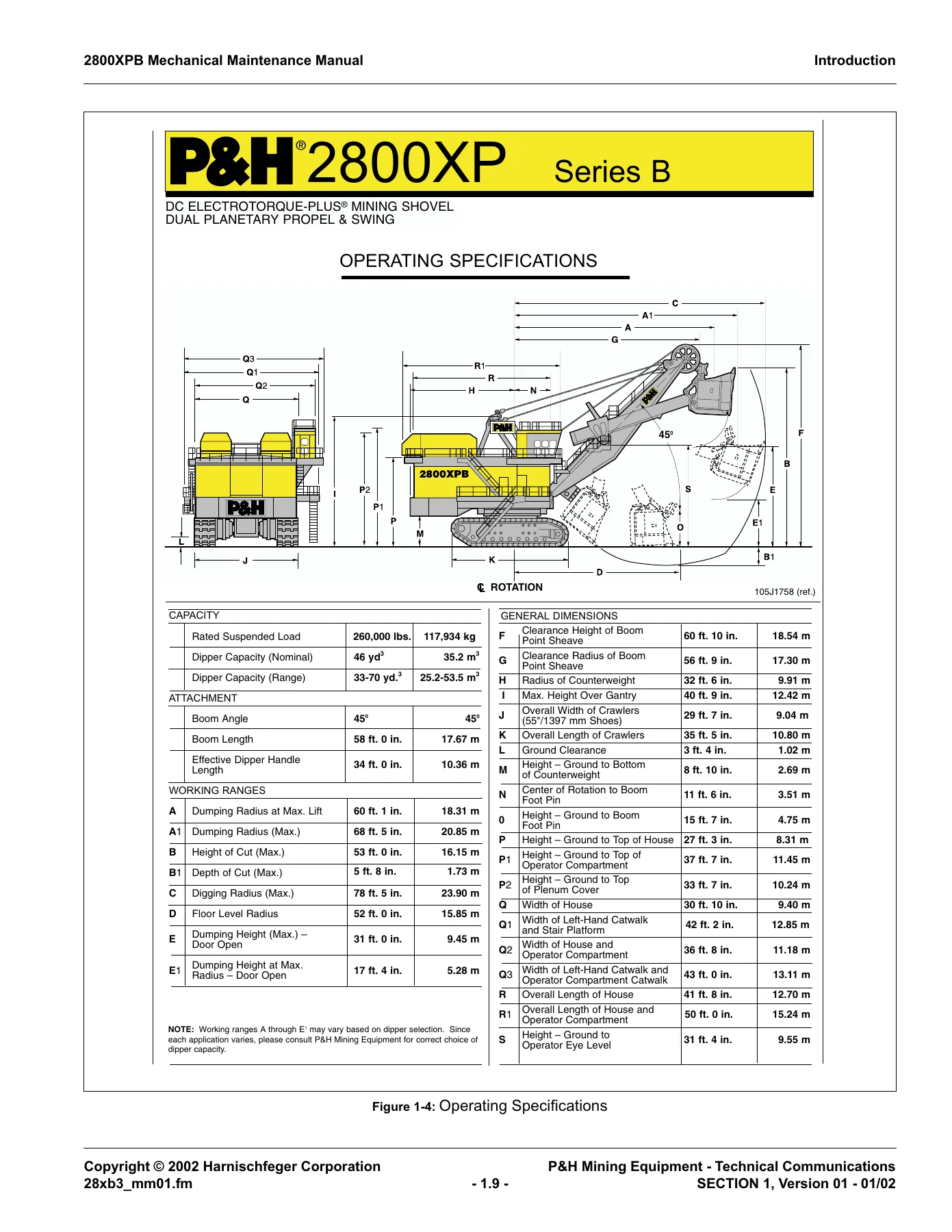
1.12.1 Operating Specificationsp. 55
1.12.2 Torque Valuesp. 55
1.12.3 Metric Conversionsp. 55
+1.13 Supernuts™p. 61
+1.14 Tensioning With Supernuts™p. 62
1.14.1 SuperNuts™ Removal Procedure (Service under 250˚F)p. 64
+House Assemblyp. 66
2.1 Generalp. 66
+2.2 House Assemblyp. 66
2.2.1 Descriptionp. 66
2.2.2 Hatch Cover Removalp. 66
2.2.3 Hatch Cover Installationp. 67
2.2.4 Canopy and House Section Removalp. 67
2.2.5 Canopy and House Section Installationp. 69
+2.3 House Ventilation And Filtration Systemp. 69
2.3.1 Descriptionp. 69
2.3.2 Inspectionp. 69
2.3.3 Filter Cell Cleaningp. 71
2.3.4 Adjustmentsp. 73
+Swing Systemp. 76
3.1 Generalp. 76
3.2 Descriptionp. 77
+3.3 Swing Motor And Blower (100J5948F2)p. 77
3.3.1 Descriptionp. 77
3.3.2 Inspection and Repairp. 77
3.3.3 Swing Motorp. 78
3.3.4 Swing Motor Blowerp. 82
+3.4 Swing Transmission (100J5949F4)p. 83
3.4.1 Generalp. 83
3.4.2 Descriptionp. 83
3.4.3 Inspectionp. 83
3.4.4 Removalp. 85
3.4.5 Installationp. 87
+3.5 Swing Shaft (100J5950F1)p. 89
3.5.1 Descriptionp. 89
3.5.2 Inspection and Repairp. 90
3.5.3 Removalp. 90
3.5.4 Disassemblyp. 92
3.5.5 Cleaning, Inspection, and Repairp. 93
3.5.6 Assemblyp. 93
3.5.7 Installationp. 94
3.5.8 Swing Shaft Bearing Capsule Replacementp. 95
3.6 Swing Brakep. 97
+3.7 Swing Roller Circle Systemp. 97
3.7.1 Roller Circle Assembly (R17563F1, R31980F1)p. 103
3.7.2 Swing Roller Circle Inspectionp. 105
3.7.3 Swing System Lubrication Inspectionp. 109
+3.8 Swing Gear (R6216D1)p. 111
3.8.1 Descriptionp. 111
3.8.2 Inspection and Repairp. 112
3.8.3 Tooth Repairp. 112
3.9 Swing Ring Gear Installationp. 112
+3.10 Center Gudgeon Assembly (R17731)p. 114
3.10.1 Gudgeon Nut Adjustmentp. 119
+3.11 Key Interlock Systemp. 122
3.12 High Voltage Isolationp. 123
3.13 Exiting High Voltage Areasp. 130
+3.14 Padlocksp. 130
3.14.1 General Padlock Placementp. 131
3.15 High Voltage Collectorp. 131
3.16 Low Voltage Collectorp. 135
+3.17 Upper Main High Voltage Cabinetp. 137
3.17.1 Entrance Procedurep. 137
+3.18 Installation Of Collector Guard Access Doorsp. 139
3.18.1 Generalp. 139
3.18.2 Tools and Materials Requiredp. 139
3.18.3 Cutting Openings and Installing Coversp. 140
+Hoist Systemp. 144
4.1 Descriptionp. 144
+4.2 Remote Hoist Controller (Optional)p. 145
4.2.1 Overviewp. 145
4.2.2 Procedurep. 145
+4.3 Hoist Ropesp. 148
4.3.1 Inspectionp. 148
4.3.2 Hoist Rope Reevingp. 149
+4.4 Hoist Motor And Blower (916J174F3)p. 149
4.4.1 Descriptionp. 149
4.4.2 Hoist Motor Removalp. 150
4.4.3 Hoist Motor Installationp. 153
+4.4.4 Motor Blower Assembly (R12599D1F1)p. 158
4.4.4.1 Descriptionp. 158
4.4.4.2 Removalp. 158
4.4.4.3 Repairp. 158
4.4.4.4 Installationp. 159
4.5 Hoist Disc Brakep. 160
+4.6 Hoist Gearcase (914J364F2)p. 160
4.6.1 Generalp. 160
4.6.2 Descriptionp. 161
4.6.3 Hoist Gearcase Mountingp. 161
4.6.4 Inspection And Repairp. 163
+4.6.5 Hoist Gearcase Disassemblyp. 164
4.6.5.1 Generalp. 164
4.6.5.2 Preliminary Preparationp. 164
4.6.5.3 Gearcase Cover Removalp. 165
4.6.5.4 Intermediate Shaft Assembly Removalp. 168
4.6.5.5 First Reduction (Input) Shaft Removalp. 170
4.6.5.6 Hoist Drum Shaft Removalp. 172
+4.6.6 Hoist Gearcase Assemblyp. 174
4.6.6.1 Generalp. 174
4.6.6.2 Preliminary Preparationp. 174
4.6.6.3 First Reduction (Input) Shaft Installationp. 174
4.6.6.4 Hoist Drum Sealsp. 174
4.6.6.5 Hoist Drum Shaft Installationp. 177
4.6.6.6 Intermediate Hoist Shaft Installationp. 178
4.6.6.7 Hoist Side Stand Shimmingp. 179
4.6.6.8 Hoist Gearcase Cover Installationp. 180
4.6.7 Post Assembly Proceduresp. 183
+4.7 First Reduction (Input) Shaft Assembly (910J664F2)p. 184
4.7.1 Descriptionp. 184
4.7.2 Inspectionp. 184
4.7.3 First Reduction (Input) Shaft Disassemblyp. 184
4.7.4 Inspection and Repairp. 186
4.7.5 First Reduction (Input) Shaft Assemblyp. 186
+4.8 Intermediate Hoist Shaft (R1927F1, F4)p. 189
4.8.1 Descriptionp. 189
4.8.2 Inspectionp. 190
4.8.3 Hoist Intermediate Shaft Disassemblyp. 190
4.8.4 Repairp. 190
4.8.5 Hoist Intermediate Shaft Assemblyp. 192
+4.9 Hoist Drum Shaft (910J640F6)p. 194
4.9.1 Descriptionp. 194
4.9.2 Inspection and Repairp. 194
4.9.3 Hoist Drum Shaft Disassemblyp. 197
+4.9.4 Hoist Drum Shaft Repairp. 198
4.9.4.1 Repair Hoist Drum Lagging Groovesp. 198
4.9.4.2 Replacing Removable Hoist Drum Laggingp. 198
4.9.5 Hoist Drum Shaft Assemblyp. 200
+Attachment Componentsp. 204
5.1 Generalp. 204
5.2 Descriptionp. 204
+5.3 Boom Suspension Cablesp. 205
5.3.1 Descriptionp. 205
5.3.2 Inspectionp. 205
5.3.3 Replacement Criteriap. 206
5.3.4 Repairp. 206
+5.4 Gantry (911J390F5)p. 206
5.4.1 Descriptionp. 206
5.4.2 Inspectionp. 207
5.4.3 Repairp. 208
+5.5 Boom Assembly (100J6527)p. 209
5.5.1 Descriptionp. 209
5.5.2 Inspection and Repairp. 210
+5.6 Boom Point Assembly (919N23F2)p. 212
5.6.1 Descriptionp. 212
5.6.2 Service And Repairp. 214
5.6.3 Removalp. 214
5.6.4 Disassemblyp. 215
5.6.5 Assemblyp. 216
5.6.6 Installationp. 217
+5.7 Boom Limit Assemblyp. 218
5.7.1 Descriptionp. 218
5.7.2 Boom Jackingp. 218
5.7.3 Boom Limit Switch (100J6493F4)p. 219
5.7.4 Boom Resolver Assembly (R40654F2)p. 221
+5.8 Dipper Trip Assembly (100J6689)p. 224
5.8.1 Descriptionp. 224
5.8.2 Inspection and Repairp. 226
+5.9 Dipper Trip Motor And Drum Assembly (923J79F2)p. 226
5.9.1 Descriptionp. 226
5.9.2 Removalp. 228
5.9.3 Disassemblyp. 230
5.9.4 Inspectionp. 231
5.9.5 Repairp. 231
5.9.6 Assemblyp. 233
5.9.7 Installationp. 235
+Crowd Systemp. 236
6.1 Generalp. 236
6.2 Descriptionp. 236
+6.3 Crowd Drive Assembly (100J4494F4)p. 237
6.3.1 Descriptionp. 237
6.3.2 Preliminary Proceduresp. 238
6.3.3 Crowd Motor Inspectionp. 239
6.3.4 Crowd Motor Repairp. 239
6.3.5 Crowd Motor Removalp. 239
6.3.6 Crowd Motor Installationp. 240
6.3.7 Crowd Belt Casep. 241
6.3.8 Crowd Motor Sheavep. 241
6.3.9 Power Band™ Belt Adjustmentp. 243
+6.3.10 Power Band™ Replacementp. 245
6.3.10.1 Preliminary Proceduresp. 245
6.3.10.2 Replacementp. 246
+6.4 Crowd Gearcase Assemblyp. 247
6.4.1 Generalp. 247
6.4.2 Crowd Gearcase Inspectionp. 248
6.4.3 Crowd Gearcase Repairsp. 248
+6.4.4 Crowd Gearcase Disassemblyp. 248
6.4.4.1 Generalp. 248
6.4.4.2 Preliminary Proceduresp. 249
6.4.4.3 Dipper Handle Removalp. 249
6.4.4.4 Saddle Block Removalp. 251
6.4.4.5 Crowd Gearcase Cover Removalp. 253
6.4.4.6 First Reduction Shaft Removalp. 253
6.4.4.7 Second Reduction Shaft Removalp. 255
6.4.4.8 Shipper Shaft Removalp. 256
+6.4.5 Crowd Gearcase Assemblyp. 257
6.4.5.1 Generalp. 257
6.4.5.2 Shipper Shaft Installationp. 257
6.4.5.3 First Reduction Shaft Installationp. 257
6.4.5.4 Second Reduction Shaft Installationp. 258
6.4.5.5 Crowd Gearcase Cover Installationp. 259
6.4.6 Dipper Handle Installationp. 259
+6.4.7 Shipper Shaft Axial Clearance Adjustmentsp. 260
6.4.7.1 Generalp. 260
6.4.7.2 Inspectionp. 260
6.4.7.3 Shipper Shaft Axial Clearance Adjustmentp. 263
6.4.8 Vertical Saddle Block Slide Plate Adjustmentp. 266
6.4.9 Lateral Saddle Block Slide Plate Adjustmentp. 268
6.4.10 Contingent Lateral Saddle Block Slide Plate Adjustmentp. 269
+6.5 First Reduction Shaft (910J553F2)p. 270
6.5.1 Descriptionp. 270
6.5.2 First Reduction Shaft Removalp. 270
6.5.3 First Reduction Shaft Disassemblyp. 271
6.5.4 First Reduction Shaft Inspectionp. 271
6.5.5 First Reduction Shaft Repairp. 271
6.5.6 First Reduction Shaft Assemblyp. 274
6.5.7 First Reduction Shaft Installationp. 275
+6.6 Second Reduction Shaft (910J344F3)p. 276
6.6.1 Descriptionp. 276
6.6.2 Second Reduction Shaft Removalp. 276
6.6.3 Second Reduction Shaft Disassemblyp. 278
6.6.4 Second Reduction Shaft Inspectionp. 278
6.6.5 Second Reduction Shaft Repairp. 278
6.6.6 Second Reduction Shaft Assemblyp. 278
6.6.7 Second Reduction Shaft Installationp. 280
+6.7 Shipper Shaft Assembly (R11770)p. 280
6.7.1 Descriptionp. 280
6.7.2 Shipper Shaft Removal and Disassemblyp. 282
6.7.3 Shipper Shaft Inspectionp. 285
6.7.4 Shipper Shaft Repairp. 287
6.7.5 Shipper Shaft Gear Shimmingp. 287
6.7.6 Shipper Shaft Assembly and Installationp. 288
+6.8 Dipper Handles (R11750)p. 290
6.8.1 Generalp. 290
6.8.2 Descriptionp. 291
6.8.3 Visual Inspectionp. 291
6.8.4 Weld Inspectionp. 292
6.8.5 Dimensional Inspectionp. 292
6.8.6 Dipper Handle Spacer Installationp. 295
6.8.7 Repairing Dipper Handle Cracksp. 296
6.8.8 Dipper Handle Rack Replacementp. 297
6.8.9 Welding Rack Sectionsp. 298
+6.8.10 Installing Rack Sectionsp. 302
6.8.10.1 Dimensions To Maintainp. 302
6.8.11 Rack Installation Procedure – Manganese Racksp. 303
6.8.12 Rack Installation – Alloy Racksp. 312
6.9 Rack Section Replacementp. 319
6.10 Crowd Disc Brakep. 320
+6.11 Crowd Limit Switch Sensor (979J247F1)p. 321
6.11.1 Descriptionp. 321
6.11.2 Variable Transformer (Resolver) Replacementp. 321
6.11.3 Limit Switch Sensor Removalp. 322
6.11.4 Limit Switch Sensor Installationp. 323
+Propel Systemp. 324
7.1 Generalp. 324
7.2 Descriptionp. 324
+7.3 Propel Motorp. 324
7.3.1 Generalp. 324
7.3.2 Descriptionp. 324
7.3.3 Inspectionp. 326
7.3.4 Repairp. 326
7.3.5 Propel Motor Removalp. 327
7.3.6 Propel Motor Installationp. 328
+7.3.7 Propel Motor Alignmentp. 330
7.3.7.1 Generalp. 330
7.3.7.2 Horizontal Angularity Alignmentp. 331
7.3.7.3 Horizontal Offset Alignmentp. 332
7.3.7.4 Vertical Parallelism Alignmentp. 332
7.3.7.5 Vertical Offset Alignmentp. 333
7.3.7.6 Final Alignment Proceduresp. 334
7.3.7.7 Facial Gap Adjustmentp. 334
7.4 Propel Brake (15R15D7)p. 335
+7.5 Propel Motor Blowerp. 335
7.5.1 Removalp. 335
7.5.2 Repairp. 335
7.5.3 Installationp. 335
+7.6 Propel Transmission (100J5800F2)p. 335
7.6.1 Descriptionp. 335
7.6.2 Removalp. 336
7.6.3 Repairp. 339
+7.6.4 Installationp. 340
7.6.4.1 Generalp. 340
7.6.4.2 Installation Procedurep. 341
+7.7 Crawler Component Maintenancep. 343
7.7.1 Introductionp. 343
+7.7.2 Pitch Mismatch and Track Tension Inspectionp. 345
7.7.2.1 Generalp. 345
7.7.2.2 Inspection Procedurep. 345
7.7.3 Pitch Mismatch Solutionsp. 349
7.7.4 Results of Appropriate Repairsp. 349
7.7.5 Additional Track Repair Optionsp. 351
+7.8 Crawler Track Assemblyp. 351
7.8.1 Descriptionp. 351
7.8.2 Inspectionp. 351
7.8.3 Track Removalp. 352
+7.8.4 Repairing Crawler Shoesp. 353
7.8.4.1 Crawler Belt Installationp. 354
7.8.4.2 Crawler Track Adjustmentp. 355
+7.9 Lower Roller Assembly (R19768F1, F2)p. 357
7.9.1 Descriptionp. 357
7.9.2 Inspectionp. 359
7.9.3 Removal and Disassemblyp. 360
7.9.4 Repairsp. 360
7.9.5 Installation and Assemblyp. 361
+7.10 Front Idler Rollers (910J653F1)p. 363
7.10.1 Descriptionp. 363
7.10.2 Inspectionp. 365
7.10.3 Removal and Disassemblyp. 366
7.10.4 Repairp. 367
7.10.5 Assembly and Installationp. 369
+7.11 Rear Idler Assembly (913N63F1)p. 370
7.11.1 Generalp. 370
7.11.2 Descriptionp. 370
7.11.3 Inspectionp. 370
7.11.4 Removal and Disassemblyp. 371
7.11.5 Repairp. 372
7.11.6 Assembly and Installationp. 373
+7.12 Crawler Drive Shaft (910J665F1, F2)p. 375
7.12.1 Descriptionp. 375
7.12.2 Inspectionp. 375
7.12.3 Removal and Disassemblyp. 375
7.12.4 Repairp. 380
7.12.5 Assembly and Installationp. 380
+7.13 Tensioning Crawler Side Frame Studsp. 382
7.13.1 Side Frame Rod Bolt Tensioning Values – Various Methodsp. 382
+7.13.2 Side Frame Rod Bolt Tensioning with Hydraulic Kit (R17981F3, F4)p. 384
7.13.2.1 Generalp. 384
7.13.2.2 Procedure for Tensioning Side Frame Rod Boltsp. 385
+Air Systemp. 390
+8.1 Descriptionp. 390
8.1.1 Generalp. 390
8.1.2 Upper Air System and Controls (100J6250F2)p. 391
8.1.3 Redundant Brake Solenoid Systemsp. 393
8.1.4 Causes of Redundant Crossover System Failuresp. 397
8.1.5 Valve Failure Test Procedurep. 397
8.1.6 Preventive Maintenancep. 400
8.1.7 Immediate Causes of Valve Failuresp. 400
8.1.8 Underlying Causes of Valve Failuresp. 401
8.1.9 Lower Air Control Panelp. 401
8.2 Lube Air Pump Control Panelp. 402
+8.3 Quick Release Valve (36Z240D11, D12)p. 403
8.3.1 Descriptionp. 403
8.3.2 Maintenance and Repairp. 404
+8.4 Solenoid Valvesp. 405
8.4.1 Generalp. 405
8.4.2 Solenoid Brake Valvesp. 405
8.4.3 Solenoid Valve Maintenancep. 406
+8.5 Receiver Drain Systemp. 407
+8.6 Air System Pressure Switchesp. 408
8.6.1 Air Receiver Pressure Switchp. 408
8.6.2 Brake System Pressure Switchesp. 409
+8.7 Air Regulatorsp. 411
8.7.1 Generalp. 411
8.7.2 Air Regulator – Upper Brakes and Lubricationp. 411
8.7.3 Air Regulator/Filter – Solenoid Spool Assistp. 412
8.7.4 Adjustmentp. 414
8.7.5 Disassemblyp. 414
8.7.6 Inspectionp. 414
8.7.7 Assemblyp. 414
8.7.8 Troubleshootingp. 414
+8.8 Air Lubricator (46Z405)p. 415
8.8.1 Maintenancep. 415
8.8.2 Repairp. 415
+8.9 Air Lubricator (46Q38D9)p. 418
8.9.1 Descriptionp. 418
8.9.2 Lubricator Adjustmentp. 418
+8.10 Air Filtersp. 419
8.10.1 Air System And Boarding Stairway (46Z355D4 and 46Q39D9)p. 419
8.10.2 Air Filter – Brake Valve Pilot (46Z515)p. 421
8.11 Deicerp. 421
8.12 Air System Dryersp. 422
+8.13 Boarding Stairway Air Systemp. 422
8.13.1 Descriptionp. 422
8.13.2 Boarding Stairway Componentsp. 423
8.13.3 Air Filterp. 426
8.13.4 Air Lubricatorp. 426
8.13.5 Air Pressure Regulatorp. 426
+8.14 Boarding Stairway Air Cylinder (38Q136)p. 427
8.14.1 Descriptionp. 427
8.14.2 Removalp. 428
8.14.3 Disassemblyp. 428
8.14.4 Inspectionp. 429
8.14.5 Assemblyp. 429
8.14.6 Installationp. 430
8.15 Filter Vibrator Kit (R11233F1)p. 430
+Maintenance Weldingp. 432
9.1 Generalp. 432
9.2 Introductionp. 432
+9.3 Weld Inspectionp. 433
9.3.1 Regular Inspectionp. 433
9.3.2 Unscheduled Inspectionp. 433
+9.3.3 Preparation for Inspectionp. 433
9.3.3.1 Surface Cleaningp. 433
9.3.3.2 Access Doors and Holesp. 433
9.3.3.3 Scaffolding and Bracket Attachmentp. 434
+9.4 Weld Repairsp. 434
9.4.1 Type of Weld Repairp. 434
9.4.2 Base Metal Assessmentp. 434
9.4.3 Weld Repair Assessmentp. 435
+9.5 Welding Processp. 435
9.5.1 Weld Process Selectionp. 435
+9.5.2 Weld Process Factorsp. 435
9.5.2.1 Base Metal Typep. 435
9.5.2.2 Joint Design and Thicknessp. 436
9.5.2.3 Welding Positionp. 436
9.5.2.4 Environmental Conditionsp. 436
9.5.2.5 Availability of Equipmentp. 436
9.5.2.6 Weld Process Summaryp. 437
+9.6 Weld Filler Metals and Electrodesp. 437
9.6.1 Filler Metal Selectionp. 437
9.6.2 Filler Metal and Electrode Classificationsp. 437
9.6.3 Electrode Handling and Storagep. 438
+9.7 Weld Preparationp. 448
9.7.1 Types of Weld Defectsp. 448
9.7.2 Weld Preparation Stepsp. 448
9.8 Weld Repair Stepsp. 449
+9.9 Welding Precautions For Austenitic Manganese Steel (P&H 7)p. 454
9.9.1 Weld Defect Repairp. 456
+9.10 Weld Heating (Other Than Austenitic Manganese Steel)p. 457
9.10.1 Weld Preheat Guidelinesp. 457
9.10.2 Post Weld Heat Treatment (PWHT)p. 457
9.11 Weld Repair – Final Cleaning and Finishp. 457
+9.12 Splicing Requirementsp. 458
9.12.1 One-Inch Plates and Underp. 458
9.12.2 Plates Over One Inchp. 458
+9.12.3 Control of Distortion and Shrinkagep. 458
9.12.3.1 Angular Distortionp. 458
9.12.3.2 Transverse Shrinkagep. 458
9.12.4 Complete Penetration of Groove Weldp. 459
+9.13 Welding Guidelinesp. 459
9.13.1 Scopep. 459
9.13.2 Purposep. 460
9.13.3 Weld Definitionsp. 460
+9.13.4 Bead and Fillet Weld Guidelinesp. 462
9.13.4.1 Convexity of Fillet Weldsp. 464
9.13.4.2 Concavity of Fillet Weldsp. 465
+9.13.5 Butt Weld Guidelinesp. 466
9.13.5.1 Undercut and Washp. 466
9.13.5.2 Overlapp. 467
9.13.5.3 Porosityp. 468
9.13.5.4 Slag Inclusionsp. 468
9.13.5.5 Lack of Fusionp. 469
9.13.5.6 Crater Cracksp. 469
9.13.5.7 Cratersp. 469
9.13.5.8 Standards for Weld Grindingp. 470
9.13.5.9 Weld Symbol Definitionsp. 470
+Lubrication Systemp. 472
10.1 Descriptionp. 472
+10.2 Electric Motor Lubricationp. 473
10.2.1 Generalp. 473
10.2.2 Lubricationp. 473
10.2.3 Lubrication Intervalsp. 473
10.2.4 Lubrication Proceduresp. 474
10.3 Grease Selectionp. 476
10.4 Installing Replacement Motorp. 481
10.5 Lubrication After Extended Storagep. 481
+10.6 Automatic Lubrication Systemp. 482
10.6.1 Description of Controlsp. 482
10.6.2 Operating in Cold Conditionsp. 487
+10.6.3 Lube Room Control Panelsp. 487
10.6.3.1 Generalp. 487
10.6.3.2 Push-buttonsp. 489
10.6.3.3 Alarmsp. 490
10.6.4 Control Cabinetp. 491
+10.6.5 Control Cabinet Touchscreenp. 491
10.6.5.1 Generalp. 491
10.6.5.2 Checking Or Changing Preset Timesp. 492
10.7 Automatic Lubrication System Troubleshootingp. 495
10.8 Inspectionp. 496
10.9 System Operationp. 497
10.10 System Start-upp. 497
+10.11 Lubrication Pumpsp. 498
10.11.0.1 Descriptionp. 498
10.11.0.2 Repairp. 498
10.11.0.3 Installationp. 498
+10.12 Farval Componentsp. 500
+10.12.1 Measuring Valvesp. 500
10.12.1.1 Generalp. 500
10.12.1.2 Descriptionp. 500
10.12.1.3 Measuring Valve Operation – Type DD Valve Configured For Dual Dischargep. 500
10.12.1.4 Measuring Valve Operation – Type DD Valve Configured For Single Discharge And Type DM V…p. 502
10.12.1.5 Measuring Valve Adjustmentp. 503
10.12.1.6 Measuring Valve Removalp. 504
10.12.1.7 Type DM Measuring Valve Disassemblyp. 505
10.12.1.8 Measuring Valve Inspection And Repairp. 506
10.12.1.9 Type DM Measuring Valve Assemblyp. 506
10.12.1.10 Type DD Measuring Valve Disassemblyp. 507
10.12.1.11 Measuring Valve Inspection And Repairp. 507
10.12.1.12 Type DD Measuring Valve Assemblyp. 508
10.12.1.13 Measuring Valve Installationp. 509
+10.12.2 Reversing Valvesp. 509
10.12.2.1 Reversing Valve Operationp. 509
10.12.2.2 Reversing Valve Adjustmentp. 513
+10.13 Lincoln Componentsp. 514
10.13.1 Generalp. 514
10.13.2 Descriptionp. 514
+10.13.3 Injectorsp. 515
10.13.3.1 Descriptionp. 515
10.13.3.2 Injector Operation – SL-1 And SL-11p. 515
10.13.3.3 Injector Operation – SL-32p. 517
10.13.3.4 Injector Adjustment – SL-1 And SL-11p. 519
10.13.3.5 SL-32 Injector Adjustmentp. 520
10.13.3.6 SL-1 Injector Removalp. 521
10.13.3.7 SL-1 Injector Disassemblyp. 522
10.13.3.8 SL-1 Injector Repairp. 523
10.13.3.9 SL-1 Injector Assemblyp. 523
10.13.3.10 SL-1 Injector Installationp. 524
10.13.3.11 SL-11 Injector Removalp. 525
10.13.3.12 SL-11 Injector Disassemblyp. 525
10.13.3.13 SL-11 Injector Repairp. 526
10.13.3.14 SL-11 Injector Assemblyp. 526
10.13.3.15 SL-11 Injector Installationp. 527
10.13.3.16 SL-32 Injector Removalp. 527
10.13.3.17 SL-32 Injector Disassemblyp. 528
10.13.3.18 SL-32 Injector Repairp. 529
10.13.3.19 SL-32 Injector Assembly And Installationp. 529
+10.13.4 Vent Valve Assembliesp. 530
10.13.4.1 Generalp. 530
10.13.4.2 Descriptionp. 530
10.13.4.3 Vent Valve Assembly Operationp. 530
10.13.4.4 Vent Valve Removalp. 531
10.13.4.5 Vent Valve Disassemblyp. 532
10.13.4.6 Vent Valve Repairp. 532
10.13.4.7 Vent Valve Assemblyp. 532
10.13.4.8 Vent Valve Installationp. 533
10.13.4.9 Elbow Union Removal And Disassemblyp. 533
10.13.4.10 Elbow Union Repairp. 534
10.13.4.11 Elbow Union Assembly And Installationp. 534
+10.13.5 Spray Valves (R5808F3, F6)p. 535
10.13.5.1 Descriptionp. 535
10.13.5.2 Removalp. 535
10.13.5.3 Repairp. 536
+10.13.6 Pressure Switchesp. 537
10.13.6.1 Descriptionp. 537
10.13.6.2 Adjustmentp. 538
+10.14 Replacing Lubrication Componentsp. 538
10.14.1 Generalp. 538
+10.14.2 Descriptionp. 538
10.14.2.1 Removalp. 538
10.14.2.2 Installationp. 539
+10.14.3 Bleeding Air From Supply Linesp. 539
10.14.3.1 Bleeding Air From Supply Lines – Systemp. 540
10.14.3.2 Bleeding Air From Supply Lines – Component Replacementp. 542
10.14.3.3 Bleeding Air From Feeder Linesp. 543
+10.15 Hoist Gearcase Lubrication System (100J6526F2)p. 545
10.15.1 Descriptionp. 545
+10.15.2 Maintenancep. 546
10.15.2.1 Generalp. 546
10.15.2.2 Inspectionp. 546
+10.16 Swing Gearcase Lubrication (R10044F1, F2)p. 546
10.16.1 Descriptionp. 546
+10.16.2 Maintenancep. 548
10.16.2.1 Generalp. 548
10.16.2.2 Inspectionp. 548
+10.17 Crowd Gearcase Lubrication System (R47958F1)p. 548
10.17.1 Descriptionp. 548
+10.17.2 Maintenancep. 550
10.17.2.1 Generalp. 550
10.17.2.2 Inspectionp. 550
+10.17.3 Oil Filters (46U110D1, D2)p. 550
10.17.3.1 Descriptionp. 550
10.17.3.2 Disassemblyp. 551
10.17.3.3 Maintenancep. 552
10.17.3.4 Assemblyp. 552
+10.17.4 Oil Strainer (46Q108)p. 553
10.17.4.1 Servicingp. 554
+10.17.5 Lubrication Pump (37Z331D2)p. 554
10.17.5.1 Generalp. 554
10.17.5.2 Descriptionp. 554
10.17.5.3 Removalp. 556
10.17.5.4 Replacing The Shaft Sealp. 557
10.17.5.5 Disassemblyp. 558
10.17.5.6 Inspection And Repairp. 558
10.17.5.7 Assemblyp. 558
10.17.5.8 Installationp. 559
+10.18 Hoist And Crowd Lube Pump Flexible Coupling (18Z3706D2, D3)p. 559
10.18.1 Descriptionp. 559
10.18.2 Alignmentp. 560
+10.19 Swing Lube Pump Flexible Coupling (18Z3706D4)p. 561
10.19.1 Descriptionp. 561
10.19.2 Alignmentp. 561
+10.20 Gear Reducer (53Z801)p. 562
10.20.1 Descriptionp. 562
10.20.2 Maintenancep. 564
10.20.3 Removalp. 564
10.20.4 Disassemblyp. 564
10.20.5 Inspection and Repairp. 565
10.20.6 Assemblyp. 565
10.21 Gearcase Capacitiesp. 567
+10.22 Lubrication Specificationsp. 567
10.22.1 Generalp. 567
10.22.2 P&H Material Specificationsp. 567
10.22.3 P&H Material Specification 472 – Multi-Purpose Grease: Extreme Pressure (EP)p. 568
10.22.4 P&H Material Specification 464 – Open Gear Lubricantp. 568
10.22.5 P&H Material Specification 451 – Heavy Duty Motor Oilp. 569
10.22.6 P&H Material Specification 497 – Multi-Purpose Gear Oil – Single Viscosity; Extreme Press…p. 569
10.22.7 P&H Material Specification 520 – Multi-Service Mining Lubricantp. 570
10.22.8 Grease Versus Open Gear Lubep. 571
10.22.9 Selection of Gearcase Oilsp. 571
10.22.10 ISO Grades Of Oilp. 573
+Disc Brakesp. 574
11.1 Generalp. 574
+11.2 Disc Brake Operationp. 574
11.2.1 Generalp. 574
+11.2.2 Brake Hold Modep. 575
11.2.2.1 Causes of Brake Hold Modep. 575
11.2.2.2 Brake Hold Mode Overridep. 576
11.2.3 Hoist Brake(s)p. 577
11.2.4 Crowd Brakep. 577
11.2.5 Propel Brakep. 577
11.2.6 Swing Brakep. 578
+11.3 Releasing Disc Brakes For Maintenancep. 578
11.3.1 Descriptionp. 578
11.3.2 Preliminary Procedures for Releasing Brakesp. 579
+11.3.3 Releasing Hoist, Crowd, or Swing Brakes for Maintenancep. 579
11.3.3.1 Releasing Hoist, Crowd, or Swing Brakes Using the Operator’s Controlsp. 579
11.3.3.2 Releasing Hoist, Crowd, or Swing Brakes With an External Air Supplyp. 580
11.3.4 Releasing Propel Brakes for Maintenancep. 583
11.3.5 Disc Brakes That Can Not Be Releasedp. 584
+11.4 Inspecting Disc Brakesp. 585
11.4.1 Tools and Equipment Requiredp. 585
+11.4.2 Preventive Maintenance (PM) Inspection Every 250 Hoursp. 585
11.4.2.1 Generalp. 585
11.4.2.2 Visual Inspectionp. 585
11.4.2.3 Mechanical Inspectionp. 588
11.5 Other Inspectionsp. 593
+11.6 Disc Brake Datap. 594
11.6.1 Swing Brake (15R14D1)p. 594
11.6.2 Crowd Brake (15R13D3)p. 596
11.6.3 Propel Brake (15R15D7)p. 598
11.6.4 Hoist Brake (R27275D1)p. 600
11.6.5 Weightsp. 602
+11.7 Removing Air Gap Split Shimsp. 603
11.7.1 Tools and Equipment Requiredp. 603
11.7.2 Descriptionp. 603
11.7.3 Removing Air Gap Split Shims Procedurep. 604
+11.8 Removing Disc Brakes – Normal Conditionsp. 606
11.8.1 Tools and Equipment Requiredp. 606
11.8.2 Removing Disc Brakes Procedure (Normal)p. 607
+11.9 Removing Disc Brakes – Special Conditionsp. 609
11.9.1 Tools and Equipment Requiredp. 609
11.9.2 Descriptionp. 609
+11.10 Installing Disc Brakesp. 611
11.10.1 Tools and Equipment Requiredp. 611
11.10.2 Installing Disc Brakes Procedurep. 612
11.10.3 Shimming the Swing Brakep. 614
+11.11 Removing And Replacing O-ring and Felt Sealsp. 616
11.11.1 Generalp. 616
11.11.2 Tools and Equipment Requiredp. 616
11.11.3 Inspection for O-ring Leakagep. 617
+11.11.4 Removing and Replacing O-ringsp. 618
11.11.4.1 Remove And Replace O-rings On The Shovel As Follows:p. 619
+Air Compressorsp. 626
A.1 Descriptionp. 626
+A.2 Rotary Screw Compressor (R36961) Sullair Type Es-8p. 627
+A.2.1 Air Control Descriptionp. 632
A.2.1.1 Compressor Modulationp. 632
A.2.1.2 Compressor Unloadingp. 634
A.2.1.3 Compressor Programmed Set Pointsp. 635
A.2.1.4 Dual Compressor Operationp. 638
A.2.1.5 Touchpad Operationp. 640
A.2.1.6 Status Displaysp. 641
+A.3 Rotary Screw Compressor – Quincy Rotary Screwp. 643
A.3.1 Air Control Descriptionp. 647
+A.4 Quincy Reciprocating (Piston Type) Air Compressorp. 650
A.4.1 Generalp. 650
A.4.2 Lubricationp. 650
A.4.3 Oil Pressure Adjustmentp. 652
A.4.4 Adjusting Belt Tensionp. 652
+Air Dryersp. 654
B.1 Introductionp. 654
+B.2 Air Dryer (R37969F1/F2)p. 654
B.2.1 Generalp. 654
B.2.2 Operationp. 655
B.2.3 Maintenancep. 656
+B.3 Desiccant Air Dryer System (100J6572)p. 659
B.3.1 Generalp. 659
B.3.2 Descriptionp. 659
B.3.3 Air Dryer Inputp. 659
B.3.4 Air Dryer (46Q121)p. 662
B.3.5 Air Dryer Cyclesp. 664
B.3.6 Air Dryer Outputp. 666
B.3.7 Air Filter – Dryer After Filter (46Z469)p. 668
B.3.8 Air Filter – Oil Removal (46Z406)p. 669
+SnubRite® Hydraulic Snubberp. 672
+C.1 Introductionp. 672
C.1.1 Generalp. 672
C.1.2 Descriptionp. 672
C.1.3 SnubRite® Nameplates And Decalsp. 673
C.1.4 SnubRite® Serial Number Platep. 675
C.1.5 SnubRite® Product Warranty Registration Cardp. 675
+C.2 Installationp. 677
C.2.1 Generalp. 677
+C.2.2 Snubber Liftingp. 677
C.2.2.1 Descriptionp. 677
C.2.2.2 Snubber Lifting Procedurep. 677
C.2.3 Mounting Lugsp. 680
C.2.4 Installationp. 680
+C.2.5 Maintenancep. 682
C.2.5.1 Snubber Replacement Criteriap. 682
C.2.6 Rebuild Schedulep. 683
C.3 Repair Partsp. 684
Indexp. 686
Reader Comment Formp. 724
Why Buy This Manual
This is the full 730-page ES2800XPB-03-MM document – not a summary or a partial reprint. It contains the major assembly sections, the tabulated torque data, the inspection intervals, the exploded views, and the welding guidelines for the 2800XPB Series B shovel. Whether the machine is still in production or is going through a planned rebuild, the procedures in this manual are the reference point for keeping the mechanical systems within specification.
Instant PDF Delivery
The manual is delivered as an instant-download PDF. There is no shipping, no waiting for a physical book, and no regional restriction on the file. It can be stored on a shop computer, transferred to a tablet or laptop for use on the machinery deck, or printed and placed in a maintenance binder. Individual pages can be printed when a specific procedure is needed at the machine.


Reviews
There are no reviews yet.