Description
Epiroc Simba 1254 Maintenance Manual 2019 – PDF Workshop Guide
The Epiroc Simba 1254 Maintenance Manual is the complete scheduled-service and upkeep reference for this production drill rig. Published in 2019 under document number 10628142731.1.10628178827 en-US, this 188-page PDF walks a technician through every maintenance interval the machine requires – daily checks, 10-hour engine services, 50-hour inspections, 250-hour filter changes, 500-hour oil replacements, and the full 1000 and 2000-hour service routines. Whether you are responsible for a single Simba 1254 or a fleet of Epiroc drill rigs, this manual supplies the procedures, torque values, pressure settings, and component locations needed to keep the machine running.
File Details
- Manual type: Maintenance Manual
- Brand: Epiroc
- Model: Simba 1254
- Publication date: 2019-01-23
- Document number: 10628142731.1.10628178827 en-US
- Language: English
- Page count: 188 pages
- File format: PDF
Chapters Covered
- 1. Introduction – Safety First, Purpose of Publication, Target Group, Product Warranty
- 2. About Maintenance Management – Hour Meters, Maintenance Records, Oil Analysis
- 3. Specifications – Standard Tightening Torques for Bolted Joints
- 4. General Machine Condition – Wash Machine Externally, Examine Condition of Signs, Check Hatches and Locks
- 5. Fire Fighting Equipment – Check Fire Extinguishers, Loosen Powder, Check Actuators, Check Fire Fighting System
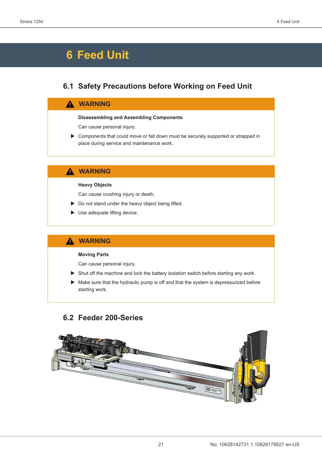
- 6. Feed Unit – Safety Precautions, Feeder 200-Series, Technical Data, Cradle Hinge Play, Rock Drill Retaining Bolts, Installing Rock Drill and Rotation Unit, Slide Pieces, Tightening Torque, Adjusting Cradle, Replacing Slide Rails, Length Sensor, Electrical Components, Hydraulic Box, Hydraulic Hoses, Hydraulic Cylinder, Lubricate Feeder, Disassembling and Assembling Feed Cylinder, Drill Rod Support
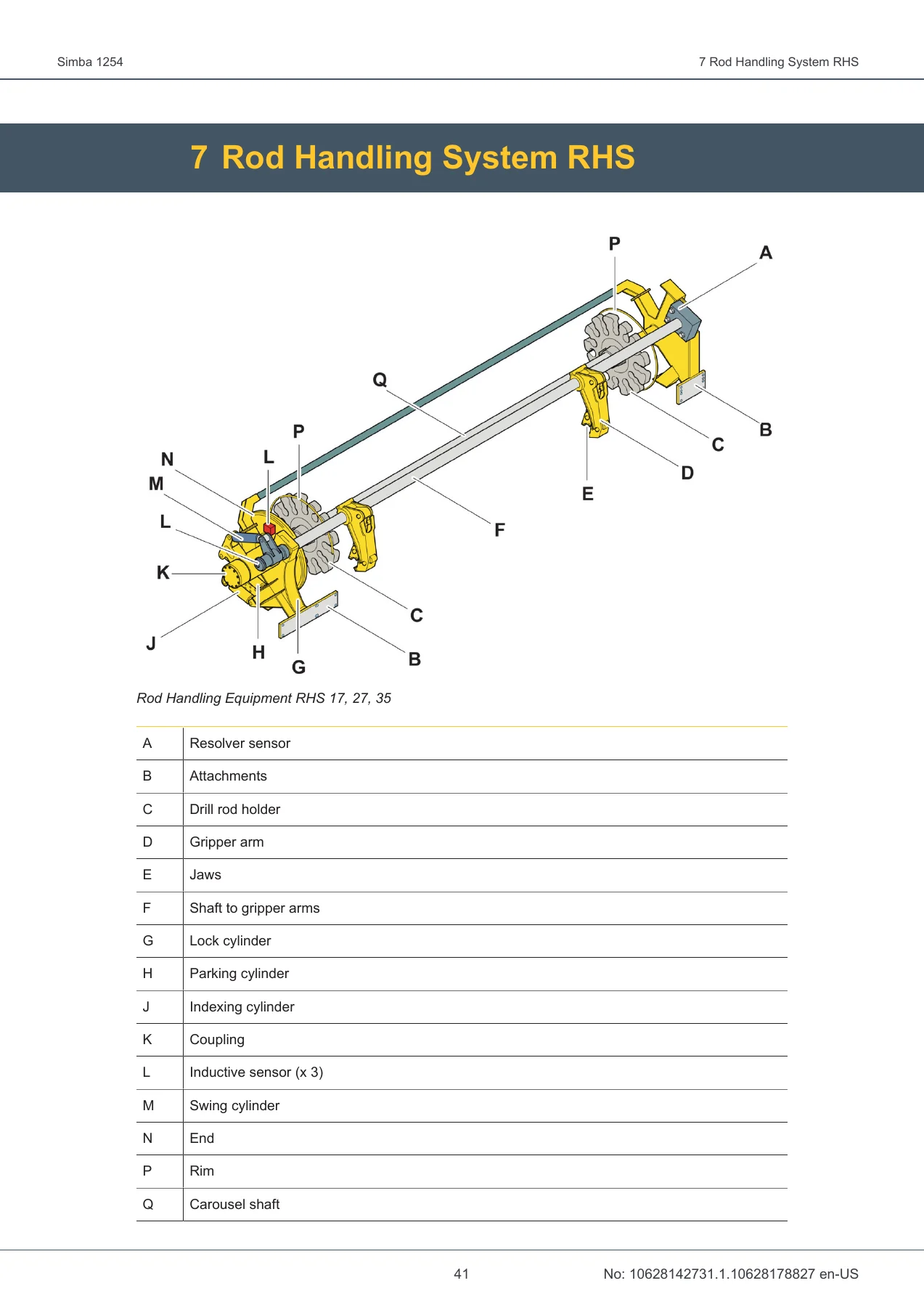
- 7. Rod Handling System RHS – Safety Precautions, Mechanical Adjustments, Indexing Cylinder Stroke, Parking Cylinder Eye, Drill Rod Position, Drill Rod Holder, Gripper Arm Jaws, Drill Rod Segment, Angle Contact Guide Bearings, Carousel Shaft Shimming, Axle Bearings, Tightening Torque, Bearing Points, Rod Handling Jaws, Gripper Arms Position, Park Position, Carousel, Carousel Indexing, RHS Lock Cylinder, Inductive Sensors, Electrical Components, Hydraulic Hoses, Lubrication
- 8. Positioning Equipment – Safety Precautions, Rotary Actuator Preparation, Tightening Torque, Cleaning, Lubrication
- 9. Hydraulic System – Safety Precautions, Technical Data, Working on Hydraulic Components, Hydraulic Workshops, Replacing Hydraulic Hoses, Checking Hoses and Couplings, Hydraulic Oil, Oil Sampling, Oil Levels, Draining Water Condensation, Emptying Tank, Filling Oil Manually, Hydraulic Filters, Breather Filter, Return Oil Filter, Suction Filter, Hydraulic Pumps, Power Unit Pumps Overview, Pump Rotation Direction, Starting New or Reconditioned Pump, Bleeding Pump, Circulating Pump, Basic Pump Setting, Settings, Pressure Settings and Rotation Speeds, Main Pump, Rotation Pump, Rock Drill Damper Pressure, Rod Coupling, Feed Pressure, Anti-jamming Protection, ECL Lubricating System Adjustment, Maximum Flow in Drill Feed Circuit, Pressure Regulators for Stingers and Feed Extension
- 10. Diesel Engine – Safety Precautions, Engine Overview, Technical Data, Fuel System (Replace Fuel Filter, Drain Pre-Filter, Replace Pre-Filter Insert, Venting Fuel System, Drain Water Condensation, Check Oil Leak), Air System (Check/Replace Air Filter, Safety Cartridge, Cleaning Dust Valve, Indicator Lamp), Oil System (Check Oil Level, Replace Engine Oil, Replace Oil Filter), Belts (Check Tension, Adjust Alternator Belt, Replace Alternator Belt), Alternator, Check Torque, Battery Connection, Engine Suspension, Pipe Connections, Lifting Engine Package, Engine Diagnostics
- 11. Cooling System – Safety Precautions, Clean Cooling System, Draining Coolant, Adding Coolant
- 12. Exhaust System – Replacing Catalytic Converter
- 13. Water System – Safety Precautions, Setting Water Flow Switch, Replacing Water Pump Shaft Seal, Clean Water Strainer, Draining Water System
- 14. Pneumatic System – Safety Precautions, Compressor Overview, Adjusting Unloading Pressure, Adjusting Loading Pressure, Adjusting Lubrication Air Pressure, Draining Condensation from Air Tank, Check Oil Level, Check Air Filter
- 15. Electrical System, IEC and Australia – Safety Precautions, Lighting Safety, Troubleshooting, Cable Marking, Component Marking, Low-Voltage Circuit, Extra Low-Voltage Circuit, Electrical Distribution Cabinet IEC/AUS (380-690 V and 1000 V), Voltmeter and Ammeter Overview, Checking Voltage/Current/Percussion Hours, Hour Counter, Electrical System Protection, Main Switch, Resetting Phase Sequence Alarm, Ground Fault Equipment, Motor Protection Relay Fanox, Relay Cabinet, Setting Time Relays
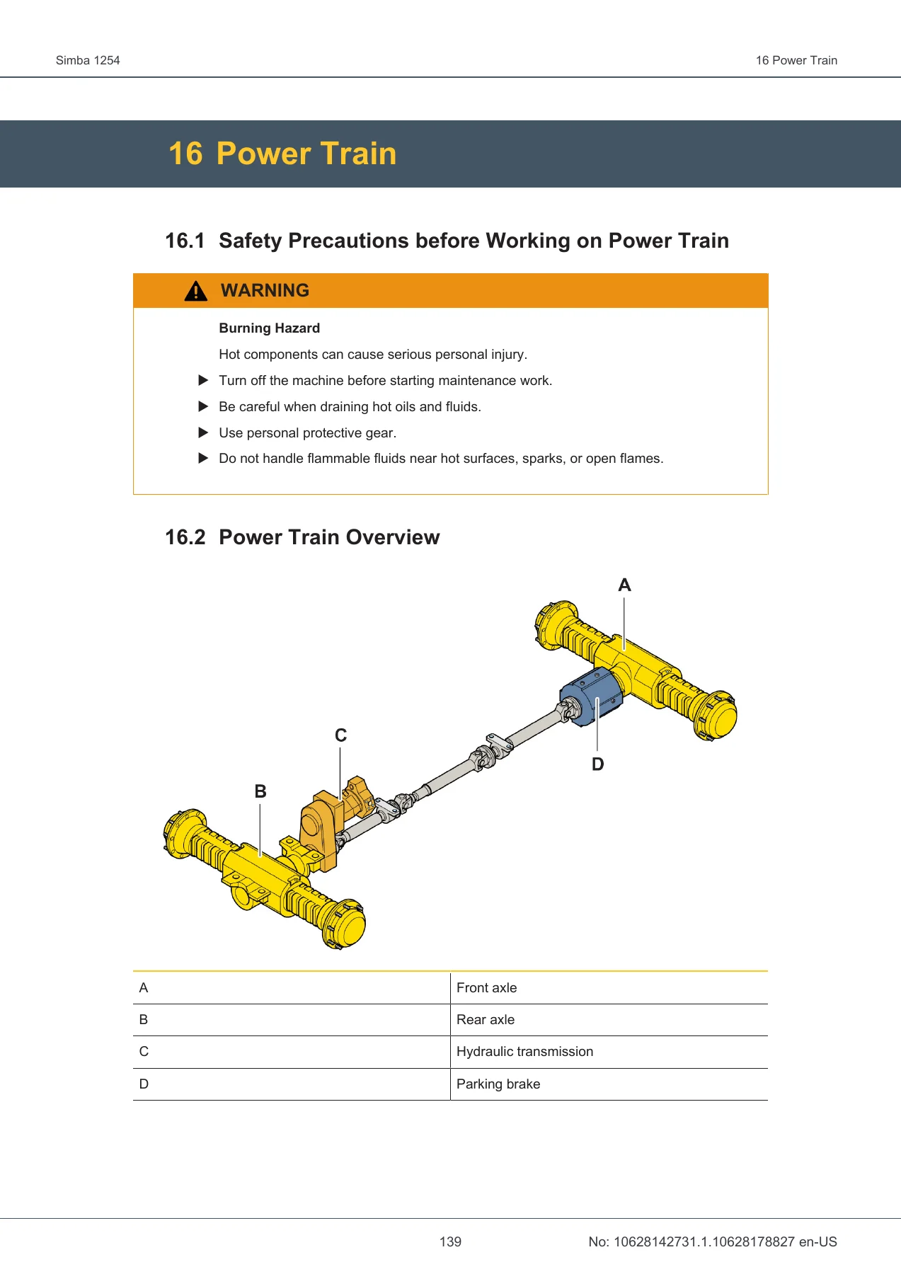
- 16. Power Train – Safety Precautions, Power Train Overview, Technical Data (Wheels, Steering, Drive Shafts, Transmission), Checking Tires and Rims, Steering System, Check Oil Level in Axle Differential, Check Oil Level in Planetary Gears, Check Tightening Torque on Wheel Bolts and Nuts, Check Oil Level in Transmission, Check Tire Pressure, Check Central Lubrication Hoses and Nipples, Check Spider Joints, Check Articulated Joint, Replace Oil in Axle Differential, Replace Oil in Planetary Gears, Replace Transmission Oil, Lubricate Cardan Shafts, Towing
- 17. Brake System – Safety Precautions, Technical Data, Check Service Brake, Check Service Brake Pressure, Check Parking Brake Pressure, Check Brake Discs, Check Parking Brake, Checking Accumulator Charge Pressure, Checking Brake Pressure Control Valve, Checking Accumulators, Replacing Accumulator, Bleeding the Service Brake and Parking Brake
- 18. Reeling Unit – Power Supply Cable, Reeling Unit RAC 612/RAC 614, Reeling Unit RAC 611, Adjust Drive Chain, Adjust Slip Clutch, Adjusting Limit Switch, Adjusting Speed, Check Oil Level in Gear, Check Cable Reeling Unit Collector, Check Hose Connections, Replace Oil in Gear, Lubricate Drive Chain and Bearings, Rotate Reeling Unit
- 19. Lubrication System – Automatic Central Lubrication System CLS, Power Supply, Circuit Diagram, Lubrication Pump Safety Valve, Lubrication Return Connection, Fill Lubricant, Test CLS, Setting Lubrication Pause and Running Time, Thread Lubrication
- 20. Component Locations – Hydraulic Controlled Valves, Pressure Gauge, Sensor, and Flow Switch, Modules and Sensors
- Maintenance Table – Calendar Time (Daily), Diesel Engine Hours (10, 50, 100, 250, 500, 1000, 2000)
This manual gives a technician a structured framework for every stage of the Simba 1254’s service life. The maintenance table alone is a complete planning tool – it maps each task to a specific interval, whether calendar-based or tied to diesel engine hours, so nothing gets skipped and no component runs past its service window. Beyond the schedule, the manual dives deep into the systems that define this drill rig: the Feeder 200-series with its cradle, slide pieces, and feed cylinder; the Rod Handling System with its carousel, gripper arms, and indexing adjustments; the hydraulic system with its pump settings, pressure regulators, and oil sampling routine; and the Deutz diesel engine with its fuel, air, oil, and belt maintenance. Brake system testing, power train oil changes, reeling unit upkeep, and the automatic central lubrication system all get dedicated chapters with step-by-step procedures, exploded illustrations, and the exact pressure or torque values a technician needs to work confidently.
Why This Manual Matters
Epiroc designed the Simba 1254 for production drilling, and the maintenance procedures in this document are what keep the machine in that role rather than parked for repairs. The hydraulic system alone relies on dozens of specific pressure settings – from the 200-220 bar percussion and positioning pressure down to the 16-20 bar stand-by pressure on the main pump, the 120 bar rotation pump setting, and the 30 bar back-pressure valve for drill rod support. Miss those numbers and you risk damaging the rock drill, the rod handling system, or the feed unit. The brake system chapter similarly calls for a service brake pressure of 80-85 bar, a parking brake pressure of 25 bar, and an accumulator charge pressure of at least 35 bar – all factory-set values that must be verified with a pressure gauge, not guessed. This Epiroc Simba 1254 maintenance manual puts those numbers in front of you before you open a valve or turn a screw.
The feed unit and rod handling system sections are equally critical for machine uptime. The manual explains how to adjust the cradle on the feed beam, replace worn slide pieces and slide rails, set the drill rod support pressure, and tune the RHS indexing cylinder stroke length. It also covers the less obvious maintenance work – lubricating the feeder grease nipples, checking the carousel indexing friction clutch, inspecting the reeling unit collector for carbon brush condition, and draining water condensation from the fuel tank. These are the tasks that separate a machine that runs reliably from one that suffers repeat failures.
Who This Manual Is For
This PDF is written for maintenance personnel, service technicians, and operators who are responsible for the upkeep of an Epiroc Simba 1254. The manual assumes basic familiarity with mining equipment and hydraulic systems, so it does not stop to explain what a pressure gauge or a torque wrench is – it goes straight to the procedure, the specification, and the safety precaution. If you are new to the machine, the component locations chapter and the system overview illustrations give you a solid starting point for understanding how the major assemblies relate to each other. If you have been working on drill rigs for years, the maintenance table and the detailed pressure settings are what you will reach for most often.
Complete PDF Bookmark Tree
Complete Bookmarks
The complete bookmarks in the “Epiroc Simba 1254 Maintenance Manual 2019 – PDF Workshop Guide” are as follows:
Table of Contentsp. 3
+1 Introductionp. 9
1.1 Safety Firstp. 9
1.2 The Purpose of This Publicationp. 9
1.3 Target Groupp. 9
1.4 Product Warrantyp. 9
+2 About Maintenance Managementp. 11
2.1 Maintenance Management and Hour Metersp. 11
2.2 Maintenance Recordsp. 11
2.3 Oil Analysisp. 11
+3 Specificationsp. 13
3.1 Standard Tightening Torques for Bolted Jointsp. 13
+4 General Machine Conditionp. 15
4.1 Wash Machine Externallyp. 15
4.2 Examine the Condition of Signsp. 15
4.3 Check Condition of Hatches and Locksp. 15
+5 Fire Fighting Equipmentp. 17
5.1 Check Fire Extinguishersp. 17
5.2 Loosen up Powder in Handheld Fire Extinguisherp. 17
5.3 Check Fire Fighting System Actuatorsp. 17
5.4 Check Fire Fighting Systemp. 18
+6 Feed Unitp. 21
6.1 Safety Precautions before Working on Feed Unitp. 21
6.2 Feeder 200-Seriesp. 21
6.3 Feeder 200 Series Technical Datap. 22
6.4 Check Cradle Hinge Playp. 22
6.5 Replace Rock Drill Retaining Boltsp. 23
+6.6 Installing Rock Drill and Rotation Unitp. 24
6.6.1 Safety Check after Rock Drill and Rotation Unit Installationp. 25
6.7 Check Slide Pieces on Feederp. 26
6.8 Check Tightening Torque on Feederp. 26
6.9 Adjusting Cradle on Feed Beamp. 26
6.10 Replacing Slide Pieces in the Holderp. 28
6.11 Replacing Slide Railsp. 29
6.12 Check Length Sensor on Feederp. 31
6.13 Check Electrical Components on Feederp. 31
6.14 Check Hydraulic Box on Feederp. 31
6.15 Check Hydraulic Hoses on Feederp. 31
6.16 Check Hydraulic Cylinder on Feederp. 31
6.17 Lubricate Feederp. 32
6.18 Disassembling Feed Cylinderp. 32
6.19 Assembling Feed Cylinderp. 34
+6.20 Drill Rod Supportp. 37
6.20.1 Overview of Drill Rod Supportp. 37
6.20.2 Check Tightening Torque on Drill Rod Supportp. 37
6.20.3 Check Drill Center of Drill Rod Supportp. 38
6.20.4 Check Drill Rod Support Jawsp. 38
6.20.5 Adjusting Drill Rod Support Cylinderp. 38
6.20.6 Adjusting Pressure for Drill Rod Supportp. 39
+7 Rod Handling System RHSp. 41
7.1 Safety Precautions before Working on RHSp. 42
+7.2 Mechanical Adjustmentsp. 42
7.2.1 Adjusting Stroke Length of Indexing Cylinderp. 42
7.2.2 Adjusting Cylinder Eye of Parking Cylinderp. 43
7.2.3 Adjusting Drill Rod Position in Drill Centerp. 43
7.2.4 Adjusting Drill Rod Holderp. 45
7.2.5 Replacing Gripper Arm Jawsp. 46
+7.2.6 Replacing Drill Rod Segmentp. 46
7.2.6.1 Gripper Arm Positionp. 47
7.2.7 Adjusting Play in Angle Contact Guide Bearings for Gripper Arm Shaftp. 48
7.2.8 Adjusting Play in Rear Angle Contact Guide Bearings on Carousel Shaftp. 49
7.2.9 Adjusting Carousel Shaft Shimming Bearingsp. 49
7.2.10 Adjusting Axle Bearingsp. 49
7.3 Check Tightening Torque RHSp. 49
7.4 Check Bearing Points of RHSp. 50
7.5 Check Rod Handling Jawsp. 50
7.6 Check Position of Gripper Armsp. 51
7.7 Check Gripper Arm Park Positionp. 51
7.8 Check Carouselp. 51
7.9 Check Carousel Indexingp. 51
7.10 Check RHS Lock Cylinderp. 52
7.11 Check Rod Handling Inductive Sensorsp. 52
7.12 Check Electrical Components of RHSp. 52
7.13 Check Hydraulic Hoses of RHSp. 53
7.14 Lubricate Rod Handlingp. 53
+8 Positioning Equipmentp. 55
8.1 Safety Precautions before Working on Positioning Equipmentp. 55
8.2 Preparations before Starting the New Rotary Actuatorp. 55
8.3 Check Tightening Torque on Rotary Actuatorp. 56
8.4 Clean Rotary Actuatorp. 56
8.5 Lubricate Rotary Actuatorp. 56
+9 Hydraulic Systemp. 57
9.1 Safety Precautions before Working on Hydraulic Systemp. 57
9.2 Technical Datap. 57
9.3 About Working on Hydraulic Componentsp. 57
9.4 Hydraulic Workshopsp. 58
9.5 Replacing Hydraulic Hosesp. 58
9.6 Check Hydraulic Hoses and Couplingsp. 59
+9.7 Hydraulic Oilp. 59
+9.7.1 Oil Samplingp. 59
9.7.1.1 Replacing Contaminated Oilp. 59
9.7.2 Check Oil Levelsp. 60
9.7.3 Drain Water Condensation from Hydraulic Oil Tankp. 60
9.7.4 Emptying Hydraulic Oil Tankp. 61
9.7.5 Filling Hydraulic Oil Manuallyp. 62
+9.8 Hydraulic Filtersp. 62
9.8.1 Check Hydraulic Tank Breather Filterp. 62
9.8.2 Replace Breather Filterp. 63
9.8.3 Replace Return Oil Filterp. 64
9.8.4 Replace Suction Filterp. 65
+9.9 Hydraulic Pumpsp. 65
9.9.1 Overview of Power Unit Pumpsp. 65
9.9.2 Checking Pump Rotation Directionp. 66
9.9.3 Starting New or Reconditioned Pumpp. 66
9.9.4 Bleeding Hydraulic Pumpp. 67
9.9.5 Circulating Hydraulic Pumpp. 67
+9.9.6 Basic Setting for the Pumpp. 69
9.9.6.1 Technical Datap. 69
9.9.6.2 Percussion Pump Control Valvep. 69
9.9.6.3 Rotation Pump Control Valvep. 70
+9.10 Settingsp. 70
9.10.1 Safety Precautions before Pressure Settingp. 70
9.10.2 Before Settingsp. 71
9.10.3 Overview of Hydraulic Panelp. 72
9.10.4 Pressure Settings and Rotation Speedsp. 72
+9.10.5 Main Pumpp. 74
9.10.5.1 Adjusting Stand-By Pressure for Main Pumpp. 74
9.10.5.2 Checking Stand-By Pressurep. 74
9.10.5.3 Adjusting Percussion and Positioning Pressurep. 75
9.10.5.4 Adjusting Maximum Pressure for Percussion Pumpp. 75
+9.10.6 Rotation Pumpp. 76
+9.10.6.1 Setting Rotation Speedp. 76
9.10.6.1.1 Adjusting Rotation Speed during Drillingp. 76
9.10.6.2 Setting Maximum Pressure and Stand-By Pressurep. 76
9.10.6.3 Adjusting Percussion Pressure for Collaring and Reduced Drillingp. 77
+9.10.7 Rock Drill Damper Pressurep. 78
9.10.7.1 Adjusting Pressure for Flow Regulatorp. 78
9.10.7.2 Adjusting Pressure Switch B132p. 78
9.10.7.3 Setting Pressure for Drill Rod Supportp. 78
+9.10.8 Rod Couplingp. 79
9.10.8.1 Adjusting Feed Speed for Threading and Unthreadingp. 79
9.10.8.2 Adjusting Maximum Rotation Pressure for Threadingp. 79
+9.10.9 Feed Pressurep. 80
9.10.9.1 Adjusting Feed Pressure for Collaringp. 80
9.10.9.2 Adjusting Feed Pressure for Full Drillingp. 80
9.10.9.3 Adjusting Reverse Feed Pressurep. 82
+9.10.9.4 Basic Settings for Feed Pressurep. 82
9.10.9.4.1 Before Basic Settingsp. 82
9.10.9.4.2 Basic Settingsp. 83
+9.10.10 Anti-jamming Protectionp. 84
9.10.10.1 Setting Anti-Jamming Protectionp. 84
+9.10.11 ECL Lubricating System Adjustmentp. 86
9.10.11.1 Metering Lubricating Oilp. 86
9.10.12 Setting Maximum Flow in Drill Feed Circuitp. 87
9.10.13 Adjusting Pressure Regulators for Stingers and Feed Extensionp. 87
+10 Diesel Enginep. 89
10.1 Safety Precautions before Working on Diesel Enginep. 89
10.2 Diesel Engine Overviewp. 89
10.3 Technical Datap. 90
+10.4 Fuel Systemp. 91
10.4.1 Replace Fuel Filterp. 91
10.4.2 Drain Pre-Filterp. 92
10.4.3 Replace Fuel Pre-Filter Insertp. 93
10.4.4 Venting Fuel Systemp. 94
10.4.5 Drain Water Condensation from Fuel Tankp. 94
10.4.6 Check Oil Leakp. 95
+10.5 Air Systemp. 95
10.5.1 Check Air Filterp. 95
10.5.2 Replace Air Filter Cartridgep. 95
10.5.3 Replace Air Filter Safety Cartridgep. 96
10.5.4 Cleaning Dust Valvep. 96
10.5.5 Check Air Filter Indicator Lamp Functionp. 97
+10.6 Oil Systemp. 98
10.6.1 Check Engine Oil Levelp. 98
10.6.2 Replace Engine Oilp. 99
10.6.3 Replace Engine Oil Filterp. 100
+10.7 Beltsp. 101
10.7.1 Check Belt Tensionp. 101
10.7.2 Adjust Alternator Beltp. 102
10.7.3 Replace Alternator Beltp. 102
10.8 Alternatorp. 103
10.9 Check Torquep. 103
10.10 Check Battery Connectionp. 103
10.11 Check Engine Suspensionp. 103
10.12 Check Pipe Connectionsp. 103
10.13 Lifting Engine Packagep. 104
10.14 Engine Diagnosticsp. 104
+11 Cooling Systemp. 105
11.1 Safety Precautions before Working on Cooling Systemp. 106
11.2 Clean Cooling Systemp. 107
11.3 Draining Coolantp. 108
11.4 Adding Coolantp. 109
+12 Exhaust Systemp. 111
12.1 Replacing Catalytic Converterp. 111
+13 Water Systemp. 113
13.1 Safety Precautions before Working on Water Systemp. 113
13.2 Setting Water Flow Switchp. 113
13.3 Replacing Water Pump Shaft Seal – Electric Drivep. 114
13.4 Clean Water Strainerp. 116
13.5 Draining Water Systemp. 116
+14 Pneumatic Systemp. 119
14.1 Safety Precautions before Working on Pneumatic Systemp. 119
14.2 Overview of Compressorp. 119
14.3 Adjusting Compressor Unloading Pressurep. 120
14.4 Adjusting Compressor Loading Pressurep. 120
14.5 Adjusting Lubrication Air Pressurep. 121
14.6 Draining Condensation from Air Tankp. 122
14.7 Check Oil Levelp. 122
14.8 Check Air Filterp. 122
+15 Electrical System, IEC and Australiap. 125
15.1 Safety Precautions before Working on Electrical Systemp. 125
15.2 Safety Precautions before Working on Lightingp. 125
15.3 Before Troubleshooting Electrical Systemp. 125
15.4 Cable Markingp. 126
15.5 Electrical Component Markingp. 126
15.6 Low-Voltage Circuitp. 126
15.7 Extra Low-Voltage Circuitp. 126
+15.8 Electrical Distribution Cabinetp. 127
15.8.1 Electrical Distribution Cabinet IEC, AUS (380–690 V)p. 127
15.8.2 Electrical Distribution Cabinet IEC, AUS (1000V)p. 128
15.8.3 Overview of Voltmeter and Ammeterp. 128
15.8.4 Checking Voltage, Current, and Percussion Running Hoursp. 129
15.8.5 Hour Counterp. 129
+15.9 Electrical System Protectionp. 130
15.9.1 Main Switchp. 130
15.9.2 Resetting Phase Sequence Alarmp. 130
15.9.3 Ground Fault Equipmentp. 131
+15.10 Motor Protection Relay Fanoxp. 131
15.10.1 Overview of Electronic Motor Protection Relayp. 132
15.10.2 Checking if Motor Protection is Triggeredp. 133
15.10.3 Checking if Motor Protection Is Triggered (for 360–690 V)p. 133
15.10.4 Setting Rated Currentp. 134
15.10.5 Fuses for Carrierp. 134
+15.11 Relay Cabinetp. 135
15.11.1 Overview of Relay Cabinetp. 135
+15.11.2 Setting Time Relaysp. 136
15.11.2.1 Setting Time Relay K113p. 137
15.11.2.2 Setting Time Relay K114p. 138
+16 Power Trainp. 139
16.1 Safety Precautions before Working on Power Trainp. 139
16.2 Power Train Overviewp. 139
+16.3 Technical Datap. 140
16.3.1 Wheelsp. 140
16.3.2 Steeringp. 140
16.3.3 Drive Shaftsp. 140
16.3.4 Transmissionp. 140
16.4 Checking Tires and Rimsp. 141
16.5 Steering Systemp. 142
16.6 Check Oil Level in the Axle Differentialp. 142
16.7 Check Oil Level in Planetary Gearsp. 143
16.8 Check Tightening Torque on Wheel Bolts and Nutsp. 143
16.9 Check Oil Level in the Transmissionp. 144
16.10 Check Tire Pressurep. 144
16.11 Check Central Lubrication Hoses and Nipplesp. 145
16.12 Check Spider Jointsp. 145
16.13 Check Articulated Jointp. 145
16.14 Replace Oil in the Axle Differentialp. 146
16.15 Replace Oil in Planetary Gearsp. 146
16.16 Replace Transmission Oilp. 147
16.17 Lubricate Cardan Shaftsp. 148
+16.18 Towingp. 149
16.18.1 Safety Precautions Before Towingp. 149
16.18.2 Disengaging the Parking Brakep. 150
16.18.3 Removing Cardan Shaftsp. 150
16.18.4 Disconnecting Steering Cylinderp. 151
+16.18.5 Restoring After Towingp. 151
16.18.5.1 Adjusting the Parking Brakep. 152
+17 Brake Systemp. 153
17.1 Safety Precautions before Working on Brake Systemp. 153
17.2 Technical Datap. 153
17.3 Check Service Brakep. 153
17.4 Check Service Brake Pressurep. 154
17.5 Check Parking Brake Pressurep. 155
17.6 Check Brake Discsp. 155
17.7 Check Parking Brakep. 156
17.8 Checking Accumulator Charge Pressurep. 157
17.9 Checking Brake Pressure Control Valvep. 158
17.10 Checking Accumulatorsp. 158
17.11 Replacing Accumulatorp. 160
17.12 Bleeding the Service Brake and Parking Brakep. 161
+18 Reeling Unitp. 163
18.1 Power Supply Cablep. 163
18.2 Reeling Unit RAC 612/RAC 614p. 164
18.3 Reeling Unit RAC 611p. 164
18.4 Adjust Reeling Unit Drive Chainp. 165
18.5 Adjust Reeling Unit Slip Clutchp. 165
18.6 Adjusting Limit Switchp. 166
18.7 Adjusting Reeling Unit Speedp. 167
18.8 Check Oil Level in Reeling Unit Gearp. 167
18.9 Check Cable Reeling Unit Collectorp. 167
18.10 Check Hose Connectionsp. 168
18.11 Replace Oil in Reeling Unit Gearp. 169
18.12 Lubricate Drive Chain and Bearingsp. 169
18.13 Rotate Reeling Unitp. 169
+19 Lubrication Systemp. 171
+19.1 Automatic Central Lubrication System CLSp. 171
19.1.1 Central Lubrication Systemp. 171
19.1.2 Central Lubrication System Power Supplyp. 172
19.1.3 Central Lubrication System Circuit Diagramp. 173
19.1.4 Lubrication Pump Safety Valvep. 174
19.1.5 Lubrication Return Connectionp. 174
19.1.6 Fill Lubricantp. 175
19.1.7 Test Central Lubrication Systemp. 176
19.1.8 Setting Lubrication Pause and Running Timep. 176
19.2 Thread Lubricationp. 177
+20 Component Locationsp. 179
20.1 Hydraulic Controlled Valvesp. 179
20.2 Pressure Gauge, Sensor, and Flow Switchp. 180
20.3 Modules and Sensorsp. 180
Maintenance tablep. 183
Get It Instantly
This Epiroc Simba 1254 maintenance manual is delivered as an instant PDF download – no shipping, no waiting, no physical book to keep track of in a workshop. You can open it on a laptop, tablet, or smartphone, print the pages you need for a particular job, and keep the full 188-page document on hand for reference. Whether you are performing a daily walkaround, a 500-hour service, or a full hydraulic pressure adjustment, the procedures and specifications are organized to let you find what you need quickly and get the machine back to work.



Reviews
There are no reviews yet.