Description
Sandvik DS411-C Operator’s Manual — BG00418083
The complete operator’s manual for the Sandvik DS411-C rock reinforcement drill rig, published by Sandvik Mining and Construction Oy. This 376-page PDF (document number BG00418083, edition D.001.1, dated 2016-10-10) is the full English-language operator’s manual that ships with the DS411-C bolting rig, covering everything from start-up and tramming through rock drilling, bolting with cement, resin, Kiruna, Split Set and Swellex bolts, daily operator maintenance, towing, transport, lifting, storage, and troubleshooting.
File Details
- Manual type: Operator’s Manual
- Brand: Sandvik
- Model: DS411-C
- Manufacturer: Sandvik Mining and Construction Oy, Tampere, Finland
- Language: English
- Page count: 376 pages
- File format: PDF
- Document number: BG00418083
- Edition / revision: en-US D.001.1
- Publication date: 2016-10-10
Chapters Covered
- 1. Introduction — purpose of the instructions, product identification, serial number location, manual identification, definitions
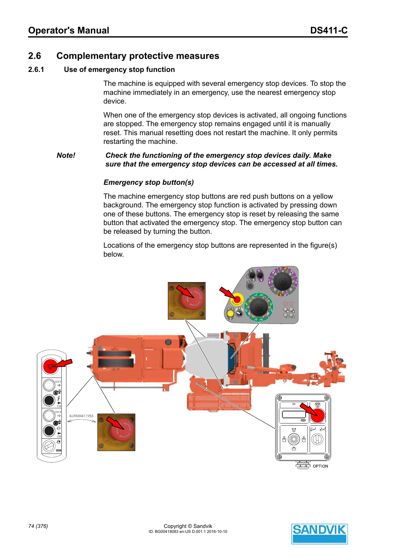
- 2. Safety and environmental instructions — signal words and symbols, safety labels and their locations, user obligations, PPE, intended and prohibited use, centre of gravity, maximum inclination angles, operator visibility, hazard zones, guards and protective devices, emergency stop function, emergency exits, isolation and energy dissipation, fire risk control, fire suppression systems (ANSUL and FS1000), emission hazards (noise, vibration, dust), emergency procedures, decommissioning and disposal, incident reporting
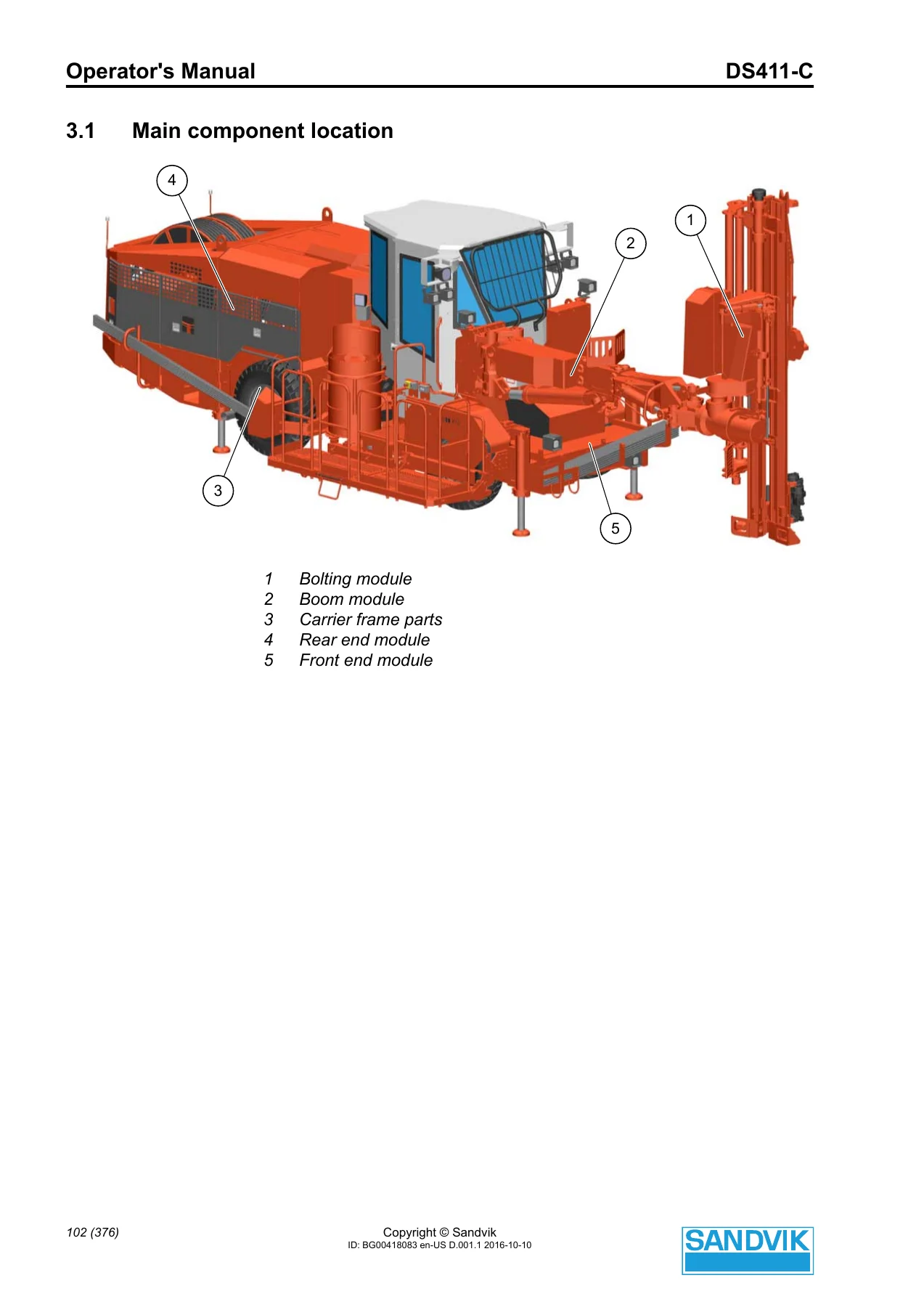
- 3. Machine description — main component location, bolting module, boom module, carrier frame parts, rear end module, front end module, utility boom module, machine orientation, description of controls and functions, tramming panel (DP), switch panel (SW), indicator panel (QN), side panels, wipers, cooling and heating controls, remote control for reels (ERCP), hydraulic oil filling switch, high pressure washer switch, cement mixer control panel, bolt cassette rotation control panel, reversing camera monitor, power pack control panel (MCP), utility boom control panels, drilling and bolting panels, bolting instrument (user interface, hardware, main screen, screen map, navigation, data transfer, round status, diagnostics, calibration, system preferences), main fuses and circuit breakers for 380–690 V, 1000 V and MSC/MSU switchgear
- 4. Operating instructions — starting procedure (diesel engine), shutdown procedure, tramming controls (before tramming, tramming position, speed range selection, steering, braking, parking, positioning at the drilling site, tramming between drilling sites), utility boom controls, drilling and bolting controls (safety instructions, principles of percussion drilling, drill steel, power pack start/stop, water pump and compressor, filling the bolt cassette, starting the bolting instrument, data transfer via USB, reference bolting, drilling and bolting with cement, resin, Kiruna, Split Set and Swellex bolts, drilling parameters, during drilling, after drilling, special situations, ending a shift), TMS display, cabin accessories, operation prevention functions
- 5. Operator’s maintenance instructions — daily checks and tasks for hydraulic rock drill RD314, boom TBR60, SUBi utility boom, hydraulic bolting head, chain feed KS140, carrier (tires, transmission, hydraulic oil), diesel engine MB, cable and water hose reel, cement system, drilling hydraulics, water circuit, air circuit, compressor CTN and CT, SLU, electric system, safety cabin and other components
- 6. Additional instructions — towing (with and without operational brakes, releasing parking brakes), transport, lifting, reassembling with removed parts after transport, storage, washing
- 7. Troubleshooting — operator-level troubleshooting instructions for the diesel engine and power pack, plus utility boom fault flash codes
Across its 376 pages, the manual gives the DS411-C operator a complete working reference: how the bolting module, boom, carrier frame, rear end module and front end module are laid out; where every control, gauge and indicator lives; how the bolting instrument’s touchscreen is used for reference bolting, systematic bolting, diagnostics and calibration; and what safety measures must be in place before any drilling or tramming begins. The safety section alone runs roughly 80 pages and documents the machine’s specific hazard zones, guard locations, emergency stop button placement, fire suppression options and mandatory PPE.
What This Manual Enables You to Do
This is not a general mining reference — it is the exact book an operator needs beside the DS411-C to run a shift safely and correctly. Use it to:
- Run the full start-up sequence on the MB 904 LA or Cummins diesel engine and confirm that all gauges and indicator lights read within normal ranges before moving the machine
- Carry out the brake test exactly as the manufacturer specifies, before every shift
- Tram the rig safely: speed range selection, steering, braking, parking on level and inclined ground, and positioning at the drilling face within the machine’s maximum inclination angles
- Drill and bolt with all supported bolt types — cement, resin, Kiruna, Split Set and Swellex — following the step-by-step joystick procedures
- Set up and navigate with the bolting instrument’s touchscreen, including reference bolting with the fan laser, continuing an unfinished fan, editing hole properties, and transferring data via USB
- Operate the optional utility boom from the operator station, from the basket, or directly from the valves in an emergency
- Perform the daily operator maintenance routine: rock drill leak checks, flushing housing seals, boom hoses and cables, chain feed centralizers, tire pressure and torque values, transmission oil level, engine oil and coolant, water circuit mud separator, compressor oil level, SLU oil level and electrical system checks
- Troubleshoot common problems with the diesel engine, power pack and utility boom without waiting for service
- Tow, transport, lift, store and wash the rig safely, and understand the correct reassembly procedures after transport
Why Correct Procedures Matter on the DS411-C
The DS411-C is a rock reinforcement rig — the operator is almost always working close to a charged face, at the end of a tunnel, under unsupported rock. The manual’s safety content reflects that: hazard zones extend 5 metres on every side of the rig during tramming and setting up, the front area becomes a hazard zone during drilling, and any part of the drilling face that is charged makes drilling absolutely forbidden. The operator’s manual spells out where every emergency stop button sits, how to isolate the hydraulic, air, fuel and electrical systems before maintenance, how the ANSUL and FS1000 fire suppression systems are actuated, and what to do if the rig contacts a live power line. These are not generic warnings — they are the specific procedures the manufacturer expects the operator to know by heart.
The same applies to the technical side. The manual lists the correct drilling parameters (percussion, feed, rotation and flushing pressures), what symptoms indicate too much or too little feed force, when a drill bit must be replaced, and how to free a jammed rod. It gives the exact tire pressures and wheel nut torques for the DS411/DS421 on the NC7 carrier. And it documents the automatic stop functions that shut the diesel engine, power pack, compressor or water pump down if oil pressure, oil level, coolant temperature or hydraulic oil temperature drift out of range.
Complete PDF Bookmark Tree
Complete Bookmarks
The complete bookmarks in the “Sandvik DS411-C Operator's Manual – Rock Reinforcement Drill Rig PDF – BG00418083” are as follows:
+Operator's Manualp. 1
Table of Contentsp. 5
+1 Introductionp. 13
1.1 The purpose of these instructionsp. 14
+1.2 Identification of the productp. 15
1.2.1 Product type and serial numberp. 15
1.2.2 Product manufacturerp. 16
1.2.3 Manualsp. 17
1.2.4 How to identify the correct manual for the productp. 18
1.2.5 Validity of the manualsp. 18
1.3 Copyright noticep. 18
1.4 Definitionsp. 18
+2 Safety and environmental instructionsp. 21
+2.1 Safety labels, safety messages and signalsp. 22
2.1.1 Signal wordsp. 22
2.1.2 General hazard symbolp. 22
2.1.3 Mandatory action symbolsp. 23
2.1.4 Prohibited action symbolsp. 24
2.1.5 Hazard symbolsp. 25
2.1.6 Labels on the productp. 27
2.1.7 Visual and audible signalsp. 50
+2.2 User obligationsp. 51
2.2.1 Managing work related hazardsp. 52
2.2.2 Scheduled safety inspections and preventive maintenancep. 52
2.2.3 Personal protective equipmentp. 53
+2.3 Product limitationsp. 54
2.3.1 Intended usep. 54
2.3.2 Prohibited usep. 55
2.3.3 Center of gravityp. 56
2.3.4 Maximum inclination anglesp. 57
2.3.5 Operator visibilityp. 59
2.3.6 Modificationsp. 61
2.4 Hazard zonesp. 62
+2.5 Safeguardingp. 64
2.5.1 Guardsp. 64
2.5.2 Location of the guardsp. 65
2.5.3 Protective devicesp. 69
+2.6 Complementary protective measuresp. 74
2.6.1 Use of emergency stop functionp. 74
2.6.2 Emergency exitp. 75
2.6.3 Safe access to machine and three-point supportp. 75
2.6.4 Isolation and energy dissipationp. 76
+2.7 Fire risk control measuresp. 79
2.7.1 In case of firep. 80
2.7.2 Fire preventionp. 81
2.7.3 Fire retardant and flammable materialsp. 81
2.7.4 Fire suppressionp. 82
2.7.5 After a firep. 89
+2.8 Protection against emission hazardsp. 89
2.8.1 Noisep. 89
2.8.2 Vibrationp. 90
2.8.3 Dustp. 90
2.9 Emergency proceduresp. 90
+2.10 Safety considerations for maintenancep. 93
2.10.1 Daily inspections and tasks for operatorsp. 93
2.10.2 Tasks which require definite technical skills and maintenance trainingp. 94
+2.11 Environmentp. 94
2.11.1 Decommissioningp. 95
2.11.2 Dismantlingp. 96
2.11.3 Disposalp. 98
2.12 Potential product related hazards identified by the userp. 99
2.13 Incident reportingp. 100
+3 Machine descriptionp. 101
+3.1 Main component locationp. 102
3.1.1 Bolting modulep. 103
3.1.2 Boom modulep. 106
3.1.3 Carrier frame partsp. 107
3.1.4 Rear end modulep. 117
3.1.5 Front end modulep. 128
3.1.6 Utility boom module (optional)p. 133
3.1.7 Option modulep. 133
3.2 Machine orientationp. 136
+3.3 Description of controls and functionsp. 137
3.3.1 Tramming controlsp. 138
3.3.2 Tramming panel (DP)p. 138
3.3.3 Switch panel (SW) (cabin model)p. 158
3.3.4 Indicator panel (QN)p. 160
3.3.5 Side panelsp. 164
3.3.6 Wipersp. 165
3.3.7 Control devices for cooling and heatingp. 166
3.3.8 Remote control for reel(s) (ERCP)p. 167
3.3.9 Hydraulic oil filling (and vacuum) on/off switchp. 168
3.3.10 High pressure washer on/off switch (optional)p. 168
3.3.11 Cement mixer control panelp. 169
3.3.12 Cement hose feed control buttonp. 170
3.3.13 Bolt cassette rotation control panelp. 170
3.3.14 Reversing camera monitor (optional)p. 171
3.3.15 Power pack control panel (MCP)p. 172
3.3.16 Utility boom control panel (in the operator station)p. 173
3.3.17 Utility boom control panel (in the basket)p. 174
3.3.18 Drilling and bolting panelsp. 175
+3.4 Bolting instrumentp. 187
3.4.1 User interface controlp. 187
3.4.2 Hardware structurep. 189
3.4.3 Main screenp. 190
3.4.4 Screen mapp. 201
3.4.5 Recognizing a hole as drilled and recognizing a bolt as installedp. 202
3.4.6 Create a new bolting scenariop. 204
3.4.7 Navigation screenp. 205
3.4.8 Data transfer screenp. 208
3.4.9 Round Status screenp. 209
3.4.10 Diagnostics screensp. 210
3.4.11 Calibrationp. 217
3.4.12 System preferencesp. 218
+3.5 Main fuses and circuit breakers (380-690 V)p. 224
3.5.1 Switchesp. 225
3.5.2 Gaugesp. 225
3.5.3 Circuit breakersp. 226
+3.6 Main fuses and circuit breakers (1000 V)p. 227
3.6.1 Switchesp. 228
3.6.2 Gaugesp. 228
3.6.3 Circuit breakersp. 229
+3.7 Main fuses and circuit breakers (MSC/MSU)p. 230
3.7.1 Switchesp. 231
3.7.2 Gaugesp. 231
3.7.3 Circuit breakersp. 232
+4 Operating instructionsp. 233
+4.1 Starting procedurep. 234
4.1.1 Starting the diesel enginep. 234
4.1.2 When the diesel engine is runningp. 236
+4.2 Shut down procedurep. 237
4.2.1 Stopping the diesel enginep. 237
+4.3 Using tramming controlsp. 237
4.3.1 Before trammingp. 237
4.3.2 Tramming positionp. 239
4.3.3 Selecting the speed range and driving directionp. 240
4.3.4 Steeringp. 241
4.3.5 Brakingp. 242
4.3.6 Setting the rig in motionp. 243
4.3.7 Parkingp. 244
4.3.8 Positioning at the drilling sitep. 245
4.3.9 Tramming between drilling sitesp. 246
+4.4 Using utility boom controls (optional)p. 247
4.4.1 Safety instructionsp. 247
4.4.2 Preparations for moving the utility boomp. 248
4.4.3 Controlling the utility boom from the operator stationp. 249
4.4.4 Controlling the utility boom from the basketp. 250
4.4.5 Controlling the utility boom directly from valvesp. 253
4.4.6 Emergency situation with utility boomp. 254
4.4.7 Working at extreme conditionsp. 254
+4.5 Using drilling and bolting controlsp. 255
4.5.1 Safety instructionsp. 255
4.5.2 Principles of percussion drillingp. 257
4.5.3 Drill steelp. 262
4.5.4 Before starting the power packp. 263
4.5.5 Starting and stopping the power packp. 264
4.5.6 Starting the water pump and compressorp. 264
4.5.7 Before starting to drillp. 265
4.5.8 Filling the bolt cassettep. 266
4.5.9 Starting the bolting instrumentp. 267
4.5.10 Data transfer using USBp. 268
4.5.11 Reference boltingp. 269
4.5.12 Reference bolting functionalityp. 273
4.5.13 Bolting scenario editing functionsp. 281
4.5.14 Drilling, all bolt typesp. 283
4.5.15 Bolting with cementp. 283
4.5.16 Bolting with resinp. 289
4.5.17 Bolting with Kiruna boltsp. 291
4.5.18 Bolting with Split Set boltsp. 291
4.5.19 Bolting with Swellex boltsp. 292
4.5.20 Drilling parametersp. 293
4.5.21 During drillingp. 295
4.5.22 After drillingp. 296
4.5.23 Special situationsp. 297
4.5.24 Ending a shiftp. 299
4.6 Using TMS-display (optional)p. 300
+4.7 Using cabin accessoriesp. 304
4.7.1 Air conditioningp. 304
+4.8 Operation prevention functionsp. 306
4.8.1 Automatic stop functionsp. 306
4.8.2 Manual preventionp. 307
4.8.3 Automatic activation of the parking brakep. 307
+5 Operator's maintenance instructionsp. 309
5.1 Daily checksp. 310
+5.2 Generalp. 313
5.2.1 Checking the function of the hornp. 313
5.2.2 Checking the function of the working and driving lightsp. 313
5.2.3 Checking the function of gaugesp. 314
5.2.4 Checking the condition of the devices visuallyp. 314
5.2.5 Washing the drilling module and the front part of the machinep. 314
5.2.6 Checking the condition of the fire extinguisher(s) (optional)p. 314
5.2.7 Checking the condition of the access waysp. 314
+5.3 Hydraulic rock drill RD314p. 314
5.3.1 Checking the percussion hour-meter readingp. 314
5.3.2 Checking the possible leaksp. 314
5.3.3 Checking the flushing housing sealsp. 315
+5.4 Boom TBR60p. 316
5.4.1 Checking the zoom tube wiperp. 316
5.4.2 Washing the boomp. 316
5.4.3 Checking the condition of hoses and connectionsp. 316
5.4.4 Checking the condition of electrical cablesp. 316
+5.5 SUBi utility boomp. 316
5.5.1 Visual inspection of the hydraulic hoses, couplings and the boomp. 316
5.5.2 Checking all joint pinsp. 317
5.5.3 Inspecting the condition of the basketp. 317
5.5.4 Inspecting the boom attachment to the mounting bracketp. 318
+5.6 Hydraulic bolting headp. 319
5.6.1 Lubricating the greasing pointsp. 319
+5.7 Chain feed KS140p. 319
5.7.1 Checking the feed beamp. 319
5.7.2 Washing the feedp. 319
5.7.3 Checking the centralizer bushingsp. 320
5.7.4 Checking the condition of wear piecesp. 320
+5.8 Carrierp. 321
5.8.1 Checking the tire condition, pressure and nut tightnessp. 321
5.8.2 Checking the transmission oil levelp. 326
5.8.3 Checking the hydraulic oil levelp. 327
+5.9 Diesel engine MBp. 328
5.9.1 Cleaning the coarse filterp. 328
5.9.2 Checking the fuel level and filling the tankp. 329
5.9.3 Emptying the fuel water separatorp. 331
5.9.4 Checking the engine oil levelp. 332
5.9.5 Checking the coolant levelp. 333
+5.10 Cable and water hose reelp. 334
5.10.1 Checking the condition of the cable reelp. 334
5.10.2 Checking the condition of the water hose reelp. 334
+5.11 Cement systemp. 334
5.11.1 Lubricating cement mixer greasing pointsp. 334
+5.12 Drilling hydraulicsp. 335
5.12.1 Checking the hydraulic oil levelp. 335
5.12.2 Checking the pressure filterp. 336
5.12.3 Visually checking the condition of the hydraulic systemp. 336
+5.13 Water circuitp. 336
5.13.1 Checking the water circuit for leaksp. 336
5.13.2 Cleaning the mud separatorp. 337
5.13.3 Checking the operation of the pressure reducing valvep. 338
5.13.4 Venting and filling of water booster pumpp. 339
5.13.5 Checking the operation of the oil coolerp. 339
+5.14 Air circuitp. 340
5.14.1 Draining the air cleanerp. 340
5.14.2 Draining the air receivers (optional)p. 340
+5.15 Compressor CTNp. 340
5.15.1 Checking the correct running temperaturep. 340
5.15.2 Checking the cooling air fanp. 341
5.15.3 Checking the compressor oil levelp. 341
5.15.4 Checking for oil leaksp. 341
5.15.5 Cleaning the compressor air filter pre-cleanerp. 341
+5.16 Compressor CTp. 342
5.16.1 Checking the correct running temperaturep. 342
5.16.2 Checking the cooling air fanp. 342
5.16.3 Checking the compressor oil levelp. 342
5.16.4 Checking for oil leaksp. 342
5.16.5 Cleaning the compressor air filter pre-cleanerp. 343
+5.17 SLUp. 343
5.17.1 Checking the oil levelp. 343
+5.18 Electric systemp. 344
5.18.1 Electric system – Operator's safety instructionsp. 344
5.18.2 Checking the operation of the emergency stop devicesp. 346
5.18.3 Checking the electric cabinets and connection boxesp. 346
5.18.4 Checking the electric cables and harnessesp. 346
5.18.5 Checking the sockets and plugsp. 347
5.18.6 Checking the operation of the drilling module movement prevention switches (if equipped)p. 348
+5.19 Safety cabinp. 349
5.19.1 Checking the door locksp. 349
5.19.2 Checking the windowsp. 349
5.19.3 Checking the door gas springsp. 349
+5.20 Other componentsp. 350
5.20.1 Checking the grease level in the reservoirp. 350
+6 Additional instructionsp. 353
+6.1 Towingp. 354
6.1.1 Preparing for towingp. 354
6.1.2 Towing pointsp. 355
6.1.3 Towing the rig with brakes in operational conditionp. 355
6.1.4 Towing the rig without brakes in operational conditionp. 356
6.1.5 Releasing the parking brakesp. 357
6.1.6 After towingp. 357
6.2 Transportp. 359
6.3 Liftingp. 360
+6.4 Reassembling with the removed parts after transportationp. 362
6.4.1 Installing the drilling boomsp. 363
6.4.2 Installing the utility boomp. 364
6.4.3 Utility boom reassembly check-upp. 365
6.5 Storagep. 367
6.6 Washingp. 369
+7 Troubleshootingp. 371
7.1 Troubleshooting instructions for the operatorp. 372
7.2 Utility boom troubleshootingp. 373
Instant PDF Delivery — Your Complete DS411-C Reference
From the first brake test of the shift to the moment the rig is parked and the battery isolation switch is turned off, this Sandvik DS411-C Operator’s Manual covers the whole working day of a rock reinforcement rig. It puts the correct start-up sequence, drilling parameters, bolting procedures for every supported bolt type, daily maintenance routine, and operator-level troubleshooting in one place — so the operator runs the machine the way Sandvik designed it to be run, not by guesswork. Delivered as an instant PDF download, no shipping and no waiting: open it on any device, print the pages you need, and keep the whole 376-page manual on hand wherever the rig goes.


Reviews
There are no reviews yet.