Trusted Business
Verified & Licensed
Virus Free Files
100% Safe Downloads
Secure Payment
SSL Protected
Instant Delivery
Available Immediately
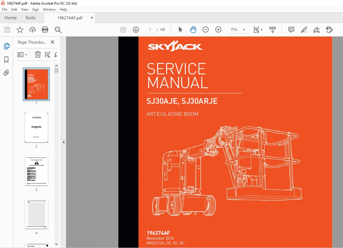
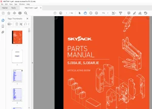
Skyjack SJ30AJE, SJ30ARJE Articulating Boom Service Manual 196274AF – PDF DOWNLOAD
$28.95
Skyjack SJ30AJE, SJ30ARJE Articulating Boom Service Manual 196274AF – PDF DOWNLOAD
SJ30AJE& SJ30ARJE: 90 000 001 to 90 999 999
Instant PDF Download
Available immediately
Save to Your Device
Download & keep forever
Antivirus Scanned
100% virus-free
Trusted Worldwide
175,000+ customers
Description
Skyjack SJ30AJE, SJ30ARJE Articulating Boom Service Manual 196274AF – PDF DOWNLOAD
FILE DETAILS:
Skyjack SJ30AJE, SJ30ARJE Articulating Boom Service Manual 196274AF – PDF DOWNLOAD
Language : English
Pages : 190
Downloadable : Yes
File Type : PDF
IMAGES PREVIEW OF THE MANUAL:
DESCRIPTION:
Skyjack SJ30AJE, SJ30ARJE Articulating Boom Service Manual 196274AF – PDF DOWNLOAD
SJ30AJE& SJ30ARJE: 90 000 001 to 90 999 999
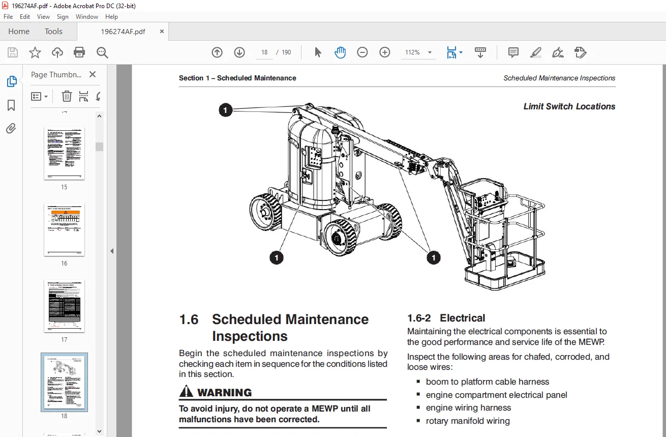
Scheduled Maintenance:
1.1 Read and Heed:
Skyjack is continuously improving and expanding product features on its equipment, therefore,
specifications and dimensions are subject to change without notice.
1.1 Read and Heed:
Skyjack is continuously improving and expanding product features on its equipment, therefore,
specifications and dimensions are subject to change without notice.
1.1-1 Mobile Elevating Work Platform (MEWP) Definition
A mobile device that has a positionable platform supported from ground level by a structure.
A mobile device that has a positionable platform supported from ground level by a structure.
1.1-2 Purpose of Equipment
The Skyjack Electric Articulating Boom Series MEWPs are designed to transport and raise personnel,
tools and materials to overhead work areas.
The Skyjack Electric Articulating Boom Series MEWPs are designed to transport and raise personnel,
tools and materials to overhead work areas.
1.1-3 Use of Equipment
The MEWP is a highly maneuverable, mobile work station. Work platform elevation and elevated
driving must only be done on a firm, level surface.
The MEWP is a highly maneuverable, mobile work station. Work platform elevation and elevated
driving must only be done on a firm, level surface.
1.1-4 Manual
Operating Manual: The operating manual is considered a fundamental part of the MEWP. It is a very
important way to communicate necessary safety information to users and operators. A complete
and legible copy of this manual must be kept in the provided weather-resistant storage compartment
on the MEWP at all times.
Service & Maintenance: The purpose of this is to provide the customer with the servicing and
maintenance procedures essential for the promotion of proper machine operation for its intended
purpose.
All information in this manual should be read and understood before any attempt is made to service
the machine.
1.1-5 Service Policy and Warranty
Skyjack warrants each new product to be free of defective parts and workmanship for the first 2
years or 3000 hours, whichever occurs first. Any defective part will be replaced or repaired by
your local Skyjackdealer at no charge for parts or labor.
In addition, all products have a 5 year structural warranty. Contact the Skyjack Service Department
for warranty statement extensions or exclusions.
1.1-6 Operator Safety Reminders, Warnings and Precautions
Operator safety is Skyjack’s priority. The operator should comply with all applicable
safety-related reminders, warnings and precautions found in the Operating Manual. They should be
read and understood completely before operating the MEWP.
Operator safety is Skyjack’s priority. The operator should comply with all applicable
safety-related reminders, warnings and precautions found in the Operating Manual. They should be
read and understood completely before operating the MEWP.
TABLE OF CONTENTS:
Skyjack SJ30AJE, SJ30ARJE Articulating Boom Service Manual 196274AF – PDF DOWNLOAD
Table of Contents.......................................................................  5
Section 1 – Scheduled Maintenance....................................................... 11
	1.1  Read and Heed.................................................................. 11
		1.1-1 Mobile Elevating Work Platform (MEWP) Definition.......................... 11
		1.1-2 Purpose of Equipment...................................................... 11
		1.1-3 Use of Equipment.......................................................... 11
		1.1-4 Manual.................................................................... 11
		1.1-5 Service Policy and Warranty............................................... 11
		1.1-6 Operator Safety Reminders, Warnings and Precautions....................... 11
	1.2  Maintenance and Service........................................................ 12
		1.2-1 Maintenance and Inspection Schedule....................................... 12
		1.2-2 Owner’s Annual Inspection Record.......................................... 12
		1.2-3 Replacement Parts......................................................... 12
		1.2-4 Maintenance and Service Safety Tips....................................... 12
		1.2-5 Hydraulic System & Component Maintenance and Repair....................... 13
		1.2-6 Hydraulic Maintenance Hints............................................... 13
		1.2-7 Railing Maintenance and Repair............................................ 14
	1.3  Scheduled Maintenance.......................................................... 15
		1.3-1 Service Bulletins......................................................... 15
		1.3-2 Maintenance and Inspection................................................ 15
		1.3-3 Maintenance Instructions.................................................. 15
	1.4  Owner’s Annual Inspection Record............................................... 16
	1.5  Pre-Delivery/Maintenance Inspection Checklist.................................. 17
	1.6  Scheduled Maintenance Inspections.............................................. 18
		1.6-1 Labels (B)................................................................ 18
		1.6-2 Electrical................................................................ 18
		1.6-3 Limit Switches (B)........................................................ 18
		1.6-4 Hydraulic................................................................. 18
		1.6-5 Control Compartment....................................................... 19
		1.6-6 Motor/Hydraulic Compartment............................................... 20
		1.6-7 Base...................................................................... 21
		1.6-10 Platform................................................................. 23
		1.6-11 Boom..................................................................... 24
		1.6-12 Optional Equipment/Attachments........................................... 25
	1.7  Function Tests................................................................. 26
Section 2 – Maintenance Tables and Diagrams............................................. 27
	2.1  Standard Hose Numbering System................................................. 27
	2.2  MEWP Torque Specifications..................................................... 29
	2.3  Torque Specifications for Fasteners (US)....................................... 30
	2.4  Torque Specifications for Fasteners (Metric)................................... 31
	2.5  Torque Specifications for Hydraulic Couplings & Hoses.......................... 32
	2.6  Tire Specifications............................................................ 33
	2.7  Maximum Platform Capacities.................................................... 33
	2.8  Floor Loading Pressure......................................................... 34
	2.9  Hydraulic Specifications....................................................... 35
	2.10  Specifications and Features - ANSI/CSA........................................ 37
	2.11  Specifications and Features - CE, AS & KC..................................... 39
	2.12  Reach Diagram - SJ30AJE....................................................... 41
	2.13  Dimesion Diagram - SJ30AJE.................................................... 42
	2.14  Reach Diagram - SJ30ARJE...................................................... 43
	2.15  Dimension Diagram - SJ30ARJE.................................................. 44
Section 3 – System Component Identification and Schematics.............................. 45
	3.1  Electrical Symbol Chart........................................................ 46
	3.2  Hydraulic Symbol Chart......................................................... 47
	3.3  Wire Number and Color Code..................................................... 48
	3.4  Hydraulic Parts List........................................................... 49
	3.5  Electrical Parts List.......................................................... 51
	3.6  Jib Valves and Port Identifications............................................ 54
	3.7  Main Manifold Hose Port Identification......................................... 55
	3.8  Main Manifold Electrical Component Identification.............................. 56
	3.9  Main Manifold Component Identification......................................... 57
	3.10  Main Manifold Harness - ANSI/CSA, CE & AS..................................... 58
	3.11  Main Manifold Harness - KC.................................................... 59
	3.12  Control Cables & Harnesses.................................................... 60
	3.13  Platform Limit Switch Harness - KC............................................ 61
	3.14  Emergency Pump Base Controls Wiring........................................... 62
	3.15  Direction Sensing Limit Switch Base Control Wiring ........................... 63
	3.16  High Speed Cut - Out Limit Switches Base Controls Wiring...................... 64
	3.17  Overload Sensor Platform Controls Wiring...................................... 65
	3.18  Footswitch Platform Controls Wiring........................................... 66
	3.19  SGE Platform Controls Wiring.................................................. 67
	3.20  Hydraulic Schematic - SJ30AJE................................................. 69
	3.21  Hydraulic Schematic - SJ30ARJE................................................ 70
	3.22  Platform Controls Schematic - SJ30AJE ANSI/CSA................................ 71
	3.23  Platform Controls Schematic - SJ30ARJE ANSI/CSA, CE & AS...................... 72
	3.24  Platform Controls Schematic - SJ30ARJE KC..................................... 73
	3.25  Base Controls Schematic - SJ30AJE ANSI/CSA.................................... 74
	3.26  Base Controls Schematic - SJ30ARJE ANSI/CSA & AS.............................. 75
	3.27  Base Controls Schematic - SJ30ARJE CE......................................... 76
	3.28  Base Controls Schematic - SJ30ARJE KC......................................... 77
	3.29  Electrical Schematic - ANSI/CSA............................................... 78
	3.30  Electrical Schematic - CE..................................................... 79
	3.31  Electrical Schematic - AS..................................................... 80
	3.32  Electrical Schematic - KC..................................................... 81
	3.33  Motor Controller Electrical Schematic......................................... 82
Section 4 – Troubleshooting Information................................................. 83
	4.1  Introduction................................................................... 83
	4.2  Electrical System.............................................................. 84
		4.2-1 All Controls Inoperative.................................................. 84
		4.2-2 All Controls Inoperative If Equipped with Elevate/Trackunit Telematics.... 86
		4.2-3 No Power To Platform...................................................... 87
		4.2-4 All Functions Inoperative from Base Control Console....................... 87
		4.2-5 No Boom Up from Base Control Console...................................... 88
		4.2-6 No Boom Down from Base Control Console.................................... 89
		4.2-7 All Controls Inoperative.................................................. 89
		4.2-8 No Riser Down from Base  Control Console.................................. 90
		4.2-9 No Turret Rotate Left  from Base  Control Console......................... 91
		4.2-10 No Turret Rotate Right from Base  Control Console........................ 91
		4.2-11 No Telescope Retract from Base  Control Console.......................... 92
		4.2-12 No Telescope Extend from Base  Control Console........................... 93
		4.2-13 No Platform Rotate Left  from Base  Control Console...................... 93
		4.2-14 No Platform Rotate Right from Base  Control Console...................... 94
		4.2-15 No Jib Up from Base  Control Console..................................... 95
		4.2-16 No Jib Down from Base  Control Console................................... 96
		4.2-17 No Jib Rotate Right from Base  Control Console........................... 97
		4.2-18 No Jib Rotate Left from Base  Control Console............................ 98
		4.2-19 No Manual Platform Level Up from Base  Control Console................... 99
		4.2-20 No Manual Platform Level Down from Base  Control Console.................100
		4.2-21 All Controls Inoperative from Platform Control Console...................101
		4.2-22 No Boom  Up from Platform Control Console................................102
		4.2-23 No Boom  Down from Platform Control Console..............................103
		4.2-24 No Riser Up from Platform Control Console................................104
		4.2-25 No Riser Down from Platform Control Console..............................105
		4.2-26 No Turret Left  from Platform Control Console............................106
		4.2-27  No Turret Right from Platform Control Console...........................107
		4.2-28 No Telescope In from Platform Control Console............................108
		4.2-29 No Telescope Out from Platform Control Console...........................109
		4.2-30 No Platform Rotate Left  from Platform Control Console...................110
		4.2-31 No Platform Rotate Right from Platform Control Console...................110
		4.2-32 No Jib Up from Platform Control Console..................................111
		4.2-33 No Jib Down from Platform Control Console................................111
		4.2-34 No Jib Rotate Left  from Platform Control Console........................112
		4.2-35 No Jib Rotate Right from Platform Control Console........................113
		4.2-36 No Manual Platform Level Up from Platform Control Console................114
		4.2-37 No Manual Platform Level Down from Platform Control Console..............115
		4.2-38 Brake will not Release...................................................116
		4.2-39 No Drive and Steer.......................................................116
		4.2-40 No Forward Drive.........................................................116
		4.2-41 No Reverse Drive.........................................................117
		4.2-42 No High Speed Drive......................................................117
		4.2-43 No Left Steer............................................................118
		4.2-44 No Right Steer...........................................................119
		4.2-45 Direction Sensing Inoperative............................................119
	4.3  Hydraulic System...............................................................120
		4.3-1 All Controls Inoperative..................................................120
		4.3-2 No Main  Boom  Up.........................................................120
		4.3-3 No Main  Boom  Down.......................................................120
		4.3-4 No Riser Boom  Up.........................................................121
		4.3-5 No Riser Boom  Down.......................................................121
		4.3-6 No Turret Rotate Left.....................................................121
		4.3-7 No Turret Rotate Right....................................................121
		4.3-8 No Boom  Extend...........................................................122
		4.3-9 No Boom  Retract..........................................................122
		4.3-10 No Jib Up................................................................122
		4.3-11 No Jib Down..............................................................123
		4.3-12 No Platform Rotation Right...............................................123
		4.3-13 No Platform Rotation Left................................................123
		4.3-14 No Jib Rotation Right....................................................124
		4.3-15 No Jib Rotation Left.....................................................124
		4.3-16 Platform will not Level Down Manually....................................125
		4.3-17 Platform will  not Level Up Manually.....................................125
		4.3-18 No Left  Steer...........................................................126
		4.3-19 No Right Steer...........................................................126
	4.4  Load Sensing System............................................................127
		4.4-1 Green Power LED is not Flashing...........................................127
		4.4-2 Load  Cell  red Alarm LED is ON (with platform empty).....................127
		4.4-3 Red Error LED is ON.......................................................127
		4.4-4 Load  Cell  red Alarm LED is OFF (with platform overloaded)...............127
		4.4-5 Platform Indicator Light does  not turn  ON...............................127
		4.4-6 Audible Alarm does  not turn  ON..........................................127
Section 5 – Procedures..................................................................129
	5.1  General........................................................................129
		5.1-1 Safety and Workmanship....................................................129
	5.2  Platform.......................................................................130
		5.2-1 Human Machine Interface (HMI).............................................130
		5.1-2 User Interface Keys.......................................................130
		5.2-2 SCM Character Functions Charts............................................131
		5.2-3 SCM Operating Values Chart................................................132
		5.2-4 How to Unlock and Modify the SCM Settings.................................133
		5.2-5 How to Adjust the SCM Pump Motor Speed....................................134
		5.2-6 How to Set the SCM Valve Characteristics..................................135
		5.2-7 SCM Pin Voltage Reference.................................................136
		5.2-8 Platform Controller Voltage References....................................139
		5.2-9 Telescope, Riser & Jib Switch Voltage References..........................140
	5.3  Load  Sensing System...........................................................141
		5.3-1 Verify Proper Operation of the Load Sensing System........................142
		5.3-2 Calibration of Load Sensing System (with “Teach In” Handset)..............143
	5.4  Boom & Jib.....................................................................144
		5.4-1 Check Wear Pads...........................................................144
		5.4-2 Shimming Wear Pads........................................................144
		5.4-3 Cable Carrier Repair......................................................144
		5.4-4 Master Cylinder Replacement...............................................145
		5.4-5 Jib Rotary Actuator Bolt Torque Sequence..................................149
		5.4-6 Platform Rotary Actuator Bolt Torque Sequence.............................149
	5.5  Turret.........................................................................150
		5.5-1 Hydraulic Oil Replacement.................................................150
		5.5-2 Hydraulic Filter Replacement..............................................150
		5.5-3 Hydraulic System Main Relief Valve Adjustment (RV1).......................151
		5.5-4 Main Pump Relief Valve Adjustment (RV5)...................................151
		5.5-5 Emergency Pump Relief Valve Adjustment (RV6)..............................152
		5.5-6 Turret Rotate Relief Valve Adjustment (RV3)...............................152
		5.5-7 Riser Down Relief Valve Adjustment (RV7)..................................153
		5.5-8 Boom Extend Relief Valve Adjustment (RV4).................................153
		5.5-9 Platform Level Relief Valve Adjustment (RV2)..............................154
	5.6  Base...........................................................................154
		5.6-1 Battery Replacement.......................................................154
		5.6-2 Ring Gear Bolt Torque Sequence............................................155
		5.6-3 Check Torque Hub Oil Level................................................155
		5.6-4 Electronic Tilt Switch Setup Procedure....................................156
		5.6-5 Motor Controller Thermal Sensor...........................................159
		5.6-6 Motor Controller Panel Pin Interface - Connector A........................160
		5.6-7 Motor Controller Panel Pin Interface - Connector B........................162
		5.6-8 Motor Controller Connectors Pin Reference ................................163
		5.6-9 ZAPI MDI-CAN Display......................................................168
		5.6-10 ZAPI MDI-CAN Controller Master Codes.....................................169
		5.6-11 ZAPI “Skyjack PC CAN Console” Software Guide.............................176
	5.7  Grease Points..................................................................188
		5.7-1 Lubrication...............................................................188
Contact us: [email protected]
PLEASE NOTE:
- This is the SAME exact manual used by your dealers to fix your vehicle.
- The same can be yours in the next 2-3 mins as you will be directed to the download page immediately after paying for the manual.
- Any queries / doubts regarding your purchase, please feel free to contact [email protected]
S.V