Skyjack SJ40 T+, SJ45 T+ Telescopic Booms Service Manual 229038AAA – PDF DOWNLOAD
$28.95
Skyjack SJ40 T+, SJ45 T+ Telescopic Booms Service Manual 229038AAA – PDF DOWNLOAD
Description
Skyjack SJ40 T+, SJ45 T+ Telescopic Booms Service Manual 229038AAA – PDF DOWNLOAD
FILE DETAILS:
Skyjack SJ40 T+, SJ45 T+ Telescopic Booms Service Manual 229038AAA – PDF DOWNLOAD
Language : English
Pages : 203
Downloadable : Yes
File Type : PDF
IMAGES PREVIEW OF THE MANUAL:
DESCRIPTION:
Skyjack SJ40 T+, SJ45 T+ Telescopic Booms Service Manual 229038AAA – PDF DOWNLOAD
SJ40 T+: A400 000 001 – A400 999 999
SJ45 T+: A400 000 001 – A400 999 999
Skyjack is continuously improving and expanding product features on its equipment, therefore,
specifications and dimensions are subject to change without notice.
A mobile device that has a positionable platform supported from ground level by a structure.
The Skyjack Telescopic Boom Series MEWPs are designed to transport and raise personnel, tools and
materials to overhead work areas.
The MEWP is a highly maneuverable, mobile work station. Work platform elevation and elevated
driving must only be done on a firm, level surface.
Operating Manual: The operating manual is considered a fundamental part of the MEWP. It is a very
important way to communicate necessary safety information to users and operators. A complete
and legible copy of this manual must be kept in the provided weather-resistant storage compartment
on the MEWP at all times.
Service & Maintenance:
- The purpose of this is to provide the customer with the servicing and
maintenance procedures essential for the promotion of proper machine operation for its intended
purpose. - All information in this manual should be read and understood before any attempt is made to service
the machine.
Skyjack warrants each new product to be free of defective parts and workmanship for the first 2
years or 3000 hours, whichever occurs first. Any defective part will be replaced or repaired by
your local Skyjackdealer at no charge for parts or labor.
In addition, all products have a 5 year structural warranty. Contact the Skyjack Service Department
for warranty statement extensions or exclusions.
Operator safety is Skyjack’s priority. The operator should comply with all applicable
safety-related reminders, warnings and precautions found in the Operating Manual. They should be
read and understood completely before operating the MEWP.
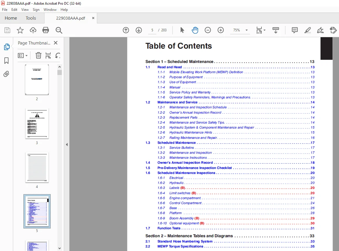
TABLE OF CONTENTS:
Skyjack SJ40 T+, SJ45 T+ Telescopic Booms Service Manual 229038AAA – PDF DOWNLOAD
Section 1 – Scheduled Maintenance 13
1.1 Read and Heed 13
1.1-1 Mobile Elevating Work Platform (MEWP) Definition 13
1.1-2 Purpose of Equipment 13
1.1-3 Use of Equipment 13
1.1-4 Manual 13
1.1-5 Service Policy and Warranty 13
1.1-6 Operator Safety Reminders, Warnings and Precautions 13
1.2 Maintenance and Service 14
1.2-1 Maintenance and Inspection Schedule 14
1.2-2 Owner’s Annual Inspection Record 14
1.2-3 Replacement Parts 14
1.2-4 Maintenance and Service Safety Tips 14
1.2-5 Hydraulic System & Component Maintenance and Repair 15
1.2-6 Hydraulic Maintenance Hints 15
1.2-7 Railing Maintenance and Repair 16
1.3 Scheduled Maintenance 17
1.3-1 Service Bulletins 17
1.3-2 Maintenance and Inspection 17
1.3-3 Maintenance Instructions 17
1.4 Owner’s Annual Inspection Record 18
1.5 Pre-Delivery/Maintenance Inspection Checklist 19
1.6 Scheduled Maintenance Inspections 20
1.6-1 Electrical 20
1.6-2 Hydraulic 20
1.6-3 Labels (B) 20
1.6-4 Limit switches (B) 20
1.6-5 Engine compartment 21
1.6-6 Control Compartment 24
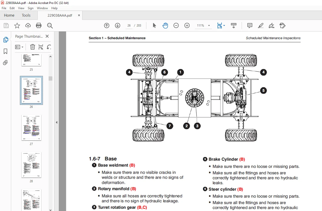
1.6-7 Base 26
1.6-8 Platform 28
1.6-9 Boom Assembly (B) 29
1.6-10 Optional equipment (B) 30
1.7 Function Tests 31
Section 2 – Maintenance Tables and Diagrams 33
2.1 Standard Hose Numbering System 33
2.2 MEWP Torque Specifications 35
Table of Contents
6
229038AAA SJ40 T+, SJ45 T+
2.3 Axle Torque Specifications 36
2.4 Torque Specifications for Fasteners (US) 37
2.5 Torque Specifications for Fasteners (Metric) 38
2.6 Torque Specifications for Hydraulic Couplings & Hoses 39
2.7 Axles Maintenance Intervals 40
2.8 Tire Specifications 41
2.9 Floor Loading Pressure 42
2.10 Hydraulic Specifications & Gear Oil 43
2.11 Specifications and Features – Dimensional Data 44
2.12 Specifications and Features – Performance and Speeds 45
2.13 Engine Specifications 46
2.14 Reach Diagram – SJ40 T+ 47
2.15 Dimensions – SJ40 T+ 48
2.16 Reach Diagram – SJ45 T+ 49
2.17 Dimensions – SJ45 T+ 50
2.18 Axle Oscillation Diagrams 51
Section 3 – System Component Identification and Schematics 53
3.1 Electrical Symbol Chart 54
3.2 Hydraulic Symbol Chart 55
3.3 Wire Number and Color Code 56
3.4 Hydraulic Parts List 57
3.5 Electrical Component Parts List 60
3.6 Rotary Manifold Port Identification 63
3.7 Brake Manifold Port Identification 64
3.8 System Pump Port Identification 65
3.9 Drive Pump Port Identification 66
3.10 Drive Motor Port Identification 67
3.11 Jib Valve Port Identification – SJ45 T+ 68
3.12 No Jib Valve Port Identifications – SJ40 T+ 69
3.13 Main Manifold Port Identification 71
3.14 Main Manifold Electrical Component Identification 72
3.15 Main Manifold Hydraulic Component Identification 73
3.16 Main Harness Wiring Diagram 74
3.17 Interface Harness – Deutz D2.9L & D2.2 75
3.18 ECU Engine Wiring Diagram – Deutz D2011 76
3.19 Engine Interface Harness – Deutz D2.9L 77
3.20 Engine Interface Harness – Kubota WG2503 78
3.21 Glow Plug Harness – Deutz D2.9L 79
3.22 Glow Plug Harness – Deutz D2011 80
3.23 Platform Harnesses 81
3.24 Limit Switch Connections 82
3.25 Load Sensing Cable Connectio 83
7
SJ40 T+, SJ45 T+ 229038AAA
3.26 Flashing Light Connection 84
3.27 Oil Cooler Harness Connections 85
3.28 Generator Wire Kit Connections 86
3.29 SGE Wiring Diagram 87
3.30 Load Circuit Wiring 88
3.31 Differential Lock Harness 89
3.32 Hydraulic Schematic 91
3.33 Platform Controls Wiring – SJ40 T+ 92
3.34 Platform Controls Wiring – SJ45 T+ ANSI/CSA & CE 93
3.35 Platform Controls Wiring – SJ45 T+ AS 94
3.36 Base Controls Wiring – SJ40 T+ 95
3.37 Base Controls Wiring – SJ40 T+ with Positive Air Shut-Off Option 96
3.38 Base Controls Wiring – SJ45 T+ ANSI/CSA & AS 97
3.39 Base Controls Wiring – SJ45 T+ ANSI/CSA & AS with Positive Air Shut-Off Option 98
3.40 Base Controls Wiring – SJ45 T+ CE 99
3.41 Electrical Schematic 100
3.42 Interface & Engine Electrical Schematic – Deutz D2.9L 101
3.43 Interface & Engine Electrical Schematic – Deutz D2.2 102
3.44 OEM Engine Harness – Deutz D2.2 103
3.45 Interface & Engine Electrical Schematic – Kubota WG2503 104
Section 4 – Troubleshooting Information 105
4.1 Introduction 105
4.2 Electrical System 106
4.2-1 All Controls are Inoperative from the Base or Platform Console 106
4.2-2 All Controls are Inoperative from the Base Console 108
4.2-3 The Engine will not Crank from the Base or Platform 108
4.2-4 The Engine will not Crank from the Base 109
4.2-5 The Engine will not Crank from the Platform 109
4.2-6 The Boom Controls are Inoperative (Drive Operates) 109
4.2-7 No Boom Up from the Base or Platform Controls 110
4.2-8 No Boom Up from the Base Console 110
4.2-9 No Boom Up from the Platform Console 110
4.2-10 No Boom Down from the Base or Platform Consoles 110
4.2-11 No Boom Down from the Base Console 111
4.2-12 No Boom Down from the Platform Console 111
4.2-13 No Turret Rotate Right from the Base or Platform Consoles 111
4.2-14 No Turret Rotate Right from the Platform Console 111
4.2-15 No Turret Rotate Right from the Platform Console 112
4.2-16 No Turret Rotate Left from the Base or Platform Consoles 112
4.2-17 No Turret Rotate Left from the Base Console 112
4.2-18 No Turret Rotate Left from the Platform Console 112
4.2-19 No Telescope Out from the Base or Platform Consoles 113
8
229038AAA SJ40 T+, SJ45 T+
4.2-20 No Telescope Out from the Base Console 113
4.2-21 No Telescope Out from the Platform Console 113
4.2-22 No Telescope In from the Base or Platform Consoles 114
4.2-23 No Telescope In from the Base Console 114
4.2-24 No Telescope In from the Platform Console 114
4.2-25 No Platform Level Up from the Base or Platform Consoles 114
4.2-26 No Platform Level Up from the Base Console 115
4.2-27 No Platform Level Up from the Platform Console 115
4.2-28 No Platform Level Down from the Base or Platform Consoles 115
4.2-29 No Platform Level Down from the Base Console 115
4.2-30 No Platform Level Down from the Platform Console 116
4.2-31 No Platform Rotate or Jib Functions from the Base or Platform Consoles 116
4.2-32 No Platform Rotate Right from the Base or Platform Consoles 116
4.2-33 No Platform Rotate Right from the Base Console 117
4.2-34 No Platform Rotate Right from the Platform Console 117
4.2-35 No Platform Rotate Left from the Base or Platform Consoles 117
4.2-36 No Platform Rotate Left from the Base Console 117
4.2-37 No Platform Rotate Left from the Platform Console 118
4.2-38 No Jib Up from the Base or Platform Consoles 118
4.2-39 No Jib Up from the Base Console 118
4.2-40 No Jib Up from the Platform Console 118
4.2-41 No Jib Down from the Base or Platform Consoles 119
4.2-42 No Jib Down from the Base Console 119
4.2-43 No Jib Down from the Platform Console 119
4.2-44 No Drive or Steer Functions 119
4.2-45 No Forward or Reverse Drive 120
4.2-46 No Forward Drive 120
4.2-47 No Reverse Drive 120
4.2-48 The Brake will not Release 121
4.2-49 No Left Steer 121
4.2-50 No Right Steer 122
4.2-51 The Directon Sensing is Inoperative 122
4.2-52 The Load Sense Indicates Overload or Overload Warning with the Platform Empty or Below
Weight 122
4.2-53 The Overload Indicator Light does not Turn On when the Platform is Overloaded 123
4.2-54 The Audible Alarm does not Turn On with the Platform Overloaded 123
4.3 Hydraulic System 124
4.3-1 All Controls are Inoperative 124
4.3-2 All Boom Functions are Inoperative 124
4.3-3 No Main Boom Up 124
4.3-4 No Main Boom Down 125
4.3-5 No Turret Rotate 125
4.3-6 No Boom Extend 126
9
SJ40 T+, SJ45 T+ 229038AAA
4.3-7 No Boom Retract 127
4.3-8 No Jib Up 127
4.3-9 No Jib Down 128
4.3-10 No Platform Rotation 128
4.3-11 Platform will not Level 129
4.3-12 Brake will not Release 130
4.3-13 Brake will not Engage 130
4.3-14 No Drive 130
4.3-15 Differential Lock will not Engage 131
4.3-16 No High Speed Drive 131
4.3-17 No Steer 131
4.3-18 Axle Will Not Oscillate 132
4.3-19 Axle Will Not Lock 132
Section 5 – Procedures 133
5.1 General 133
5.1-1 Safety and Workmanship 133
5.2 Platform 134
5.2-1 Human Machine Interface (HMI) 134
5.2-2 User Interface Keys 134
5.2-3 OCM Character Functions Charts 135
5.2-4 OCM Pin Reference 136
5.2-5 Platform Controller Voltage References 142
5.3 Boom 143
5.3-1 Check Wear Pads 143
5.3-2 Shim Wear Pads 143
5.3-3 Cable Carrier Repair 143
5.3-4 Rotary Actuator Bolt Torque Procedure 143
5.4 Turret 144
5.4-1 Check and Replace the High Pressure Filter 144
5.4-2 Adjust the Turret Rotation Gear Backlash 144
5.4-3 Check the Swing Drive Oil 145
5.4-4 Change the Swing Drive Oil 145
5.4-5 Battery Replacement 146
5.4-6 Turret Rotation Gear Bolt Torque Sequence 146
5.4-7 Electronic Tilt Switch Setup Procedure 147
5.4-8 Check Rotation Bearing for Axial Wear 149
5.5 Deutz Diesel Engines 150
5.5-1 Replace the Engine Oil and Filter 150
5.5-2 Replace the Fuel Filter 151
5.5-3 Replace the Air Filter 151
5.5-4 Check the Engine Belt 151
5.5-5 Check the Oil Cooler (Deutz D2011 only) 151
10
229038AAA SJ40 T+, SJ45 T+
5.5-6 Deutz D2.9L Fault Codes 152
5.6 Kubota WG2503 Dual Fuel Engine 172
5.6-1 Engine Parameter Display (KAntrak 1700) 172
5.6-2 Diagnostic Trouble Codes 173
5.6-3 Diagnostic Trouble Codes 174
5.6-4 Diagnostic Trouble Codes 175
5.6-5 Diagnostic Trouble Codes 176
5.6-6 Diagnostic Trouble Codes 177
5.6-7 ECU Pin Reference Chart (Kubota WG2503) 178
5.6-8 Fuse Box (Kubota WG2503) 179
5.6-9 MAP Sensor (Kubota WG2503) 180
5.6-10 IAT Sensor (Kubota WG2503) 180
5.6-11 ECT (Kubota WG2503) 181
5.6-12 TPS & Engine Speed (Kubota WG2503) 181
5.6-13 Fuel Temperature Sensor (Kubota WG2503) 182
5.6-14 Oil Pressure Sensor (Kubota WG2503) 182
5.7 Hydraulic Tank 183
5.7-1 Hydraulic Oil Replacement 183
5.7-2 Hydraulic Filter Replacement 183
5.8 Manifold and Hydraulic Pumps 184
5.8-1 Hydraulic Brake Pressure Adjustment 184
5.8-2 Hydraulic Standby Pressure Adjustment 185
5.8-3 Hydraulic High Pressure Adjustment 186
5.8-4 Hydraulic System Relief Valve Adjustment 187
5.8-5 Turret Rotate Relief Valve Adjustment 188
5.8-6 Platform Level Relief Valve Adjustment 188
5.8-7 Fly Boom Relief Valve Adjustment 189
5.8-8 Test Charge Pump Pressure on Drive Pump 189
5.8-9 Test Forward Drive Pressure on Drive Pump 190
5.8-10 Test Reverse Drive Pressure on Drive Pump 190
5.9 Axles 191
5.9-1 Change the Oil in the Axles 191
5.9-2 Check the Oil Level in the Torque Hubs 191
5.9-3 Change the Oil in the Torque Hubs 191
5.9-4 Check the Oil Level in the Axle Gearbox 192
5.9-5 Change the Oil in the Axle Gearbox 192
5.9-6 Oscillating Cylinder Bolt Replacement 193
5.9-7 Oscillating Cylinder Replacement 193
5.9-8 Bleed the Oscillating Axle Cylinders 195
5.9-9 Test the Oscillating Axle Cylinders 195
5.9-10 Pin Brake Adjustments 196
5.9-11 Brake Inspection 197
5.10 Grease Points 198
11
SJ40 T+, SJ45 T+ 229038AAA
5.10-1 Grease the Turret Ring Gear 198
5.10-2 Grease the Turret Swing Drive 198
5.10-3 Grease the Axles 199
5.10-4 Grease the Drive Shaft 199
5.11 Options 200
5.11-1 Generator Troubleshooting 200
5.11-2 Generator Frequency/Voltage Check & Adjustment 201
Customer Support: [email protected]
https://vimeo.com/876818649?share=copy
PLEASE NOTE:
- This is not a physical manual but a digital manual – meaning no physical copy will be couriered to you. The manual can be yours in the next 2 mins as once you make the payment, you will be directed to the download page IMMEDIATELY.
- This is the same manual used by the dealers inorder to diagnose your vehicle of its faults.
- Require some other service manual or have any queries: please WRITE to us at [email protected]
S.V