Trusted Business
Verified & Licensed
Virus Free Files
100% Safe Downloads
Secure Payment
SSL Protected
Instant Delivery
Available Immediately
Skyjack SJ6826 RT, SJ6832 RT Rough Terrain Scissors Parts Manual 213559AA – PDF DOWNLOAD
$28.95
Skyjack SJ6826 RT, SJ6832 RT Rough Terrain Scissors Parts Manual 213559AA – PDF DOWNLOAD
SJ6826 RT: A200000001 to A200999999
SJ6832 RT: A200000001 to A200999999
Instant PDF Download
Available immediately
Save to Your Device
Download & keep forever
Antivirus Scanned
100% virus-free
Trusted Worldwide
175,000+ customers
Description
Skyjack SJ6826 RT, SJ6832 RT Rough Terrain Scissors Parts Manual 213559AA – PDF DOWNLOAD
FILE DETAILS:
Skyjack SJ6826 RT, SJ6832 RT Rough Terrain Scissors Parts Manual 213559AA – PDF DOWNLOAD
Language : English
Pages : 228
Downloadable : Yes
File Type : PDF
DESCRIPTION:
Skyjack SJ6826 RT, SJ6832 RT Rough Terrain Scissors Parts Manual 213559AA – PDF DOWNLOAD
SJ6826 RT: A200000001 to A200999999
SJ6832 RT: A200000001 to A200999999
Foreword:
General:
The information contained in this manual is designed to aid the user in locating and identifying
replacement parts. Component parts of various assemblies and subassemblies comprising the work
platform are illustrated and accompanied by a descriptive parts list. Exploded drawings are used to
show relative location of component parts in disassembly order. If a part cannot be found in this
manual, contact your local Skyjack Parts Department for assistance.
Parts Ordering Information:
When ordering replacement parts, the complete part number and description should be used to ensure
proper identification and delivery of the desired item. This complete identification should also be
used when requesting equipment information.
When ordering replacement parts, the complete part number and description should be used to ensure
proper identification and delivery of the desired item. This complete identification should also be
used when requesting equipment information.
Method of Listing:
Parts are listed in order according to the reference number shown in the illustration, followed by
a full description based upon the “NOUN FIRST” method. That is, the noun name of the part is listed
first, then the modifying description information which serves to specifically identify the item.
For example: PIN, Clevis.
Assemblies at the beginning of a parts list may be identified with a reference letter: A, B, C,
etc. These letters are used to identify different configurations of the assembly. Individual parts
in these lists have
corresponding letters after their description to identify which assembly it is used in. If a part
does not have a reference letter, it is used in all of the assemblies.
Bullets (•) are used to show the assembly structure,
or parent/child relationship. A part listed at the beginning of the parts list without a bullet
before the description is the main assembly, and all of the parts below it with one bullet are the
subcomponent parts of that assembly. Two bullets denote a subcomponent of a subcomponent, etc.
Example:
Main Assembly A
• Part 1 (subcomponent of Main Assembly A)
• Part 2 (subcomponent of Main Assembly A)
• • Part 3 (subcomponent of Part 2)
Quantities:
The quantities required to complete the assembly are given for each part. If the quantity is (AR),
it is understood that the quantity may vary when the machine is equipped with certain options.
Order quantity as needed.
The quantities required to complete the assembly are given for each part. If the quantity is (AR),
it is understood that the quantity may vary when the machine is equipped with certain options.
Order quantity as needed.
How To Order Repair Parts:
1 . Address all orders to your local SKYJACK dealer.
2 . Specify model and serial number of the work platform (found on the serial number plate).
3 . List the quantity needed.
4 . List the length needed (if it is a bulk item).
5 . List the part number and description as shown in this manual for each item.
6 . Show the billing and shipping address and the name of the individual, if possible.
7 . Suggest the best routing.
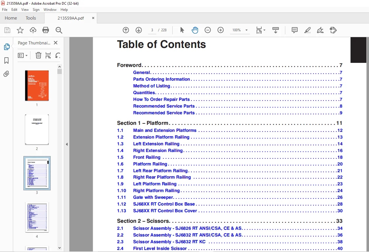
TABLE OF CONTENTS:
Skyjack SJ6826 RT, SJ6832 RT Rough Terrain Scissors Parts Manual 213559AA – PDF DOWNLOAD
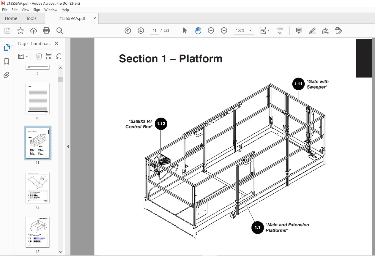
Foreword...............................................................  7
	General............................................................  7
	Parts Ordering Information.........................................  7
	Method of Listing..................................................  7
	Quantities.........................................................  7
	How To Order Repair Parts..........................................  7
	Recommended Service Parts..........................................  8
	Recommended Service Parts..........................................  9
Section 1 – Platform................................................... 11
	1.1  Main and Extension Platforms.................................. 12
	1.2  Extension Platform Railing.................................... 13
	1.3  Left Extension Railing........................................ 14
	1.4  Right Extension Railing....................................... 16
	1.5  Front Railing................................................. 18
	1.6  Platform Railing.............................................. 20
	1.7  Left Rear Platform Railing.................................... 21
	1.8  Right Rear Platform Railing................................... 22
	1.9  Left Platform Railing......................................... 23
	1.10  Right Platform Railing....................................... 24
	1.11  Gate with Sweeper............................................ 26
	1.12  SJ68XX RT Control Box Base................................... 28
	1.13  SJ68XX RT Control Box Cover.................................. 30
Section 2 – Scissors................................................... 33
	2.1  Scissor Assembly - SJ6826 RT ANSI/CSA, CE & AS................ 34
	2.2  Scissor Assembly - SJ6832 RT ANSI/CSA, CE & AS................ 36
	2.3  Scissor Assembly - SJ6832 RT KC .............................. 38
	2.4  First Level Inside Scissor.................................... 40
	2.5  Third Level Inside Scissor - Soft Stop........................ 41
	2.6  Middle Level Inside Scissor................................... 42
	2.7  Third Level Inside Scissor ................................... 43
	2.8  Top Level Inside Scissor...................................... 44
	2.9  Fifth Level Inside Scissor.................................... 45
	2.10  Fifth Level Outside Scissor.................................. 46
	2.11  First Level Outside Scissor.................................. 47
	2.12  Middle Level Outside Scissor................................. 48
	2.13  Fourth Level Outside Scissor................................. 49
	2.14  Upper Lift Cylinder.......................................... 50
	2.15  Lower Lift Cylinder - ANSI/CSA, CE, AS....................... 51
	2.16  Lower Lift Cylinder - KC..................................... 52
	2.17  Holding Valve - Upper Lift Cylinder.......................... 53
	2.19  Holding Valve - Lower Lift Cylinder - ANSI/CSA, CE & AS...... 54
	2.20  Holding Valve - Lower Lift Cylinder - KC..................... 55
	2.21  Beeper/ Angle Transducer - ANSI/CSA, CE, AS.................. 56
	2.22  Beeper - KC.................................................. 57
	2.23  Maintenance Support Stand.................................... 58
	2.24  Limit Switch................................................. 59
Section 3 – Base....................................................... 61
	3.1  Tires......................................................... 62
	3.2  Base Weldment................................................. 63
	3.3  SJ6826 RT Ladder Installation................................. 64
	3.4  SJ6832 RT Ladder Installation................................. 65
	3.5  Base Assembly - Outriggers.................................... 66
	3.6  Counterweight to Base - SJ6832 RT ANSI/CSA, KC................ 68
	3.7  Counterweight to Base - SJ6832 RT CE.......................... 69
	3.8  Cabinets to Base.............................................. 70
	3.9  Electrical Disconnect - SJ68XX RT............................. 71
	3.10  Outrigger Manifold........................................... 72
	3.11  Base Drive................................................... 74
	3.12  Splitter Manifold............................................ 78
	3.13  Tie Rod...................................................... 79
	3.14  Steer Cylinder............................................... 80
	3.15  Cushion Cylinder............................................. 82
	3.16  Scissor Guard - CE........................................... 83
Section 4 – Hydraulics and Electricals................................. 85
	4.1  Hydraulic Cabinet............................................. 86
	4.2  Main Manifold - Mounted with Outriggers....................... 88
	4.3  Hydraulic Modification - Soft Stop............................ 92
	4.4  Orifice....................................................... 93
	4.5  Base Assembly - Tanks and Hydraulics.......................... 94
	4.6  Hydraulic Oil Tank............................................ 96
	4.7  Fuel Tank..................................................... 98
	4.8  Hydraulic Cabinet Door........................................ 99
	4.9  Engine Cabinet Door...........................................100
	4.10  Engine Cabinet...............................................102
	4.11  Electric Panel Standard - SJ68XX RT, ANSI/CSA, AS............104
	4.12  Electric Panel Standard - SJ68XX RT, CE .....................106
	4.13  Electric Panel Standard - SJ6832 RT, KC .....................108
	4.14  Electric Panel - Positive Air Shutoff........................110
	4.15  Electric Panel - Soft Stop ..................................112
	4.16  Key Switch - 3 Way...........................................114
	4.17  Control Module...............................................115
	4.18  Power to Platform - ANSI/CSA, KC.............................116
	4.19  Power to Platform - CE/AS....................................118
Section 5 – Engines....................................................121
	5.1  Propane Bottle Mount..........................................122
	5.2  Engine - Kubota WG752 Dual Fuel Installation..................123
	5.3  Engine Tray...................................................124
	5.4  Vaporizer.....................................................125
	5.5  Engine - Kubota WG752 Dual Fuel...............................126
	5.6  Cooling - Kubota WG752 Dual Fuel..............................128
	5.7  Solenoid - Kubota WG752 Dual Fuel.............................130
	5.8  Air Intake - Kubota WG752 Dual Fuel...........................132
	5.9  Exhaust - Kubota WG752 Dual Fuel..............................133
	5.10  Engine Kit - Kubota WG752 Dual Fuel..........................134
	5.11  Engine - Kubota D902 Diesel..................................136
	5.12  Radiator Plate...............................................140
	5.13  Cooling - Kubota D902 Diesel.................................141
	5.14  Positive Air Shut Off Valve..................................142
Section 6 – Harness....................................................145
	6.1  Platform Control Harness......................................146
	6.2  Engine Pull Out Harness.......................................147
	6.3  Main Manifold Harness.........................................148
	6.4  Panel Control Cable...........................................150
	6.5  Outrigger Control Module Harness..............................151
	6.6  Horn Harness..................................................152
	6.7  Base to Platform Cable........................................153
	6.8  Pressure Switch Harness - KC..................................154
	6.9  Load Sense Harness............................................155
	6.10  Engine Harness - Kubota WG752 Dual Fuel......................156
	6.11  Engine Harness - Kubota D902 Diesel..........................158
	6.12  Pressure Transducer Harness..................................160
	6.13  Outrigger and Hydraulic Generator Harness ...................161
	6.14  Outrigger Auto Level Limit Switch Harness....................162
	6.15  Outrigger Manifold Harness...................................164
	6.16  Tilt Switch Harness - KC.....................................166
	6.17  Scissor Harness - KC.........................................167
	6.18  Beeper Harness...............................................168
	6.19  Outrigger Auto-leveling Control Module Harness (optional)....169
	6.20  Positive Air Shut Off Harness................................170
	6.21  Limit Switch Wiring..........................................172
	6.22  Limit Switch Wiring - Soft Stop..............................173
	6.23  Holding Harness..............................................174
	6.24  Outrigger Control Cable......................................175
Section 7 – Optional Equipment.........................................177
	7.1  Generator - ANSI/CSA..........................................178
	7.2  Generator Subassembly - ANSI/CSA..............................179
	7.3  Generator - CE................................................180
	7.4  Hydraulic Generator Hoses.....................................182
	7.5  Generator Hydraulic Fittings .................................184
	7.6  Elevate Telematics............................................185
	7.7  Outrigger Assembly............................................186
	7.8  Outrigger Assembly - Front....................................188
	7.9  Outrigger Assembly - Rear.....................................190
	7.10  Outrigger Control Box........................................192
	7.11  Outrigger - FR/RL, FL/RR.....................................194
	7.12  Outrigger Cylinder...........................................196
	7.13  Tool Caddy...................................................198
	7.14  Cold Weather Start...........................................199
	7.15  Heavy Duty Pipe Rack - ANSI..................................200
	7.16  Heavy Duty Pipe Rack - CE & AS...............................202
Section 8 – Hoses......................................................205
	8.1  Standard Hose Numbering System................................206
	8.2  Hose Kit......................................................208
	8.3  Fuel Hoses - Kubota WG752 Dual Fuel...........................212
	8.4  Fuel Hoses - Kubota D902 Diesel...............................214
Section 9 – Labels.....................................................217
	9.1  Label Kits....................................................219
	9.2  Labels - Right and Left.......................................220
	9.3  Labels - Front and Back.......................................222
	9.4  Labels - Top..................................................224
	9.5  Labels - Miscellaneous........................................225
	9.6  Labels - QR Code..............................................226
IMAGES PREVIEW OF THE MANUAL:
Need help? Contact: [email protected]
PLEASE NOTE:
- This is the same manual used by the dealers to diagnose and troubleshoot your vehicle
- You will be directed to the download page as soon as the purchase is completed. The whole payment and downloading process will take anywhere between 2-5 minutes
- Need any other service / repair / parts manual, please feel free to contact [email protected] . We still have 50,000 manuals unlisted
S.V