Skyjack SJ9241 RT SJ9250 RT Full-Size Rough Terrain Series Service Manual 143905AE – PDF DOWNLOAD
$25.95
Skyjack SJ9241 RT SJ9250 RT Full-Size Rough Terrain Series Service Manual 143905AE – PDF DOWNLOAD
Serial Numbers:
ANSI/CSA & AS
SJ 9250 50,000,513 TO 50,000,745
CE
SJ 9241 55,000,001 TO 55,000,032
SJ 9250 50,000,513 TO 50,000,745
Description
Skyjack SJ9241 RT SJ9250 RT Full-Size Rough Terrain Series Service Manual 143905AE – PDF DOWNLOAD
FILE DETAILS:
Skyjack SJ9241 RT SJ9250 RT Full-Size Rough Terrain Series Service Manual 143905AE – PDF DOWNLOAD
Language : English
Pages :192
Downloadable : Yes
File Type : PDF
DESCRIPTION:
Skyjack SJ9241 RT SJ9250 RT Full-Size Rough Terrain Series Service Manual 143905AE – PDF DOWNLOAD
Serial Numbers:
ANSI/CSA & AS
SJ 9250 50,000,513 TO 50,000,745
CE
SJ 9241 55,000,001 TO 55,000,032
SJ 9250 50,000,513 TO 50,000,745
SKYJACK is continuously improving and expanding product features on its equipment, therefore, specifications
and dimensions are subject to change without notice.
Aerial Platform Definition
A mobile device that has an adjustable position platform supported from ground level by a structure.
Purpose of Equipment
The SKYJACK Rough Terrain’s mid and full size aerial platforms are designed to transport and raise personnel, tools
and materials to overhead work areas.
Use of Equipment
The aerial platform is a highly maneuverable, mobile work station. Lifting and driving must be on a flat, level,
compacted surface. It can be driven over uneven terrain only when the platform is fully lowered.
Manuals
Operating
The operating manual is considered a fundamental part of the aerial platform. It is a very important way to
communicate necessary safety information to users and operators. A complete and legible copy of this manual
must be kept in the provided weather-resistant storage compartment on the aerial platform at all times.
Service & Maintenance
The purpose of this is to provide the customer with the servicing and maintenance procedures essential for
the promotion of proper machine operation for its intended purpose.
All information in this manual should be read and understood before any attempt is made to service the machine.
The updated copy of the manuals are found on the company’s website: www.skyjack.com.
Operator
The operator must read and completely understand both this operating manual and the safety panel label located
on the platform and all other warnings in this manual and on the aerial platform. Compare the labels on the aerial
platform with the labels found within this manual. If any labels are damaged or missing, replace them immediately.
IMAGES PREVIEW OF THE MANUAL:
TABLE OF CONTENTS:
Skyjack SJ9241 RT SJ9250 RT Full-Size Rough Terrain Series Service Manual 143905AE – PDF DOWNLOAD
Cover 1
ToC 5
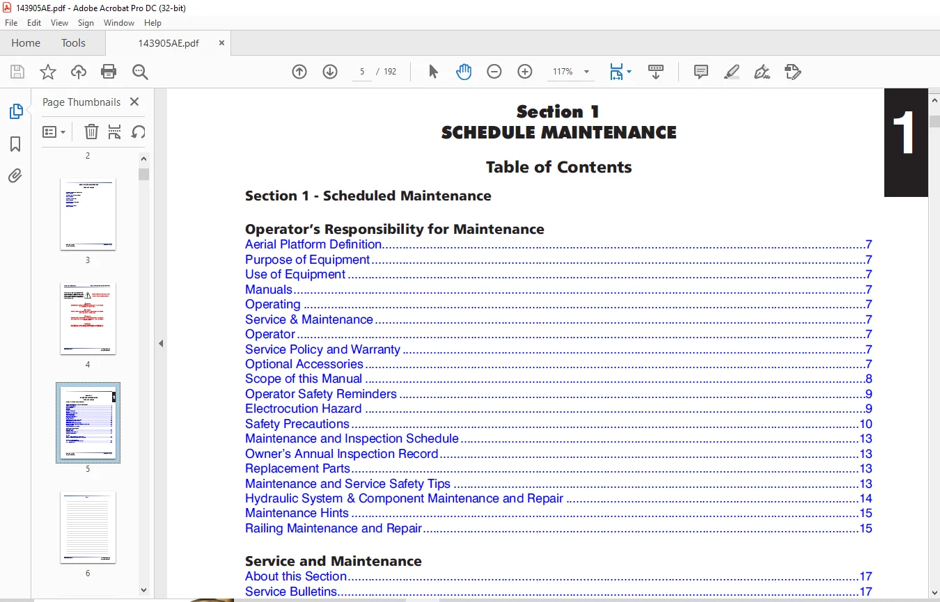
Section 1 – Scheduled Maintenance 5
Operator’s Responsibility for Maintenance 7
Aerial Platform Definition 7
Purpose of Equipment 7
Use of Equipment 7
Manuals 7
Operating 7
Service & Maintenance 7
Operator 7
Service Policy and Warranty 7
Optional Accessories 7
Scope of this Manual 8
Operator Safety Reminders 9
Electrocution Hazard 9
Safety Precautions 10
Maintenance and Inspection Schedule 13
Owner’s Annual Inspection Record 13
Replacement Parts 13
Maintenance and Service Safety Tips 13
Hydraulic System & Component Maintenance and Repair 14
Maintenance Hints 15
Railing Maintenance and Repair 15
Service and Maintenance 17
About this Section 17
Service Bulletins 17
Maintenance and Inspection 17
Maintenance Instructions 17
Tables 17
Table 1 1 Owner’s Annual Inspection Record 18
Table 1 2 Maintenance and Inspection Checklist 19
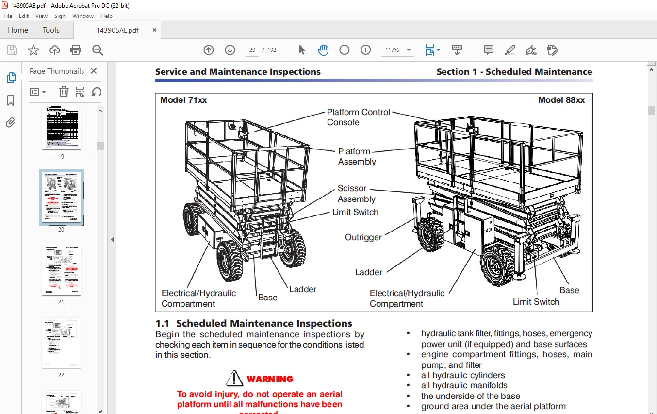
Scheduled Maintenance 19
1 1 Scheduled Maintenance Inspections 20
1 2 Function Tests 30
Section 2 – Maintenance Tables and Diagrams 39
Tables 39
Table 2 1a Specifications and Features – ANSI/CSA 40
Table 2 1b Specifications and Features – CE 41
Table 2 1c Specifications and Features – AS 42
Table 2 2a Maximum Platform Capacities (Evenly Distributed) – ANSI/CSA 44
Table 2 2b Maximum Platform Capacities (Evenly Distributed w/ Optional #7 Tires) – ANSI/CSA 45
Table 2 2c Maximum Platform Capacities (Evenly Distributed) – CE 46
Table 2 2d Maximum Platform Capacities (Evenly Distributed) – AS 47
Table 2 3a Tire Specifications – ANSI/CSA 48
Table 2 3b Tire Specifications – CE 49
Table 2 3c Tire Specifications – AS 50
Table 2 4a Floor Loading Pressure – ANSI/CSA 53
Table 2 4b Floor Loading Pressure – CE 54
Table 2 4c Floor Loading Pressure – AS 55
Table 2 5 Rough Terrain Scissor Fluids 56
Table 2 6 Torque Specifications 58
Section 3 – System Component Identification and Schematics 59
Charts 61
3 1 Hydraulic Symbol Chart 61
3 2 Electrical Symbol Chart 62
3 3 Hydraulic Component Parts List 63
Parts List 63
3 4 Electrical Component Parts List 66
3 5 Platform Control Console Wiring – All Options (ANSI/CSA) 73
Diagrams and Schematics 73
3 6 Platform Control Console Wiring – All Options (CE) 74
3 7 Control Cable Assemblies Diagram 75
3 8 Outrigger & Hydraulic Generator Control Console Wiring 76
3 9 Base Control Console Wiring (ANSI/CSA) 77
3 10 Base Control Console Wiring (CE) 78
3 11 Hydraulic Schematic (Cushman Axles) (Model 9241) 79
3 12 Hydraulic Schematic (Cushman Axles) (Model 9250) 80
3 13 Hydraulic Schematic (Dana Axles) 81
3 14 Hydraulic Manifold Components & Port Identifications 82
3 15 Main Manifold Wiring Diagram 83
3 16 Oil Cooler – Electrical Panel Diagram (ANSI/CSA Dual Fuel Engine) 84
3 17 Hydraulic Generator – Electrical Panel Diagram (ANSI/CSA Dual Fuel Engine) 85
3 18 Hydraulic Generator – Electrical Panel Diagram (ANSI/CSA Diesel Engine) 86
3 19 Hydraulic Generator – Electrical Panel Diagram (CE) 87
3 20 Emergency Lowering System – Wiring Diagram (ANSI/CSA) (Model 9250) 88
3 21 Emergency Lowering System – Wiring Diagram (CE) (Model 9250) 89
3 22 Emergency Lowering System – Electrical Wiring Diagram (CE) (Model 9241) 90
3 23 AutoLeveling Outrigger Connection Diagram 91
3 24 Powered Extension Platform – Electrical Wiring Diagram (Model 9250) 92
3 25 Horn, Light & Beeper Wiring Diagram (ANSI/CSA) (Model 9250) 93
3 26 Horn, Light, Beeper & Load Sensing Wiring Diagram 94
3 27 Electrical Inverter Wiring Diagram 95
3 28 Engine Wiring Diagram – Kubota Diesel Engine 97
3 29 Engine Harnesses – GM Dual Fuel Engine 98
3 30 Electrical Panel Diagram – ANSI/CSA (All Option) 99
3 31 Electrical Panel Diagram – CE (All Option) 100
3 32 Electrical Schematic – ANSI/CSA & AS (All Option with Kubota Diesel Engine) 101
3 33 Electrical Schematic – CE (All Option with Kubota Diesel Engine) 102
3 34 Electrical Schematic – ANSI/CSA & AS (All Options with GM Dual Fuel Engine) 103
3 35 Electrical Schematic – ANSI/CSA & AS (No Options with GM Dual Fuel Engine) 104
3 36 Interface & Engine Electrical Schematic – GM Dual Fuel Engine 105
Section 4 – Troubleshooting Information 106
Introduction 109
4 1-1 All Controls Inoperative 110
4 1-2 No Power to Platform (ANSI/CSA) 110
4 1-3 No Power to Platform (CE) 110
Electrical System 110
4 1-4 All Functions Inoperative from Platform 111
4 1-5 Engine will Not Crank from Platform 111
4 1-6 Engine will Not Crank from Platform Controls (Additional for GM Dual Fuel) 112
4 1-7 Engine will Not Crank from Base Controls (GM dual fuel) 113
4 1-8 Engine will Not Crank from Base Controls (Kubota diesel) 113
4 1-9 Engine Cranks but Stops Cranking after a few seconds 113
4 1-10 Glow Plugs Inoperative from Engine Controls 113
4 1-11 Glow Plugs Inoperative from Platform (Additional) 114
4 1-12 Engine Cranks but will Not Start (Kubota diesel) 114
4 1-13 Engine Cranks but will Not Start (GM dual fuel) 114
4 1-14 Mid Throttle Inoperative (on demand) (GM Dual Fuel) 116
4 1-15 High Throttle Inoperative 116
4 1-16 High Throttle Inoperative (additional for GM dual fuel) 117
4 1-17 Drive and Steer Inoperative 117
4 1-18 Brakes will Not Release 118
4 1-19 Steer Right Inoperative 119
4 1-20 Steer Left Inoperative 119
4 1-21 Reverse Drive Inoperative 120
4 1-22 Forward Drive Inoperative 120
4 1-23 First Drive Speed and Steering Inoperative 121
4 1-24 Second Drive Speed Inoperative 121
4 1-25 Third Drive Speed Inoperative 122
4 1-26 High/Low Range Speed Inoperative 123
4 1-27 Up Circuit Inoperative from Platform or Base 123
4 1-28 Platform will Not Lift from Platform or Base Controls with Outriggers Extended 124
4 1-29 Platform will Not Lift from Platform or Base Controls with Outriggers Retracted (lift operates correctly with outriggers extended) 126
4 1-30 Up Circuit Inoperative from Base (ANSI/CSA) 126
4 1-31 Up Circuit Inoperative from Base (CE) 126
4 1-32 Down Circuit Inoperative from Platform or Base 127
4 1-33 Down Circuit Inoperative from Base (ANSI/CSA) 128
4 1-34 Down Circuit Inoperative from Base (CE) 128
4 1-35 Powered Extension Platform Inoperative 129
4 1-36 Powered Extension Platform will Not Extend 129
4 1-37 Powered Extension Platform will Not Retract 130
4 1-38 Hydraulic Generator Inoperative 130
4 1-39 Hydraulic Generator will Not Shut Off from Generator Switch 131
4 1-40 All Outriggers Inoperative (Auto-level and manual) 131
4 1-41 All Outriggers Inoperative (Auto-level and manual from platform controls) 132
4 1-43 All Outriggers Inoperative (Auto-level) A: Led Power Indicator Light at Outrigger Control Module (OCM1) Not on Constant 132
4 1-44 All Outriggers Inoperative (Auto Level) B: Led Power Indicator Light at Outrigger Control Module (OCM1) Flashing 133
4 1-45 Left Front Outrigger Inoperative Manually 134
4 1-46 Right Front Outrigger Inoperative Manually 134
4 1-47 Right Rear Outriggers Inoperative Manually 134
4 1-48 Left Rear Outriggers Inoperative Manually 135
4 1-49 Individual Outrigger Functions Inoperative (Auto-level) 135
4 1-50 Auto-level Inoperative 135
4 1-51 Auto All Up Inoperative (Retract) 136
Hydraulic System 137
4 2-1 All Functions Inoperative 137
4 2-2 Steering Inoperative 137
4 2-3 Steer and First Drive Speed Inoperative 137
4 2-4 Lift and Second Drive Speed Inoperative 137
4 2-5 Drive Inoperative 137
4 2-6 Reverse Drive Inoperative 138
4 2-7 Forward Drive Inoperative 138
4 2-8 Brakes will Not Release 138
4 2-9 Brakes will Not Release (Internal Brake) 138
4 2-10 Brake Slips (Internal Brake) 138
4 2-11 Brake Drags or Runs Hot (Internal Brake) 139
4 2-12 Up Circuit Inoperative 139
4 2-13 Down Circuit Inoperative 139
4 2-14 Powered Extension Platform Inoperative 139
4 2-15 Hydraulic Generator Inoperative 139
4 2-16 All Outriggers Inoperative 140
4 2-17 Left Front Outrigger Inoperative 140
4 2-18 Right Front Outrigger Inoperative 140
4 2-19 Right Rear Outrigger Inoperative 140
4 2-20 Left Rear Outrigger Inoperative 140
4 2-21 Outriggers Drift In 140
Load Sensing System – CE 141
4 3-1 Flash Code F01: Check HWFS 141
4 3-2 Flash Code F02: Not Ground Mode 141
4 3-3 Flash Code F03: Not Stopped 141
4 3-4 Flash Code F04: Tilted 141
4 3-5 Flash Code F05: Bad Height 141
4 3-6 Flash Code F06: Check Elev 141
4 3-7 Flash Code F08: Check Elev 141
4 3-8 Flash Code F09: Bad Height 141
4 3-9 Flash Code F10: Bad Height 141
4 3-10 Flash Code F11: Not Up 141
4 3-11 Flash Code F12: Too Many 142
4 3-12 Flash Code F13: Low Height Range 142
4 3-13 Flash Code F14: Bad Height 142
4 3-14 Flash Code F15: Check Elev 142
4 3-15 Flash Code F16: Low Elev open 142
4 3-16 Flash Code F17: High Elev open 142
4 3-17 Flash Code F18: Low Elev close 142
4 3-18 Flash Code F19: High Elev close 142
4 3-19 Flash Code F20: Height<>0% 143
4 3-20 Flash Code F21: Height<>0% 143
4 3-21 Flash Code F22: Height<>100% 143
4 3-22 Flash Code F23: Height<>100% 143
4 3-23 Flash Code F24: Too Many 143
4 3-24 Flash Code F25: Check Elev 143
4 3-25 Flash Code F26: Check Elev 143
4 3-26 Flash Code F27: Bad Height 144
4 3-27 Flash Code F30: Bad Heights 144
4 3-28 Flash Code F31: Reject Curve 144
4 3-29 Flash Code F32: Reject Curve 144
4 3-30 Flash Code F33: Reject Curve 144
4 3-31 Flash Code F34: Reject Curve 144
4 3-32 Flash Code F40: Reject Delta 144
4 3-33 Flash Code F42: Low Pressure 145
4 3-34 Flash Code F43: High Pressure 145
4 3-35 Flash Code F44: Low Pressure 145
4 3-36 Flash Code F45: High Pressure 145
4 3-37 Flash Code F46: Check Elev 145
4 3-38 Flash Code F47: Check Elev 145
Section 5 – Procedures 148
General 149
Safety and Workmanship 149
Base 149
5 1-1 Hydraulic System and Brake Adjustment Procedure (If Equipped) 149
5 1-2 Brake Assembly and Disassembly (If Equipped) 150
Diagram 5 3 Multiple Disc Brake Assembly 151
5 1-3 Holding Torque Testing Procedure 152
5 1-4 Winching and Towing Procedures and Brake System 152
5 1-5 System Lift and Pressure Adjustment 153
5 1-7 Wheel Bolt/Nut Inspection and Torquing Procedure 155
5 1-8 Wheel Reinstallation and Torquing Procedure 155
5 1-9 Front Axle Hub Procedure 156
Engines 162
5 2-1 ECU Pin Reference Chart (GM) 162
5 2-2 Throttle Actuator (GM) 163
5 2-3 GM Map and IAT Sensor (GM) 164
5 2-4 Engine Coolant Temperature Sensor (GM) 165
5 2-5 LPG Temperature Sensor (GM) 166
5 2-6 Fuse Block Layout (GM) 167
5 2-7 Kubota Dual Fuel (DF972) Resistance Checks 168
Outrigger Option 169
5 3-1 Auto-Leveling Outrigger PC Board Layout 169
5 3-2 Outrigger Mechanical Limit Switch Wiring Diagram 170
5 3-3 Auto-Leveling Outrigger Setting and Error Codes 171
5 3-4 Auto-Leveling Outrigger Error Code Breakdown 172
5 3-5 Hand Held Calibration/Diagnostic Tool Key Functions 173
5 3-6 Outrigger Control Module Instructions 174
5 3-7 Auto-Leveling Outrigger Control Module Pin Reference Chart 177
Load Sensing System – CE 178
5 4-1 Control Module Pin Reference Chart 178
5 4-2 LED Error Codes – Quick Reference Chart 179
5 4-3 LED Error Codes – Code Breakdown Chart 180
5 4-6 Control Module Load Calibration – Code Messages & Definitions 182
5 4-7 Control Module Load Calibration Procedure 186
5 4-8 Curve/Group Codes Chart 190
Need help? Contact: [email protected]
PLEASE NOTE:
- This is the same manual used by the dealers to diagnose and troubleshoot your vehicle
- You will be directed to the download page as soon as the purchase is completed. The whole payment and downloading process will take anywhere between 2-5 minutes
- Need any other service / repair / parts manual, please feel free to contact [email protected] . We still have 50,000 manuals unlisted
S.M