Skyjack SJ9250 RT ROUGH TERRAIN SCISSORS PARTS MANUAL 165942AB – PDF DOWNLOAD
$26.95
Skyjack SJ9250 RT ROUGH TERRAIN SCISSORS PARTS MANUAL 165942AB – PDF DOWNLOAD
Serial Number(s):
SJRT 9250 50 001 121 to 50 001 152
Description
Skyjack SJ9250 RT ROUGH TERRAIN SCISSORS PARTS MANUAL 165942AB – PDF DOWNLOAD
FILE DETAILS:
Skyjack SJ9250 RT ROUGH TERRAIN SCISSORS PARTS MANUAL 165942AB – PDF DOWNLOAD
Language : English
Pages :186
Downloadable : Yes
File Type : PDF
DESCRIPTION:
Skyjack SJ9250 RT ROUGH TERRAIN SCISSORS PARTS MANUAL 165942AB – PDF DOWNLOAD
Serial Number(s):
SJRT 9250 50 001 121 to 50 001 152
General
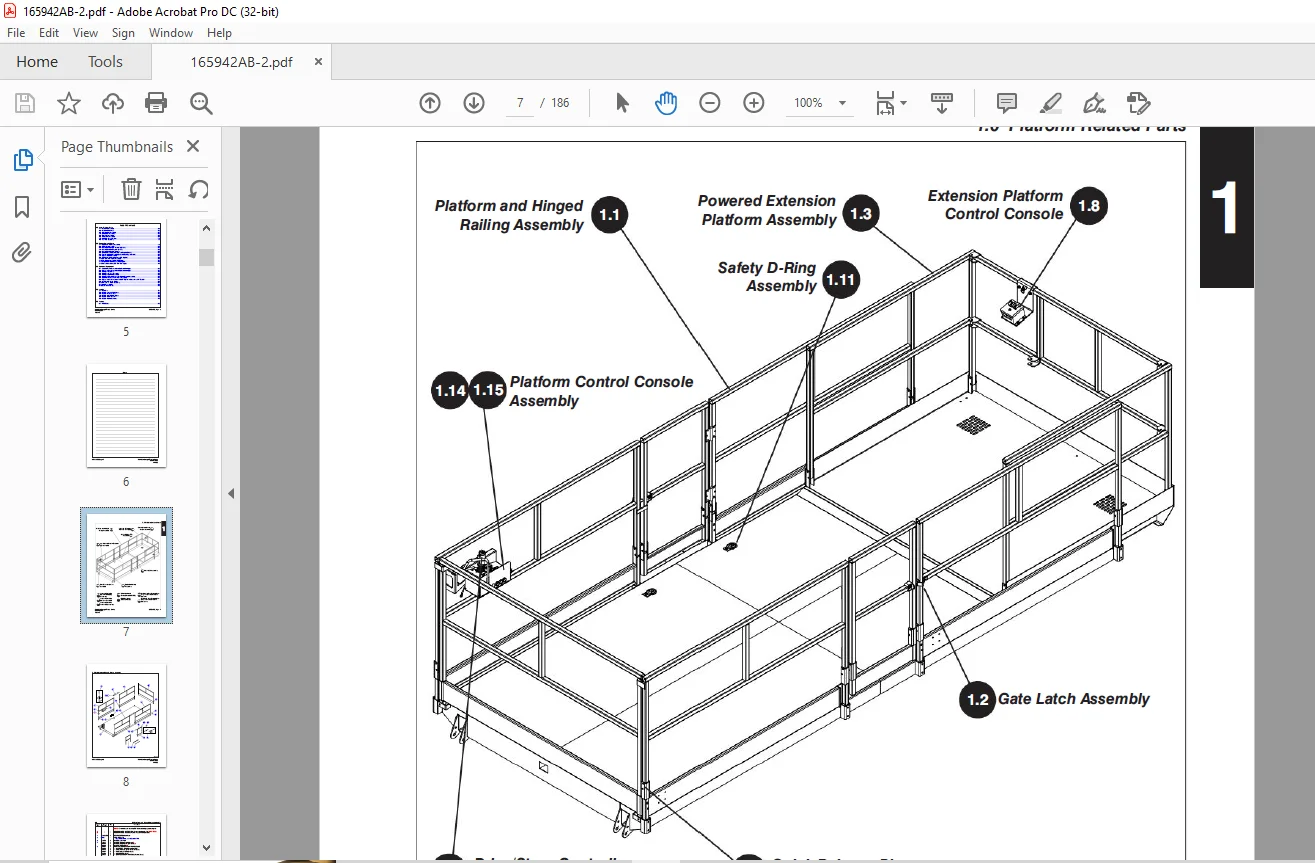
The information contained in this section is designed to aid the user in locating and identifying replacement parts. Component parts of various assemblies and subassemblies comprising the work platform are illustrated and accompanied by a descriptive parts list. Exploded drawings are used to show relative location of component parts in disassembly order. If a part cannot be found in this section, order by work platform model number and serial number, giving a complete description of the part.
Parts Ordering Information
When ordering replacement parts, the complete part number and description should be used to ensure proper identification and delivery of the desired item. This complete identification should also be used when requesting equipment information
Method of Listing
- Parts are listed in order according to the reference number shown in the illustration, followed by a full description based upon the “NOUN FIRST” method. That is, the noun name of the part is listed first, then the modifying description information which serves to specifically identify the item. For example: PIN, Clevis. Assemblies or groups are shown at the beginning of a parts list and are identified with the letter references A, B, C, etc. Individual parts in these lists have corresponding letters after their description to identify which assembly or group it is used in. Individual parts without identifying letters are used in all the assemblies or group shown at the beginning of the parts list. Descriptions preceded with an (•) indicates a serviceable component or attaching hardware for the higher level assembly
- If an index number initially starts with the letter “K”, for example “K1”, means it’s a kit. Any item(s) included in a kit will not have an index number.
IMAGES PREVIEW OF THE MANUAL:
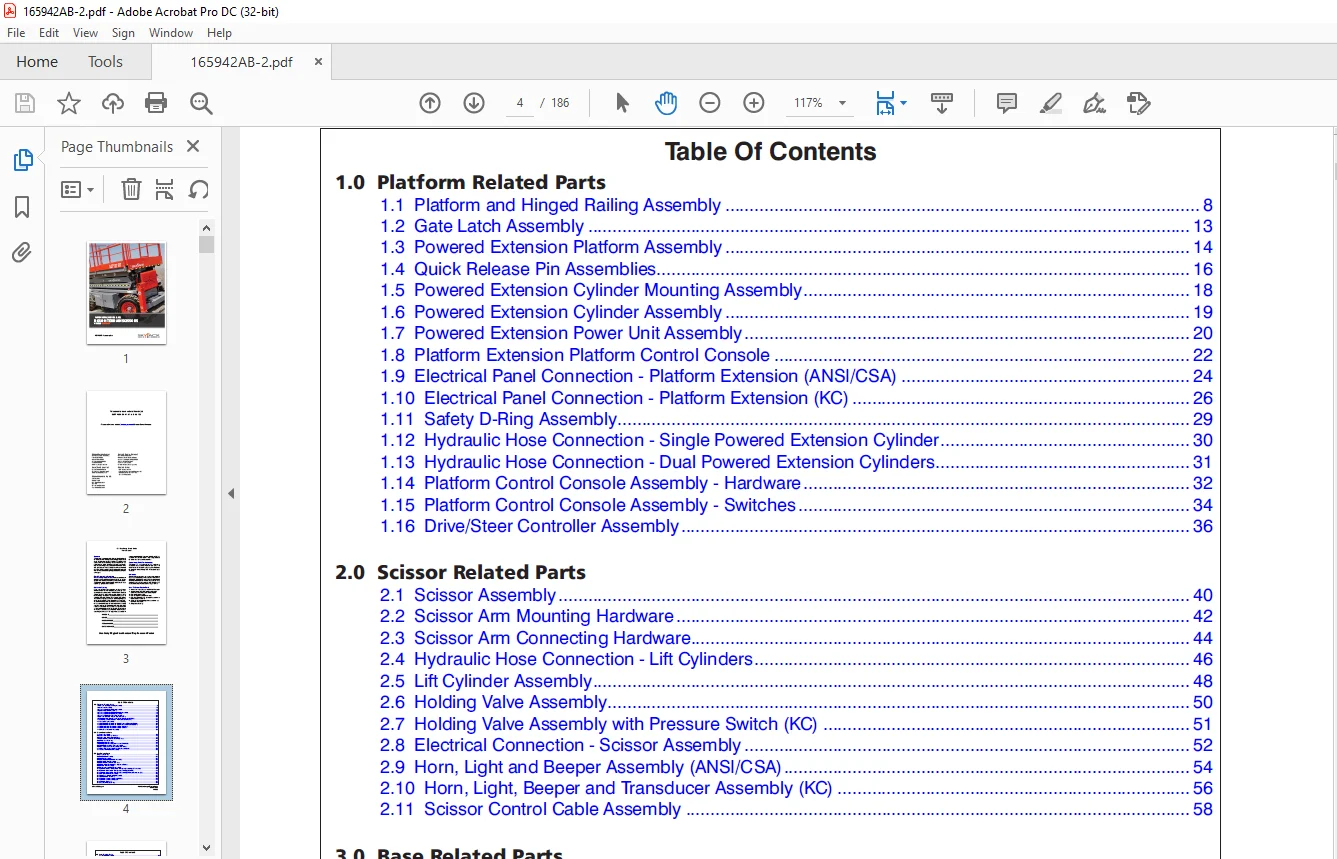
TABLE OF CONTENTS:
Skyjack SJ9250 RT ROUGH TERRAIN SCISSORS PARTS MANUAL 165942AB – PDF DOWNLOAD
Table of Contents 4
1 0 Platform Related Parts 7
1 1 Platform and Hinged Railing Assembly 8
1 2 Gate Latch Assembly 13
1 3 Powered Extension Platform Assembly 14
1 4 Quick Release Pin Assemblies 16
1 5 Powered Extension Cylinder Mounting Assembly 18
1 6 Powered Extension Cylinder Assembly 19
1 7 Powered Extension Power Unit Assembly 20
1 8 Platform Extension Platform Control Console 22
1 9 Electrical Panel Connection – Platform Extension (ANSI/CSA) 24
1 10 Electrical Panel Connection – Platform Extension (KC) 26
1 11 Safety D-Ring Assembly 29
1 12 Hydraulic Hose Connection – Single Powered Extension Cylinder 30
1 13 Hydraulic Hose Connection – Dual Powered Extension Cylinders 31
1 14 Platform Control Console Assembly – Hardware 32
1 15 Platform Control Console Assembly – Switches 34
1 16 Drive/Steer Controller Assembly 36
2 0 Scissor Related Parts 39
2 1 Scissor Assembly 40
2 2 Scissor Arm Mounting Hardware 42
2 3 Scissor Arm Connecting Hardware 44
2 4 Hydraulic Hose Connection – Lift Cylinders 46
2 5 Lift Cylinder Assembly 48
2 6 Holding Valve Assembly 50
2 7 Holding Valve Assembly with Pressure Switch (KC) 51
2 8 Electrical Connection – Scissor Assembly 52
2 9 Horn, Light and Beeper Assembly (ANSI/CSA) 54
2 10 Horn, Light, Beeper and Transducer Assembly (KC) 56
2 11 Scissor Control Cable Assembly 58
3 0 Base Related Parts 61
3 1 Base Assembly 62
3 2 Fuel Cabinet Assembly 64
3 3 Fuel Tank Assembly 67
3 4 Hydraulic/Electrical Cabinet Assembly 68
3 5 Hydraulic Oil Tank Assembly 72
3 6 Hydraulic Hose Connections – Base 74
3 7 Hydraulic Hose Connections – Hydraulic Cabinet 76
3 8 Cushion Valve Assembly 78
3 9 Emergency Lowering Valve Assembly 79
3 10 Electrical Cabinet Components – Emergency Lowering and Powerdeck 80
3 11 Electrical Connections – Emergency Lowering (ANSI/CSA) 82
3 12 Electrical Connections – Emergency Lowering & Platform Retraction (KC) 84
3 13 Motion Control Valve Assembly 86
3 14 Auto Reset Brake Manifold Assembly 87
3 15 Main Manifold Assembly 88
3 16 Electrical Panel Assembly (ANSI/CSA) 90
3 17 Electrical Panel Assembly (KC) 92
3 18 Electrical Harnesses 94
3 19 Base Controls Assembly 96
4 0 Axle Related Parts 97
4 1 Front Axle Assembly 98
4 2 Front Axle Hardware 102
4 3 Steer Cylinder Assembly 104
4 4 Drive Motor Assembly 105
4 5 Drive Shaft Assembly 106
4 6 Center Drive Assembly 108
4 7 Brake Caliper and Mount 110
4 8 Rear Axle Assembly 112
5 0 Engine Related Parts 115
5 1 Engine Roll-Out Tray Assembly 116
5 2 Engine Control Panel 120
5 3 Kubota Diesel Engine Assembly (D1305) 122
5 4 Kubota Diesel Fuel System (D1305) 128
5 5 Kubota Diesel Engine Harness 130
5 6 Air Intake Assembly (Kubota Diesel Engine D1305) 132
5 8 Exhaust Manifold Assembly (Kubota Diesel Engine D1305) 133
5 7 Hydraulic Pump Assembly 134
5 9 Engine Roll-Out Tray Hardware (GM Engine) 136
5 10 GM Dual Fuel Engine Assembly 138
5 11 Bell Housing Assembly (GM Engine) 144
5 12 Engine Interface Harness (GM Engine) 146
5 13 Hose Connections – GM Dual Fuel Engine 148
6 0 Optional Equipment 151
6 1 Electrical Panel Connections – Hydraulic Outrigger 152
6 2 Hydraulic Hose Connections – Hydraulic Outrigger 154
6 3 Outrigger Assembly 156
6 4 Outrigger Cylinder Assembly 158
6 5 Outrigger Manifold Assembly 159
6 6 Outrigger/Hydraulic Generator Control Console Assembly 160
6 7 3500W Generator and Oil Cooler Assembly 162
6 8 Hydraulic Hose Connections – 3500W Hydraulic Generator and Oil Cooler 164
6 9 Air Hose to Platform Option 166
6 10 Platform AC Outlet Assembly 167
6 11 Cold Start Option 168
6 12 Gate Hand Rail Kit 169
7 0 Labels 171
7 1 Label Kits 171
7 2 Labels – Left and Right Sides 172
7 3 Labels – Front and Rear 174
7 4 Labels – Hydraulic Outriggers 175
7 5 Labels – Miscellaneous 176
7 6 Labels – Control Consoles 178
8 0 Tables 181
8 1 Fluid Tables 182
Questions? Email us: [email protected]
PLEASE NOTE:
- This is the same manual used by the DEALERSHIPS to SERVICE your vehicle.
- The manual can be all yours – Once payment is complete, you will be taken to the download page from where you can download the manual. All in 2-5 minutes time!!
- Need any other service / repair / parts manual, please feel free to contact us at heydownloadss @gmail.com . We may surprise you with a nice offer
S.M