Skyjack SJ9250 RT ROUGH TERRAIN SCISSORS Service Manual 167323AFA – PDF DOWNLOAD
$25.95
Skyjack SJ9250 RT ROUGH TERRAIN SCISSORS Service Manual 167323AFA – PDF DOWNLOAD
Serial Number(s):
SJRT 9250 50 001 153 – 50 999 999
Description
Skyjack SJ9250 RT ROUGH TERRAIN SCISSORS Service Manual 167323AFA – PDF DOWNLOAD
FILE DETAILS:
Skyjack SJ9250 RT ROUGH TERRAIN SCISSORS Service Manual 167323AFA – PDF DOWNLOAD
Language : English
Pages :172
Downloadable : Yes
File Type : PDF
DESCRIPTION:
Skyjack SJ9250 RT ROUGH TERRAIN SCISSORS Service Manual 167323AFA – PDF DOWNLOAD
Serial Number(s):
SJRT 9250 50 001 153 – 50 999 999
1.1 Read and Heed
- The purpose of this is to provide the customer with the servicing and maintenance procedures essential for the promotion of proper machine operation for its intended purpose.
- All information in this manual should be read and understood before any attempt is made to service the machine. The updated copy of the manuals are found on the company’s
IMAGES PREVIEW OF THE MANUAL:
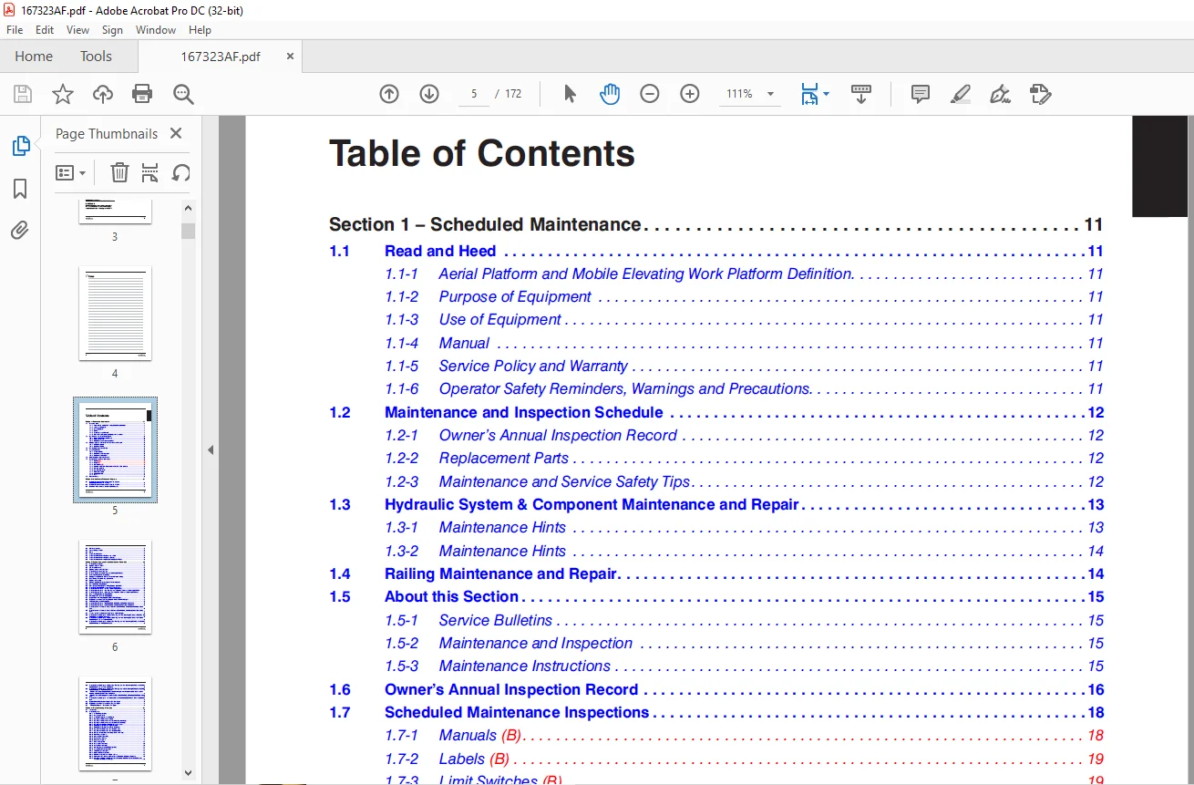
TABLE OF CONTENTS:
Skyjack SJ9250 RT ROUGH TERRAIN SCISSORS Service Manual 167323AFA – PDF DOWNLOAD
Section 1 – Scheduled Maintenance 11
1 1 Read and Heed 11
1 1-1 Aerial Platform and Mobile Elevating Work Platform Definition 11
1 1-2 Purpose of Equipment 11
1 1-3 Use of Equipment 11
1 1-4 Manual 11
1 1-5 Service Policy and Warranty 11
1 1-6 Operator Safety Reminders, Warnings and Precautions 11
1 2 Maintenance and Inspection Schedule 12
1 2-1 Owner’s Annual Inspection Record 12
1 2-2 Replacement Parts 12
1 2-3 Maintenance and Service Safety Tips 12
1 3 Hydraulic System & Component Maintenance and Repair 13
1 3-1 Maintenance Hints 13
1 3-2 Maintenance Hints 14
1 4 Railing Maintenance and Repair 14
1 5 About this Section 15
1 5-1 Service Bulletins 15
1 5-2 Maintenance and Inspection 15
1 5-3 Maintenance Instructions 15
1 6 Owner’s Annual Inspection Record 16
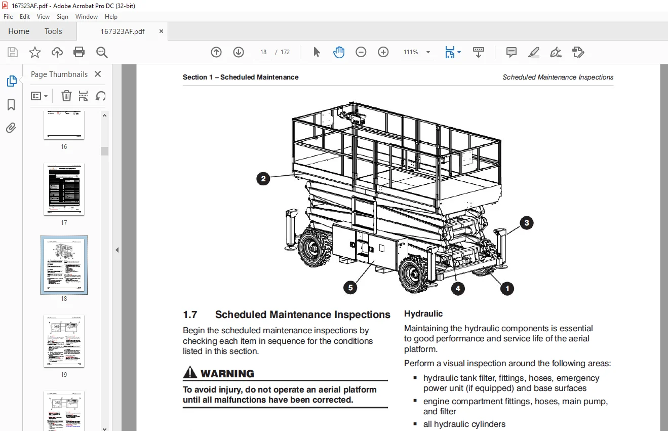
1 7 Scheduled Maintenance Inspections 18
1 7-1 Manuals (B) 18
1 7-2 Labels (B) 19
1 7-3 Limit Switches (B) 19
1 7-4 Electrical and Control Components and Hydraulic Compartment 19
1 7-5 Fuel Compartment 21
1 7-6 Engine Compartment 22
1 7-7 Platform Assembly 24
1 7-8 Lifting Mechanism 25
1 7-9 Base 28
1 8 Function Tests 30
Section 2 – Maintenance Tables and Diagrams 31
2 1 Specifications and Features 50 001 320 – 50 999 999
(Including 50 001 302 – 50 001 307) 32
2 2 Specifications and Features 50 001 153 – 50 001 320 33
2 3 Maximum Platform Capacities (Evenly Distributed) 34
Table of Contents
6
167323AFA SJ9250 RT
2 4 Tire Specifications 35
2 5 Floor Loading Pressure 37
2 6 Fluids 38
2 7 Torque Specifications 39
2 8 Torque Specifications for Fasteners (Imperial) 40
2 9 Torque Specifications for Fasteners (Metric) 41
2 10 Torque Specifications for Hydraulic Couplings and Hoses 42
Section 3 – System Component Identification and Schematics 43
3 1 Electrical Symbol Chart 44
3 2 Hydraulic Symbol Chart 45
3 3 AC Cord Color Code 46
3 4 Hydraulic Component Parts List 47
3 5 Electrical Component Parts List 50
3 6 Platform Control Console Wiring – All Options (ANSI/CSA) 56
3 7 Control Cable Assemblies Diagram 57
3 8 Outrigger and Hydraulic Generator Control Console Wiring 58
3 9 Base Control Console Wiring (ANSI/CSA) 59
3 10 Hydraulic Schematic 61
3 11 HydraulicManifold Components and Port Identification 62
3 12 Main Manifold Wiring Diagram 63
3 13 Emergency Lowering System Wiring Diagram (ANSI/CSA) 64
3 14 Electrical Wiring Diagram – Powered Extension Platform 65
3 15 Electrical Panel Diagram – Oil Cooler Option (ANSI/CSA) 66
3 16 Electrical Panel Diagram – Dual Fuel Engine with Hydraulic Generator Option (ANSI/CSA) 67
3 17 Electrical Panel Diagram – Diesel Engine with Hydraulic Generator Option (ANSI/CSA) 68
3 18 Auto-Leveling Outrigger Wiring Diagram 69
3 19 Horn, Light, and Beeper Wiring Diagram 70
3 20 Engine Harness Wiring Diagram – Kubota Diesel Engine 71
3 21 Engine Interface Harness Wiring Diagram – Kubota Dual Fuel Engine 72
3 22 Telematics Harness Wiring Diagram 73
3 23 Electrical Panel Diagram – S/N 50 002 025 50 002 025, 50 002 029 – 50 999 999 74
3 24 Electrical Panel Diagram – S/N 50 002 028, 50 002 027, 50 001 153 – 50 002 024 75
3 25 Electric Panel with Positive Air Shutoff Option – S/N 50 002 025, 50 002 026, 50 002 029 – 50 999
999 76
3 26 Electric Panel with Positive Air Shutoff Option – S/N 50 002 028, 50 002 027, 50 001 153 – 50 002
024 77
3 27 Positive Air Shutoff Harness Wiring Diagram – Diesel Engine 78
3 28 Electrical Schematic Diagram – Kubota Diesel Engine with All Option (ANSI/CSA) – S/N 50 002 025,
50 002 026, 50 002 029 – 50 999 999 79
3 29 Electrical Schematic Diagram – Kubota Diesel Engine with All Option (ANSI/CSA) – S/N 50 002
028, 50 002 027, 50 001 153 – 50 002 024 80
3 30 Electrical Schematic Diagram – Kubota Dual Fuel Engine with All Options (ANSI/CSA) – S/N 50 002
025, 50 002 026, 50 002 029 – 50 999 999 81
7
SJ9250 RT 167323AFA
3 31 Electrical Schematic Diagram – Kubota Dual Fuel Engine with All Options (ANSI/CSA) – S/N 50 002
028, 50 002 027, 50 001 1533 – 50 002 024 82
3 32 Electrical Schematic Diagram – Kubota Dual Fuel Engine with No Options (ANSI/CSA) – S/N 50 002
025, 50 002 026, 50 002 029 – 50 999 999 83
3 33 Electrical Schematic Diagram – Kubota Dual Fuel Engine with No Options (ANSI/CSA) – S/N 50
002 028, 50 002 027, 50 001 153 – 50 002 024 84
3 34 Electrical Schematic Diagram – All Options (KC) – S/N 50 002 025, 50 002 026, 50 002 029 – 50 999
999 85
3 35 Electrical Schematic Diagram – All Options (KC) – S/N 50 002 028, 50 002 027, 50 001 153 – 50 002
024 86
3 36 Engine Electrical Schematic – Kubota Dual Fuel Engine 87
3 37 Engine Interface Harnesses – Kubota Dual Fuel Engine 88
3 38 ECU Wiring Diagram – Kubota Dual Fuel Engine 89
Section 4 – Troubleshooting Information 91
4 1 Introduction 91
4 2 Electrical System 91
4 2-1 All Controls Inoperative 92
4 2-2 No Power to Platform 92
4 2-3 All Functions Inoperative from Platform 93
4 2-4 Engine Does Not Crank from Platform 93
4 2-5 Engine Does Not Crank from Base Controls (Kubota dual fuel) 94
4 2-6 Engine Does Not Crank from Base Controls (Kubota diesel) 95
4 2-7 Engine Cranks but Stops Cranking after a few seconds 95
4 2-8 Glow Plugs Inoperative from Engine Controls 95
4 2-9 Glow Plugs Inoperative from Platform (Additional) 95
4 2-10 Engine Cranks but Does Not Start (Kubota diesel) 96
4 2-11 Engine Cranks but Does Not Start (Kubota dual fuel 96
4 2-12 Mid Throttle Inoperative (on demand) (Kubota Dual Fuel) 97
4 2-13 High Throttle Inoperative 97
4 2-14 Drive and Steer Inoperative 98
4 2-15 Brakes Do Not Release 99
4 2-16 Steer Right Inoperative 99
4 2-17 Steer Left Inoperative 100
4 2-18 Reverse Drive Inoperative 101
4 2-19 Forward Drive Inoperative 101
4 2-20 First Drive Speed and Steering Inoperative 102
4 2-21 Second Drive Speed Inoperative 102
4 2-22 Third Drive Speed Inoperative 103
4 2-23 High/Low Range Inoperative 104
4 2-24 Up Circuit Inoperative from Platform or Base 105
4 2-25 Platform Does Not Lift from Platform or Base Controls with Outriggers Extended 106
4 2-26 latform Does Not Lift from Platform or Base Controls with Outriggers Retracted (lift operates
correctly with outriggers extended) 107
8
167323AFA SJ9250 RT
4 2-27 Up Circuit Inoperative from Base 108
4 2-28 Down Circuit Inoperative from Platform or Base 108
4 2-29 Down Circuit Inoperative from Base 109
4 2-30 Powered Extension Platform Inoperative 109
4 2-31 Powered Extension Platform Does Not Extend 110
4 2-32 Powered Extension Platform Does Not Retract 110
4 2-33 Hydraulic Generator Inoperative 110
4 2-34 Hydraulic Generator Does Not Shut Off from Generator Switch 111
4 2-35 All Outriggers Inoperative (Auto-level and manual) 111
4 2-36 All Outriggers Inoperative (Auto-level and manual from platform controls) 112
4 2-37 All Outriggers Inoperative (Base Controls) 112
4 2-38 All Outriggers Inoperative (Auto-level)
A: Led Power Indicator Light at Outrigger Control Module (OCM1) Not on Constant 112
4 2-39 All Outriggers Inoperative (Auto Level)
B: Led Power Indicator Light at Outrigger Control Module (OCM1) Flashing 113
4 2-40 Left Front Outrigger Inoperative Manually 114
4 2-41 Right Front Outrigger Inoperative Manually 114
4 2-42 Right Rear Outriggers Inoperative Manually 114
4 2-43 Left Rear Outriggers Inoperative Manually 115
4 2-44 Individual Outrigger Functions Inoperative (Auto-level) 115
4 2-45 Auto-level Inoperative 115
4 2-46 Auto All Up Inoperative (Retract) 116
4 3 Hydraulic System 117
4 3-1 All Functions Inoperative 117
4 3-2 Steering Inoperative 117
4 3-3 Steer and First Drive Speed Inoperative 117
4 3-4 Lift and Second Drive Speed Inoperative 117
4 3-5 Drive Inoperative 117
4 3-6 Reverse Drive Inoperative 118
4 3-7 Forward Drive Inoperative 118
4 3-8 Brakes Do Not Release 118
4 3-9 Up Circuit Inoperative 118
4 3-10 Down Circuit Inoperative 119
4 3-11 Powered Extension Platform Inoperative 119
4 3-12 Hydraulic Generator Inoperative 119
4 3-13 All Outriggers Inoperative 119
4 3-14 Left Front Outrigger Inoperative 119
4 3-15 Right Front Outrigger Inoperative 120
4 3-16 Right Rear Outrigger Inoperative 120
4 3-17 Left Rear Outrigger Inoperative 120
4 3-18 Outriggers Drift In 120
9
SJ9250 RT 167323AFA
Section 5 – Procedures 121
5 1 General 122
5 1-1 Safety and Workmanship 122
5 1-2 Hydraulic System 122
5 2 Base 122
5 2-1 Brake Caliper Adjustment 122
5 2-2 Bleeding the Brake Caliper 124
5 2-3 Changing the Hydraulic Oil 126
5 2-4 Wheel Bolt/Nut Inspection and Torquing Procedure 126
5 2-5 Wheel Reinstallation and Torquing Procedure 127
5 2-6 Front Axle Hub Procedure 127
5 2-7 Electronic Tilt Switch Setup Procedure 129
5 2-8 Reconnecting the Platform Control Box for Use from the Ground 132
5 2-9 Tightening and Torque Recommendations for Hydraulic Couplings and Hoses 133
5 2-10 Checking the Holding Valve 134
5 2-11 System Pressure Setting 135
5 2-12 Lift Pressure Setting 136
5 2-13 Grease Points 137
5 3 Engine 138
5 3-1 Fan Belt Replacement and Adjustment 138
5 3-2 Engine Throttle Setting (Kubota D1305) 139
5 3-3 Replacing the Air Cleaner Element 140
5 3-4 Replacing the Fuel Filter Element 141
5 3-5 Bleeding the Fuel System of Air 141
5 3-6 Replacing the Oil Filter Cartridge 142
5 3-7 Changing the Oil 142
5 3-8 Checking and Replenishing the Radiator Coolant Level 143
5 3-9 Draining and Refilling the Radiator 143
5 3-10 Engine Parameter Display
(KAntrak 1700) 144
5 3-11 Kubota 972 and 2503 – DTC 145
5 4 Outriggers 152
5 4-1 Auto-Leveling Outrigger PC Board Layout 152
5 4-2 Outrigger Mechanical Limit Switch Wiring Diagram 153
5 4-3 Auto-Leveling Outrigger Setting and Error Codes 154
5 4-4 Auto-Leveling Outrigger Error Code Breakdown 155
5 4-5 Hand Held Calibration/Diagnostic Tool Key Functions 156
5 4-6 Outrigger Control Module Instructions 157
5 4-7 Auto-Leveling Outrigger Control Module Pin Reference Chart 161
5 4-8 Outrigger Upper Limit Switch (LS61, LS62, LS63, LS64) Replacement and Adjustment 162
5 4-9 Outrigger Lower Limit Switch (LS65, LS66, LS67, LS68) Replacement and Adjustment 163
5 5 Scissors 165
5 5-1 End of Stroke Limit Switch (LS4) Replacement and Adjustment 165
5 5-2 High Speed Cutout (LS5) and Lift Cutout (LS1) Limit Switch Replacement and Adjustment 167
5 6 Platform 169
5 6-1 Gate Springe Hinge Adjustment
Questions? Email us: [email protected]
PLEASE NOTE:
- This is the same manual used by the DEALERSHIPS to SERVICE your vehicle.
- The manual can be all yours – Once payment is complete, you will be taken to the download page from where you can download the manual. All in 2-5 minutes time!!
- Need any other service / repair / parts manual, please feel free to contact us at heydownloadss @gmail.com . We may surprise you with a nice offer
S.M