Skyjack SJIII 3215 SJIII 3219 DC ELECTRIC SCISSORS Service Manual 157927AM – PDF DOWNLOAD
$25.95
Skyjack SJIII 3215 SJIII 3219 DC ELECTRIC SCISSORS Service Manual 157927AM – PDF DOWNLOAD
Description
Skyjack SJIII 3215 SJIII 3219 DC ELECTRIC SCISSORS Service Manual 157927AM – PDF DOWNLOAD
FILE DETAILS:
Skyjack SJIII 3215 SJIII 3219 DC ELECTRIC SCISSORS Service Manual 157927AM – PDF DOWNLOAD
Language : English
Pages :154
Downloadable : Yes
File Type : PDF
DESCRIPTION:
Skyjack SJIII 3215 SJIII 3219 DC ELECTRIC SCISSORS Service Manual 157927AM – PDF DOWNLOAD
SJIII 3215 10 000 631 to 10 999 999
SJIII 3219 22 022 793 to 22 999 999
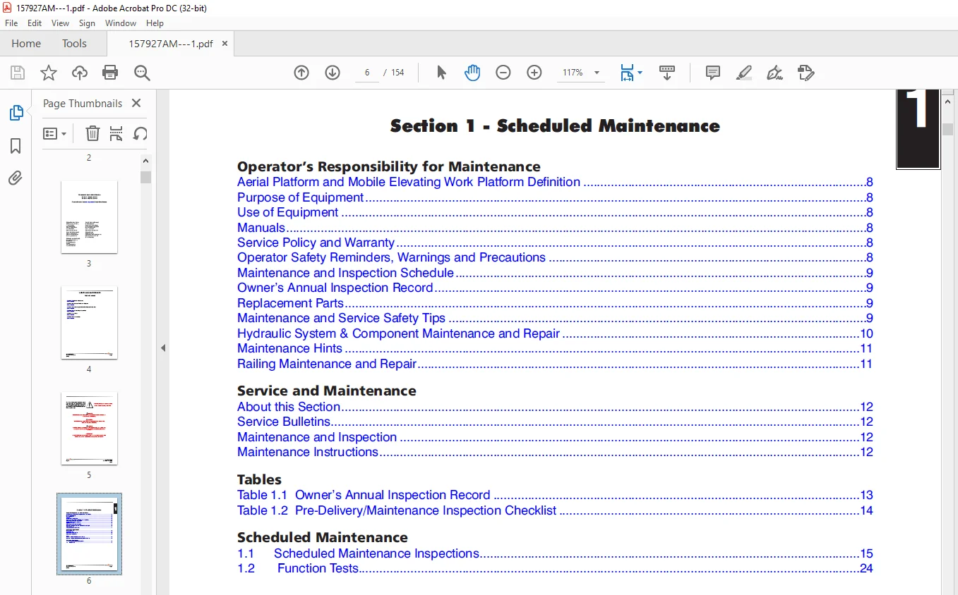
Section 1 – Scheduled Maintenance
and dimensions are subject to change without notice.
Aerial Platform and Mobile Elevating Work Platform Definition
A mobile device that has a positionable platform supported from ground level by a structure.
Purpose of Equipment
The SKYJACK SJIII DC Electric series aerial platforms are designed to transport and raise personnel, tools and
materials to overhead work areas.
Use of Equipment
The aerial platform is a highly maneuverable, mobile work station. Work platform elevation and elevated driving
must only be done on a firm level surface.
Operating
IMAGES PREVIEW OF THE MANUAL:
TABLE OF CONTENTS:
Skyjack SJIII 3215 SJIII 3219 DC ELECTRIC SCISSORS Service Manual 157927AM – PDF DOWNLOAD
Cover 2
Table of Contents 4
Section 1 – Scheduled Maintenance 6
Operator’s Responsibility for Maintenance 7
Aerial Platform and Mobile Elevating Work Platform Definition 7
Purpose of Equipment 7
Use of Equipment 7
Manuals 7
Service Policy and Warranty 7
Operator Safety Reminders, Warnings and Precautions 7
Maintenance and Inspection Schedule 8
Owner’s Annual Inspection Record 8
Replacement Parts 8
Maintenance and Service Safety Tips 8
Hydraulic System & Component Maintenance and Repair 9
Maintenance Hints 10
Railing Maintenance and Repair 10
Service and Maintenance 11
About this Section 11
Service Bulletins 11
Maintenance and Inspection 11
Maintenance Instructions 11
Tables 12
Table 1 1 Owner’s Annual Inspection Record 12
Table 1 2 Pre-Delivery/Maintenance Inspection Checklist 13
Scheduled Maintenance 14
1 1 Scheduled Maintenance Inspections 14
1 2 Function Tests 25
Section 2 – maintenance Tables and Diagrams 25
Tables 26
Table 2 1 Specifications and Features 27
Table 2 2 Floor Loading Pressure 28
Table 2 3 Maximum Platform Capacities (Evenly Distributed) 30
Table 2 4 Torque Specifications 31
Table 2 5 Torque Specifications for Fasteners (Imperial) 32
Table 2 6 Torque Specifications for Fasteners (Metric) 33
Table 2 7 Torque Specifications for Hydraulic Couplings & Hoses 34
Section 3 – System component identification and schematics 36
Charts 37
3 1 Electrical Symbol Chart 37
3 2 Hydraulic Symbol Chart 38
3 3 Wire Number and Color Code 39
3 4 AC Cord Color Code 40
Parts List 42
3 5 Hydraulic Manifold and Port Identifications 42
3 6 Hydraulic Schematic Parts List 43
3 7a Electrical Component Parts List 44
3 7b Electrical Component Parts List (Continued) 45
3 7c Electrical Component Parts List (Continued) 46
Diagrams and Schematics 47
3 8a Platform Control Console Diagram 47
3 8b Platform Control Console Diagram – Long Cable Option 48
3 9a Base Control Console Diagram (Including EE-Rated) 49
3 9b Base Control Console Diagram (Non EE-Rated only) 50
3 10a Scissor Arm Control Cable 51
3 10b Scissor Arm Control Cable 52
3 11 Holding Valve & Horn/Flashing Light Harnesses Diagrams 53
3 12 Limit Switch Assemblies Diagrams 54
3 13 Electrical Inverter Schematic & Panel Diagram (With Timer Cutout Relay) 55
3 14 Electrical Harness – ZTR Telematics 56
3 15 Hydraulic Schematic (Model 3215) 58
3 16 Hydraulic Schematic (Model 3219) 59
3 17 Main Manifold Harness and Holding Valve Harness 60
3 18 Main Manifold Harness and Holding Valve Harness (EE-Rated) 61
3 19 Elevate19 Telematics Harness 62
3 20a Electrical Panel Diagram 63
3 20b Electrical Panel Diagram 64
3 20c Electrical Panel Diagram 65
3 21a Electrical Panel Diagram (EE Rated) 66
3 21b Electrical Panel Diagram (EE Rated) 67
3 21c Electrical Panel Diagram (EE Rated) 68
3 22 Electrical Panel with Inverter Option 69
3 23 Horn/Tilt Switch/Flashing Light Diagram 70
3 24a Electrical Schematic (Equipped with no options) 71
3 24b Electrical Schematic (Equipped with no options) 72
3 24c Electrical Schematic (Equipped with no options) 73
3 25a Electrical Schematic (ANSI/CSA – Equipped with All options) 74
3 25b Electrical Schematic (ANSI/CSA – Equipped with All options) 75
3 25c Electrical Schematic (ANSI/CSA – Equipped with All options) 76
3 26a Electrical Schematic (EE Rated – Equipped with no options) 77
3 26b Electrical Schematic (EE Rated – Equipped with no options) 78
3 26c Electrical Schematic (EE Rated – Equipped with no options) 79
3 27a Electrical Schematic (EE Rated – Equipped with All options) 80
3 27b Electrical Schematic (EE Rated – Equipped with All options) 81
Section 4 – Troubleshooting Information 82
Introduction 83
Electrical System 84
4 1-1 All Controls Inoperative 84
4 1-2 All Controls Except for Down Function Inoperative 84
4 1-3 All Controls Inoperative From Base Control Console 85
4 1-4 All Controls Inoperative From Platform Control Console 85
4 1-5 No Drive or Up Function from Platform or Base Controls (CE) 85
4 1-6 No Down or Reverse Only Function from Platform Controls 86
4 1-7 No Up or Forward Only Function from Platform Control Console 86
4 1-8 No Up Function from Platform or Base Control Console 86
4 1-9 No Down Function from Platform or Base Control Console (ANSI/CSA) 87
4 1-10 No Down Function from Platform or Base Control Console (CE) 87
4 1-11 No Up Function from Base Control Console 87
4 1-12 No Down Function from Base Control Console 88
4 1-13 Platform Lowers Slowly from Platform and Base (Model 3215) 88
4 1-14 Platform does not Decelerate when Lowering (Model 3215) 88
4 1-15 Platform Lifts Slowly from Platform and Base Control console 88
4 1-16 Steer Only Inoperative 88
4 1-17 Drive Only Inoperative 88
4 1-18 No Drive or Steer when Platform Fully Lowered 89
4 1-19 No Drive or Steer when Platform Elevated 89
4 1-20 Elevated Drive Speed Does Not Activate 89
4 1-21 Work Platform Drives in Slow Speed Only 89
4 1-22 Forward Drive Function Inoperative 90
4 1-23 Reverse Drive Function Inoperative 90
4 1-24 Brake will not Release 90
4 1-25 Two or more Functions at one time 90
Hydraulic System 91
4 2-1 All Functions Inoperative 91
4 2-2 All Functions Sluggish 91
4 2-3 Platform Drifts Down 91
4 2-4 Platform Lifts Slowly 91
4 2-5 Platform Does Not Lift 91
4 2-6 Platform will not Lower 92
4 2-7 Platform Lowers Slowly 92
4 2-8 Platform Drives Slow 92
4 2-9 Platform will not Drive in Forward or Reverse 92
4 2-10 Brake(s) will not Release 93
4 2-11 Platform does not Steer 93
Section 5 – Procedures 94
Service & Maintenance 95
General 95
Safety and Workmanship 95
Platform 95
5 1-1 OEM Controller Electronics Information 95
5 1-2 OEM Controller Troubleshooting 96
5 1-3 OEM Controller Switch Wiring 99
5 1-4 Gate Spring Hinge Adjustment 100
Base 102
5 2-1 System Relief Pressure Adjustment 102
5 2-2 Lift Pressure Adjustment 102
5 2-3 Electronic Tilt Switch Setup Procedure 103
5 2-4 Pothole Limit Switches (LS4 & LS5) Replacement and Adjustment 107
5 2-5 Wheel Replacement and Torquing Procedure 108
5 2-6 Battery Maintenance 114
5 2-7 Charger Maintenance – Delta-Q 114
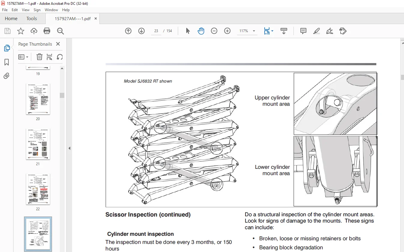
Scissors 121
5 3-1 High Speed Cutout (LS1B) & Deceleration (LS7) Limit Switches Replacement and Adjustment 121
Section 6 – APPENDIX A 124
Parts List 128
6 1 Electrical Component Parts List 128
Diagrams and Schematics 129
6 2 Platform Control Console Diagram – Motor Controller 129
6 3a Electrical Panel Diagram – Motor Controller 130
6 3b Electrical Panel Diagram – Motor Controller 131
6 4 Electrical Panel M/C with Inverter Option 132
6 5 Main Manifold Harness – Motor Controller 133
6 6 Hydraulic Schematic – Motor Controller 134
6 7a Electrical Schematic – Motor Controller 135
6 7b Electrical Schematic – Motor Controller 136
Troubleshooting 138
Introduction – Troubleshooting 138
Electrical System 139
6 7-1 All Controls Inoperative 139
6 7-2 All Controls Except for Down Function Inoperative 140
6 7-3 All Controls Inoperative From Base Control Console 140
6 7-4 No Up Function from Base Control Console 140
6 7-5 Up Function Slow from Base Control Console 141
6 7-6 No Down Function from Base Control Console 141
6 7-7 All Controls Inoperative From Platform Control Console 142
6 7-8 No Up Function from Platform Controls 142
6 7-9 Up Function Slow from Platform Control Console 143
6 7-10 No Down Function from Platform Controls 143
6 7-11 Steer Only Inoperative 143
6 7-12 Right Steer Inoperative 144
6 7-13 Left Steer Inoperative 144
6 7-14 Drive Only Inoperative 144
6 7-15 No Drive or Steer when Platform Fully Lowered 144
6 7-16 No Drive or Steer when Platform Elevated 145
6 7-17 Platform Drives in Slow Speed Only 145
6 7-18 Brake will not Release 145
6 7-19 Forward Drive Function Inoperative 145
6 7-20 Reverse Drive Function Inoperative 146
Hydraulic System 146
6 8-1 All Function Inoperative 146
6 8-2 All System Sluggish 146
6 8-3 Platform Drifts Down 146
6 8-4 Platform Lifts Slowly 146
6 8-5 Platform does not Lift 146
6 8-6 Platform will not Lower 147
6 8-7 Platform Lowers Slowly (3215 only) 147
6 8-8 Platform Drives Slow 147
6 8-9 Platform will not Drive in Forward or Reverse 147
6 8-10 Brake(s) will not Release 147
6 8-11 Platform does not Steer 147
Service & Maintenance 148
General 148
Safety and Workmanship 148
Platform 148
6 9-1 OEM Controller Electronics Information 148
6 9-2 OEM Controller Troubleshooting 149
6 9-3 OEM Controller Switch Wiring 150
6 9-4 Gate Spring Hinge Adjustment 151
Base 152
6 9-5 System Relief Pressure Adjustment 152
6 9-6 Lift Pressure Adjustment 152
6 9-7 Resistor – Voltage Divider 153
Customer Support: [email protected]
PLEASE NOTE:
- This is the SAME manual used by the dealers to troubleshoot any faults in your vehicle. This can be yours in 2 minutes after the payment is made.
- Contact us at [email protected] should you have any queries before your purchase or that you need any other service / repair / parts operators manual.
S.M