★ TRUSTED BY 321,897+ PROFESSIONALS WORLDWIDE
🏒
Trusted Business
Verified & Licensed
πŸ›‘οΈ
Virus Free Files
100% Safe Downloads
πŸ”’
Secure Payment
SSL Protected
⚑
Instant Delivery
Available Immediately
Sale!

Skyjack SJIII 3220 3226 4620 4626 4632 DC Electric Scissor Lift Service Manual – 157928AP 2025 PDF

Original price was: $39.95.Current price is: $24.95.

Complete 2025 Skyjack service manual (157928AP) for SJIII 3220, 3226, 4620, 4626, and 4632 DC electric scissor lifts. Covers scheduled maintenance, hydraulic and electrical schematics, component parts lists, detailed troubleshooting, and step-by-step repair procedures – including the Motor Controller appendix.

⚑
Instant PDF Download
Available immediately
πŸ’Ύ
Save to Your Device
Download & keep forever
πŸ›‘οΈ
Antivirus Scanned
100% virus-free
🌍
Trusted Worldwide
175,000+ customers

Description

Skyjack SJIII 3220 3226 4620 4626 4632 Service Manual – Document 157928AP

This is the full Skyjack service manual for the SJIII series DC electric scissor lifts, published under document number 157928AP in 2025. It covers the SJIII 3220, SJIII 3226, SJIII 4620, SJIII 4626, and SJIII 4632 mobile elevating work platforms (MEWPs), and is written for the technician who maintains, diagnoses, and repairs these machines. Everything from the pre-delivery inspection checklist to the Motor Controller schematics lives in one document.

File Details

  • Manual Type: Service Manual
  • Brand: Skyjack
  • Models Covered: SJIII 3220, SJIII 3226, SJIII 4620, SJIII 4626, SJIII 4632
  • Document Number: 157928AP
  • Edition / Year: 2025
  • Language: English
  • File Format: PDF
  • Page Count: 186 pages

Chapters Covered

  • Section 1 – Scheduled Maintenance
    • Operator’s Responsibility for Maintenance
    • Maintenance and Inspection Schedule
    • Owner’s Annual Inspection Record
    • Pre-Delivery / Maintenance Inspection Checklist
    • Scheduled Maintenance Inspections
    • Function Tests
  • Section 2 – Maintenance Tables and Diagrams
    • Specifications and Features
    • Floor Loading Pressure
    • Maximum Platform Capacities
    • Torque Specifications (Imperial, Metric, Hydraulic Couplings and Hoses)
  • Section 3 – System Component Identification and Schematics
    • Electrical Symbol Chart
    • Hydraulic Symbol Chart
    • Wire Number and Color Code
    • AC Cord Color Code
    • Hydraulic and Electrical Component Parts Lists
    • Hydraulic Manifold and Port Identifications
    • Platform, Base, Scissor Arm and Powered Extension Control Diagrams
    • Limit Switch Assembly and Harness Wire Diagrams
    • Hydraulic and Electrical Schematics
  • Section 4 – Troubleshooting Information
    • Electrical System Troubleshooting (controls, drive, steer, lift, brake, speed, torque)
    • Hydraulic System Troubleshooting (lift, lower, drive, brake, steer, extension platform)
  • Section 5 – Procedures
    • OEM Controller Electronics, Troubleshooting, and Switch Wiring
    • Gate Spring Hinge Adjustment
    • Railing Modification and Platform Mounting Hardware
    • System Relief and Lift Pressure Adjustment
    • Electronic Tilt Switch Setup
    • Pothole Limit Switch Replacement and Adjustment
    • Wheel Replacement and Torquing Procedure
    • Hydraulic Coupling and Hose Torque Recommendations
    • Battery and Delta-Q Charger Maintenance
    • High Speed Cutout and Drive Override Limit Switch Service
  • Section 6 – Motor Controller (Appendix A)
    • Electrical Component Parts List (Motor Controller)
    • Platform Control Console and Scissor Assembly Limit Switch Diagrams
    • Electrical Panel Diagrams (standard, Powerdeck, Inverter options)
    • Main Manifold Harness – Motor Controller
    • Motor Controller Hydraulic Schematics (32XX and 46XX)
    • Motor Controller Electrical Schematics
    • Motor Controller Electrical and Hydraulic Troubleshooting
    • OEM Controller Setup, Switch Wiring, and Voltage Divider

Across the six sections, this Skyjack SJIII service manual gives a technician everything needed to keep an SJIII 3220, 3226, 4620, 4626, or 4632 running safely and to specification. Section 1 alone carries the pre-delivery and frequent-inspection checklists, the owner’s annual inspection record, and step-by-step scheduled-maintenance inspections for the hydraulic, electrical, battery, and structural systems. Section 2 supplies the specifications, floor-loading pressures, capacity charts, and torque values that turn those inspections into measured, verifiable work. Section 3 is the reference layer – symbol charts, wire color codes, parts lists, and the hydraulic and electrical schematics that make circuit-level diagnosis possible.

Sections 4 through 6 are the working core. Section 4’s troubleshooting trees are organised by symptom (all controls inoperative, no down function, platform will not lower, brake will not release, elevated drive speed not activating, and many more) and list probable causes with remedies. Section 5 contains the actual procedures – pressure adjustment, tilt switch programming, limit switch replacement and adjustment, wheel torquing, pothole limit switch setup, and battery and charger service. Section 6 (Appendix A) extends the whole manual into Motor Controller-equipped machines, with its own parts list, panel diagrams for standard, Powerdeck, and Inverter configurations, hydraulic and electrical schematics, and a dedicated troubleshooting chapter.

Model and Serial Number Coverage

Serial number applicability as printed in the manual: SJIII 3220 from 60 002 259 to 60 999 999; SJIII 3226 from 27 006 432 to 27 999 999; and the 46xx / 47xx series from 70 007 139 to 70 999 999. Motor controller-equipped machines (identified by an MC label on the side of the machine or platform control box) are covered separately in Section 6 – Appendix A, with their own serial number breakdown reference charts.

Complete PDF Bookmark Tree

Complete Bookmarks

The complete bookmarks in the β€œSkyjack SJIII 3220 3226 4620 4626 4632 DC Electric Scissor Lift Service Manual – 157928AP 2025 PDF” are as follows:

Coverp. 1
Table of Contentsp. 5
Section 1 – scheduled maintenancep. 7
Aerial Platform and Mobile Elevating Work Platform Definitionp. 8
Purpose of Equipmentp. 8
Use of Equipmentp. 8
Manualsp. 8
Service Policy and Warrantyp. 8
Operator Safety Reminders, Warnings and Precautionsp. 8
Operator’s Responsibility for Maintenancep. 8
Maintenance and Inspection Schedulep. 9
Owner’s Annual Inspection Recordp. 9
Replacement Partsp. 9
Maintenance and Service Safety Tipsp. 9
Hydraulic System & Component Maintenance and Repairp. 10
Maintenance Hintsp. 11
Railing Maintenance and Repairp. 11
Service and Maintenancep. 12
About this Sectionp. 12
Service Bulletinsp. 12
Maintenance and Inspectionp. 12
Maintenance Instructionsp. 12
Tablesp. 13
Table 1.1 Owner’s Annual Inspection Recordp. 13
Table 1.2 Pre-Delivery/Maintenance Inspection Checklistp. 14
Scheduled Maintenancep. 15
1.1 Scheduled Maintenance Inspectionsp. 15
1.2 Function Testsp. 25
Section 2 – maintenance tables and diagramsp. 27
Tablesp. 27
Table 2.1 Specifications and Featuresp. 28
Table 2.1 Specifications and Features (Continued)p. 29
Table 2.2 Floor Loading Pressurep. 30
Table 2.3 Maximum Platform Capacities (Evenly Distributed)p. 32
Table 2.4 Torque Specificationsp. 33
Table 2.5 Torque Specifications for Fasteners (Imperial)p. 34
Table 2.6 Torque Specifications for Fasteners (Metric)p. 35
Table 2.7 Torque Specifications for Hydraulic Couplings & Hosesp. 36
Section 3 – System component idenTification and schematicsp. 37
3.1 Electrical Symbol Chartp. 39
Chartsp. 39
3.2 Hydraulic Symbol Chartp. 40
3.3 Wire Number and Color Codep. 41
3.4 AC Cord Color Codep. 42
Parts Listp. 43
3.5 Hydraulic Schematic Parts Listp. 43
3.5 Hydraulic Schematic Parts List (Continued)p. 44
3.6 Electrical Components Parts Listp. 45
3.6a Electrical Component Parts List (Continued)p. 46
3.6b Electrical Component Parts List (Continued)p. 47
3.7a Hydraulic Manifold and Port Identificationsp. 48
3.7b Hydraulic Manifold and Port Identificationsp. 49
Diagrams and Schematicsp. 50
3.8a Platform Control Console Diagramp. 50
3.8b Platform Control Console Diagram – Long Cable Optionp. 51
3.9a Powerdeck Platform Modification Diagramp. 52
3.9b Powerdeck Platform Modification Diagramp. 53
3.10a Powered Extension Platform Control Console and Harnessp. 54
3.10b Powered Extension Platform Control Consolep. 55
3.11a Base Control Console Diagram (Including EE-Rated)p. 56
3.11b Base Control Console Diagram (Non EE-Rated Only)p. 57
3.12a Scissor Arm Control Cable Diagramp. 58
3.12b Scissor Arm Control Cable Diagram (EE-Rated)p. 59
3.13 Limit Switch Assembly Wire Diagramsp. 60
3.14 Harness Wire Diagramsp. 61
3.15 Telematics Harness – ZTRp. 62
3.16a Hydraulic Schematic (Models 322x)p. 63
3.16b Hydraulic Schematic (Models 322x)p. 64
3.17a Hydraulic Schematic (Models 46xx)p. 65
3.17b Hydraulic Schematic (Models 46xx)p. 66
3.17c Hydraulic Schematic (Models 46xx)p. 67
3.18 Main Manifold Harnessp. 68
3.19 Main Manifold Harness (EE-Rated)p. 69
3.20 Elevate Telematics Harnessp. 70
3.21a Electrical Panel Diagramp. 71
3.21b Electrical Panel Diagramp. 72
3.22a Electrical Panel Diagram with Power Deckp. 73
3.22b Electrical Panel Diagram with Power Deckp. 74
3.23a Electrical Panel Diagram (EE Rated)p. 75
3.23b Electrical Panel Diagram (EE Rated)p. 76
3.23c Electrical Panel Diagram (EE Rated)p. 77
3.24a Electrical Panel Diagram (EE Rated) with Power Deckp. 78
3.24b Electrical Panel Diagram (EE Rated) with Power Deckp. 79
3.24c Electrical Panel Diagram (EE Rated) with Power Deckp. 80
3.25a Electrical Panel Diagram – Inverterp. 81
3.25b Electrical Panel Diagram – Inverterp. 82
3.26a Electrical Panel Diagram with Power Deck – Inverterp. 83
3.26b Electrical Panel Diagram with Power Deck – Inverterp. 84
3.27 Horn/Tilt Switch/Flashing Light Diagramp. 85
3.28a Electrical Schematic (ANSI/CSA except EE rated – Equipped with no options)p. 86
3.28b Electrical Schematic (ANSI/CSA except EE rated – Equipped with no options)p. 87
3.29a Electrical Schematic (EE Rated – Equipped with no options)p. 88
3.29b Electrical Schematic (EE Rated – Equipped with no options)p. 89
3.29c Electrical Schematic (EE Rated – Equipped with no options)p. 90
3.30a Electrical Schematic (All Models – Equipped with all options)p. 91
3.30b Electrical Schematic (All Models – Equipped with all options)p. 92
3.30c Electrical Schematic (All Models – Equipped with all options)p. 93
3.30d Electrical Schematic (All Models – Equipped with all options) – EE-Ratedp. 94
Section 4 – Troubleshooting Informationp. 95
Introductionp. 96
Electrical Systemp. 97
4.1-1 All Controls Inoperativep. 97
4.1-2 All Controls Except for Down Function Inoperativep. 97
4.1-3 All Controls Inoperative From Base Control Consolep. 98
4.1-4 All Controls Inoperative From Platform Control Consolep. 98
4.1-5 No Drive or Up Function from Platform or Base Controls (CE only)p. 99
4.1-6 No Down or Reverse Only Function from Platform Controlsp. 99
4.1-7 No Up or Forward Only Function from Platform Control Consolep. 99
4.1-8 No Up Function from Platform or Base Control Consolep. 99
4.1-9 No Down Function from Platform or Base Control Console (ANSI/CSA)p. 100
4.1-10 No Down Function from Platform or Base Control Console (CE)p. 100
4.1-11 No Up Function from Base Control Consolep. 101
4.1-12 No Down Function from Base Control Consolep. 101
4.1-13 Steer Only Inoperativep. 101
4.1-14 Drive Only Inoperativep. 101
4.1-15 No Drive or Steer when Platform Fully Loweredp. 101
4.1-16 No Drive or Steer when Platform Elevatedp. 102
4.1-17 Elevated Drive Speed Does not Activatep. 102
4.1-18 Work Platform Drives in Slow Speed Onlyp. 102
4.1-19 Forward Drive Function Inoperativep. 103
4.1-20 Reverse Drive Function Inoperativep. 103
4.1-21 Brake will not Releasep. 103
4.1-22 High/Low Torque Inoperativep. 103
4.1-23 Right Steer Inoperativep. 104
4.1-24 Left Steer Inoperativep. 104
4.1-25 Power Extension Platform will not Extend or Retractp. 105
4.1-26 Power Extension Platform will not Extendp. 105
4.1-27 Power Extension Platform will not Retractp. 105
4.1-28 Two or more Functions at one timep. 105
Hydraulic Systemsp. 106
4.2-1 All Function Inoperativep. 106
4.2-2 Platform Drifts Downp. 106
4.2-3 Platform Lifts Slowlyp. 106
4.2-4 Platform does not Liftp. 106
4.2-5 Platform will not Lowerp. 106
4.2-6 Platform Drives Slowp. 107
4.2-7 Platform will not Drive in Forward or Reversep. 107
4.2-8 Brake(s) will not Releasep. 107
4.2-9 Brake(s) will not Release (Additional for machines with Integral Brakes)p. 107
4.2-10 Aerial Platform will not hold on a Grade (Machines with Integrals Brakes)p. 108
4.2-11 Platform does not Steerp. 108
4.2-12 All System sluggishp. 108
4.2-13 Power Extension Platform will not Extend or Retractp. 108
4.2-14 High/Low Torque Inoperativep. 108
Section 5 – Proceduresp. 109
Service & Maintenancep. 110
Generalp. 110
Safety and Workmanshipp. 110
Platformp. 110
5.1-1 OEM Controller Electronics Informationp. 110
5.1-2 OEM Controller Troubleshootingp. 111
5.1-3 OEM Controller Switch Wiringp. 112
5.1-4 Gate Spring Hinge Adjustmentp. 113
5.1-5 Railing Modification to Enhance Resistance to Damagep. 114
5.1-6 Platform Mounting Hardwarep. 115
Basep. 116
5.2-1 System Relief Pressure Adjustmentp. 116
5.2-2 Lift Pressure Adjustmentp. 116
5.2-3 Electronic Tilt Switch Setup Procedurep. 117
5.2-4 Pothole Limit Switches (LS4 & LS5) Replacement and Adjustmentp. 121
5.2-5 Wheel Replacement and Torquing Procedurep. 122
5.2-6 Tightening and Torque Recommendations for Hydraulic Couplings and Hosesp. 128
5.2-7 Battery Maintenancep. 130
5.2-8 Charger Maintenance – Delta-Qp. 130
5.3-1 High Speed Cutout Limit Switches (LS1A & LS1B) & Drive Override Limit Switch (LS6) Replacement and Adjustmentp. 137
Section 6 – APPENDIX Ap. 139
Parts Listp. 142
6.1 Electrical Component Parts Listp. 142
Diagrams and Schematicsp. 143
6.2 Platform Control Console Diagramp. 143
6.3 Scissor Assembly Limit Switchesp. 144
6.4a Electrical Panel Diagram – Motor Controllerp. 145
6.4b Electrical Panel Diagram – Motor Controllerp. 146
6.4c Electrical Panel Diagram – Motor Controllerp. 147
6.5a Electrical Panel Diagram Powerdeck – Motor Controllerp. 148
6.5b Electrical Panel Diagram Powerdeck – Motor Controllerp. 149
6.5c Electrical Panel Diagram Powerdeck – Motor Controllerp. 150
6.6a Electrical Panel Diagram – Motor Controller – Inverter Optionp. 151
6.6b Electrical Panel Diagram – Motor Controller – Inverter Optionp. 152
6.6c Electrical Panel Diagram – Motor Controller – Inverter Optionp. 153
6.7a Electrical Panel Diagram Powerdeck – Motor Controller – Inverter Optionp. 154
6.7b Electrical Panel Diagram Powerdeck – Motor Controller – Inverter Optionp. 155
6.7c Electrical Panel Diagram Powerdeck – Motor Controller – Inverter Optionp. 156
6.8 Main Manifold Harness – Motor Controllerp. 157
6.9 Hydraulic Schematic (Models 32XX) – Motor Controllerp. 158
6.10a Hydraulic Schematic (Models 46XX) – Motor Controllerp. 159
6.10b Hydraulic Schematic (Models 46XX) – Motor Controllerp. 160
6.11a Electrical Schematic – Motor Controllerp. 161
6.11b Electrical Schematic – Motor Controllerp. 162
6.11c Electrical Schematic – Motor Controllerp. 163
Troubleshootingp. 165
Introduction – Troubleshootingp. 165
Electrical Systemp. 165
6.12-1 All Controls Inoperativep. 166
6.12-2 All Controls Except for Down Function Inoperativep. 167
6.12-3 All Controls Inoperative From Base Control Consolep. 167
6.12-4 No Up Function from Base Control Consolep. 167
6.12-5 Up Function Slow from Base Control Consolep. 168
6.12-6 No Down Function from Base Control Consolep. 168
6.12-7 All Controls Inoperative From Platform Control Consolep. 169
6.12-8 No Up Function from Platform Controlsp. 169
6.12-9 Up Function Slow from Platform Control Consolep. 170
6.12-10 No Down Function from Platform Controlsp. 170
6.12-11 Steer Only Inoperativep. 170
6.12-12 Right Steer Inoperative (Without power deck option)p. 171
6.12-13 Right Steer Inoperative (With power deck option)p. 171
6.12-14 Left Steer Inoperative (Without power deck option)p. 171
6.12-15 Left Steer Inoperative (With power deck option)p. 172
6.12-16 Drive Only Inoperativep. 172
6.12-17 No Drive or Steer when Platform Fully Loweredp. 172
6.12-18 No Drive or Steer when Platform Elevatedp. 172
6.12-19 Platform Drives in Slow Speed Onlyp. 173
6.12-20 High/Low Torque Inoperativep. 173
6.12-21 Brake will not Releasep. 173
6.12-22 Forward Drive Function Inoperativep. 173
6.12-23 Reverse Drive Function Inoperativep. 174
6.12-24 Power Extension Platform will not Extend or Retractp. 174
6.12-25 Power Extension Platform will not Extendp. 174
6.12-26 Power Extension Platform will not Retractp. 175
6.13-1 All Function Inoperativep. 175
6.13-2 All System sluggishp. 175
6.13-3 Platform Drifts Downp. 175
6.13-4 Platform Lifts Slowlyp. 175
Hydraulic Systemp. 175
6.13-5 Platform does not Liftp. 176
6.13-6 Platform will not Lowerp. 176
6.13-7 Platform Drives Slowp. 176
6.13-8 Platform will not Drive in Forward or Reversep. 176
6.13-9 Brake(s) will not Release (Pin brakes)p. 176
6.13-10 Brake(s) will not Release (Integral brakes)p. 176
6.13-11 Aerial Platform will not hold on a Grade (Integral brakes)p. 177
6.13-12 Platform does not Steerp. 177
6.13-13 Power Extension Platform will not Extend or Retractp. 177
6.13-14 High/Low Torque Inoperativep. 177
Procedurep. 178
Generalp. 178
Safety and Workmanshipp. 178
Platformp. 178
6.14-1 OEM Controller Electronics Informationp. 178
6.14-2 OEM Controller Troubleshootingp. 179
6.14-3 OEM Controller Switch Wiringp. 180
6.14-4 Gate Spring Hinge Adjustmentp. 181
Basep. 182
6.15-3 Resistor – Voltage Dividerp. 183

Systems and Components Documented

This Skyjack SJIII 3220 3226 4620 4626 4632 service manual covers the full electrical and hydraulic architecture of the DC electric series, including:

  • Battery pack (6 V and 12 V configurations), 24 V charger, charger cutout relay, and battery charge indicator circuits
  • Motor controller and proportional control electronics
  • Lift cylinder(s), holding valves, lowering valves, and emergency lowering systems
  • Drive motors, pin and integral brake assemblies, and free-wheeling valve
  • Steer cylinder, steer valves, and kingpin assemblies
  • Pothole protection device and its limit switches
  • High-speed cutout and drive-override limit switches
  • Platform control console, base control console, and joystick assemblies
  • Electronic tilt switch and tilt circuit
  • Powered extension platform (optional)

What This Manual Lets You Do

With the Skyjack SJIII 3220 3226 4620 4626 4632 service manual open on the bench, a qualified technician can carry out annual and frequent inspections, diagnose electrical and hydraulic faults down to the specific wire number or valve coil, adjust relief pressures to the values on the machine’s serial plate, program the electronic tilt switch, replace and set the pothole and high-speed limit switches, torque wheels to the correct specification, and service the battery and charger systems. The troubleshooting chapters are symptom-based, so when a fault appears the manual points straight to the probable cause and the remedy rather than leaving you to guess.

Every procedure in this manual references the correct specifications and torque values – not approximations. Whether you are maintaining a single SJIII 3226 or running a fleet of 46xx machines, the schematics and troubleshooting trees reduce guesswork and downtime, and Section 6’s Motor Controller material makes sure the newer controller-equipped machines are covered with the same depth.

IMAGES PREVIEW

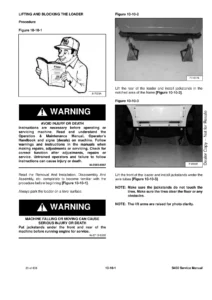
Skyjack SJIII 3220 3226 4620 4626 4632 DC Electric Scissor Lift Service Manual - 157928AP 2025 PDF β€” PDF page 1 preview
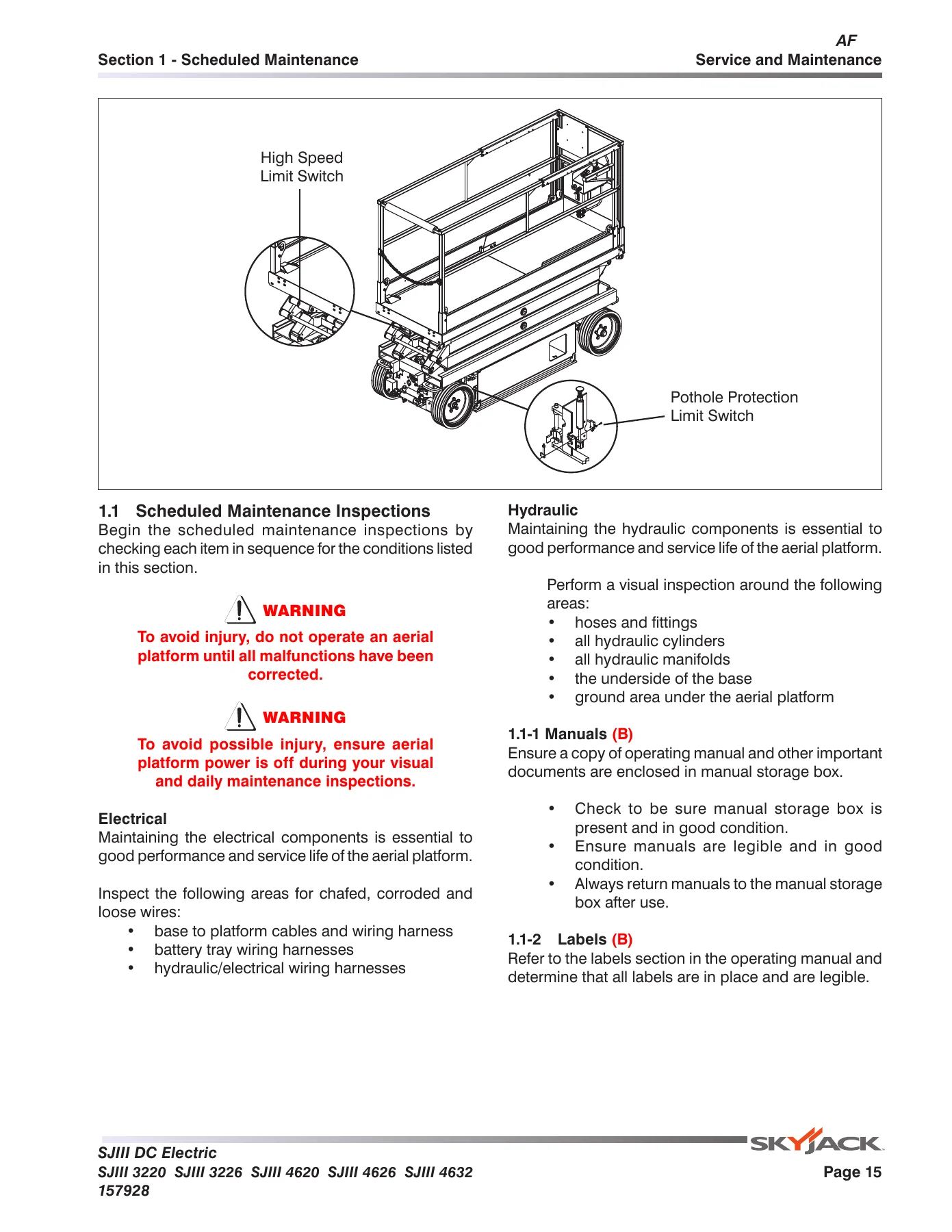
Skyjack SJIII 3220 3226 4620 4626 4632 DC Electric Scissor Lift Service Manual - 157928AP 2025 PDF β€” PDF page 15 preview
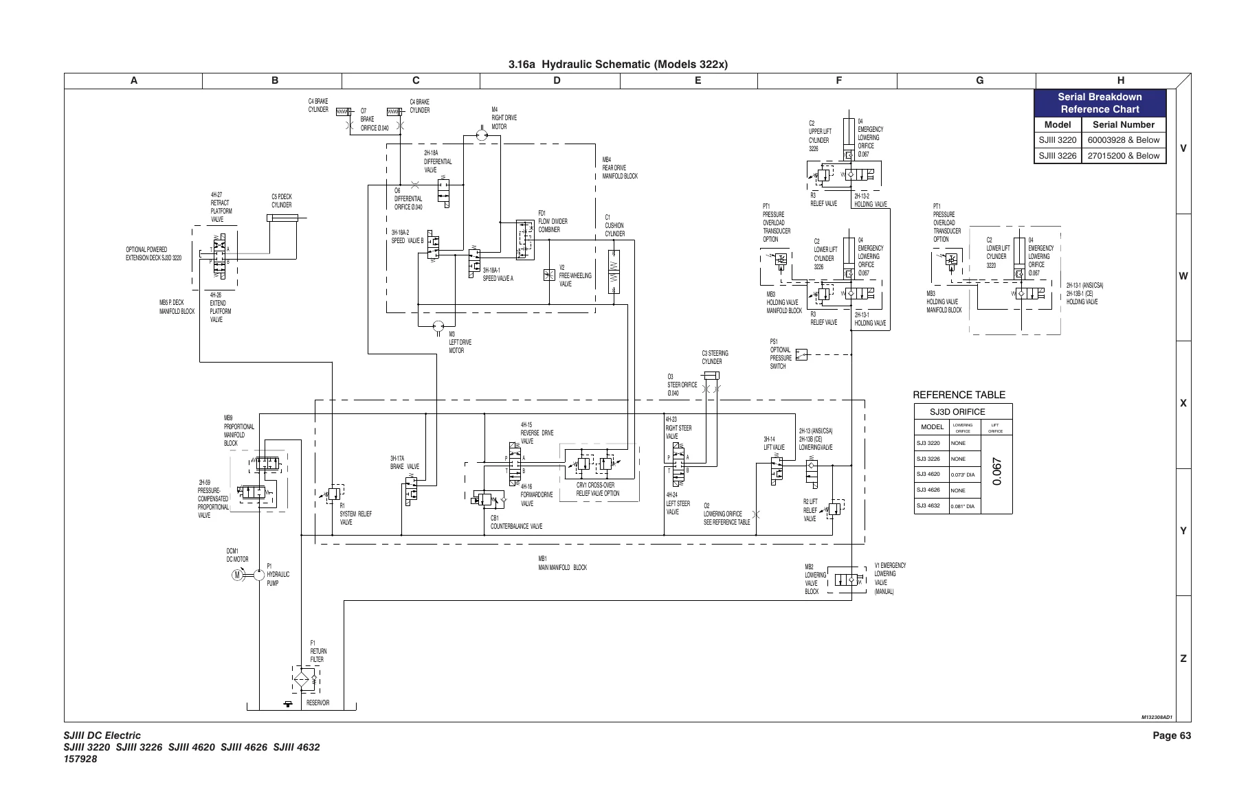
Skyjack SJIII 3220 3226 4620 4626 4632 DC Electric Scissor Lift Service Manual - 157928AP 2025 PDF β€” PDF page 63 preview

The file is delivered instantly as a downloadable PDF after checkout – no shipping, no waiting. Open it on any device, print the pages you need for the shop floor, and keep the full manual available for reference whenever a fault code or a scheduled inspection comes up.

Reviews

There are no reviews yet.

Be the first to review “Skyjack SJIII 3220 3226 4620 4626 4632 DC Electric Scissor Lift Service Manual – 157928AP 2025 PDF”

What Our Customers Say

β˜…β˜…β˜…β˜…β˜… Live reviews from customers
Loading customer reviews...
0
    0
    Your Cart
    Your cart is emptyReturn to Shop
    πŸ›’
    Recently Purchased
    πŸ•’ verified order