SonoScape S22 Series Ultrasound Service Manual PDF
Original price was: $65.00.$15.95Current price is: $15.95.
This SonoScape S22 service manual PDF (P/N 4720.00080A01, August 2014) provides safety guidelines, unpacking/system checks, principle descriptions, parts disassembly, and wiring details for the S22 ultrasound. Includes troubleshooting, adjustments for hardware like probe board, VBF board, power supply, and maintenance procedures.
Description
SonoScape S22 Series Ultrasound Service Manual PDF DOWNLOAD
Description
Explore the official SonoScape S22 Series ultrasound service manual PDF, a comprehensive resource for technicians maintaining this advanced diagnostic system. Published by SonoScape Co., Ltd. in 2014 (P/N 4720.00080A01), it covers essential topics like safety precautions (electrical, mechanical, biohazards), acoustic power principles (ALARA, indices), unpacking/assembly, system checks (functional, mechanical, image tests for B/THI/Color/PW/3D/4D modes), hardware/software principles, disassembly of components (LCD monitor, keyboard, touch screen, main board, hard disk, power supply, battery), and detailed wiring descriptions with pin connections for cables like speaker, footswitch, SATA, DVI, USB, and more.
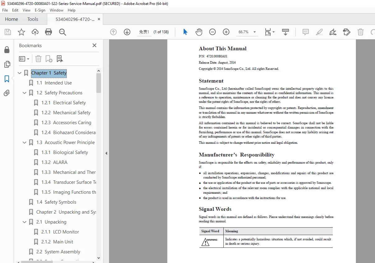
The manual lacks embedded bookmarks but includes a detailed contents section on pages 3-5, extracted below in bullet points:
- Chapter 1 Safety
- 1.1 Intended Use
- 1.2 Safety Precautions
- 1.2.1 Electrical Safety
- 1.2.2 Mechanical Safety
- 1.2.3 Accessories Caring
- 1.2.4 Biohazard Considerations
- 1.3 Acoustic Power Principle
- 1.3.1 Biological Safety
- 1.3.2 ALARA
- 1.3.3 Mechanical and Thermal Indices
- 1.3.4 Transducer Surface Temperature Limits
- 1.3.5 Imaging Functions that Change Acoustic Output
- 1.4 Safety Symbols
- Chapter 2 Unpacking and System Checks
- 2.1 Unpacking
- 2.1.1 LCD Monitor
- 2.1.2 Main Unit
- 2.2 System Assembly
- 2.3 System Connection
- 2.4 Power On/Off
- 2.5 System Checks
- 2.5.1 Unpacking Checks
- 2.5.2 General Checks
- 2.5.2.1 Overview
- 2.5.2.2 Operating Environment
- 2.5.2.3 System Configuration
- 2.5.3 Functional Checks
- 2.5.3.1 Workflow
- 2.5.3.2 Checklist
- 2.5.4 Mechanical Checks
- 2.5.5 Image Tests
- 2.5.5.1 B Image Test
- 2.5.5.2 THI Image Test
- 2.5.5.3 Color/DPI/TDI Image Test
- 2.5.5.4 PW/CW Image Test
- 2.5.5.5 3D Image Test
- 2.5.5.6 4D Image Test
- 2.1 Unpacking
- Chapter 3 Principle Descriptions
- 3.1 System Block Diagram
- 3.2 Hardware Description
- 3.2.1 Probe Board
- 3.2.2 VBF Board
- 3.2.3 High-Voltage Board
- 3.2.4 Industrial Main Board
- 3.2.5 DVI Conversion Board
- 3.2.6 Internal IO Board
- 3.2.7 KEAA Board
- 3.2.8 Touch-Screen Control Board
- 3.2.9 Display Interface Board
- 3.2.10 Keyboard Unit
- 3.2.11 Power Supply Unit
- 3.3 Software Description
- 3.3.1 Structure
- 3.3.2 Workflow
- Chapter 4 Parts Disassembly
- 4.1 LCD Monitor Base
- 4.2 Monitor Arm
- 4.3 LCD Monitor
- 4.4 Keyboard
- 4.5 Touch Screen
- 4.6 Ultrasound Unit
- 4.7 DVD Drive
- 4.8 Main Board
- 4.9 Hard Disk
- 4.10 Power Supply
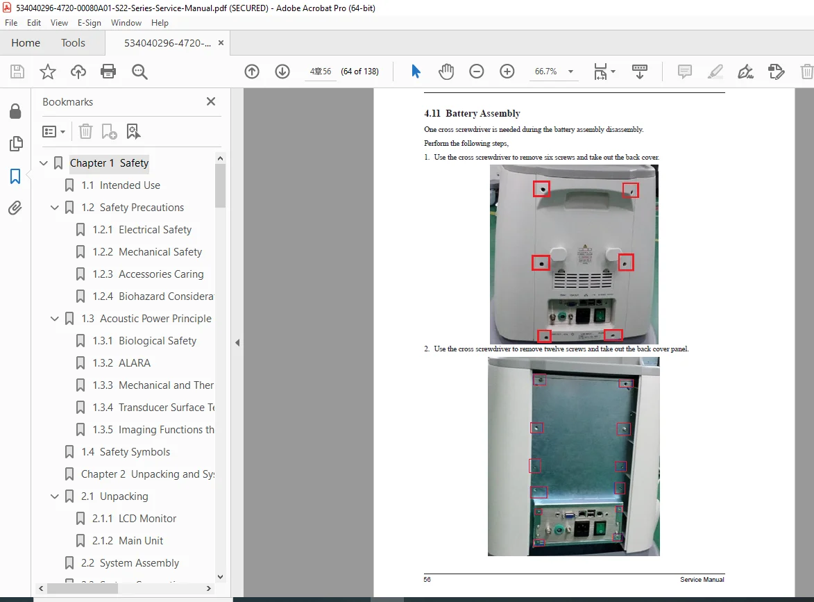
- 4.11 Battery Assembly
- Chapter 5 Wiring Descriptions
- 5.1 Concerns for Wiring
- 5.2 Pin Connection
- 5.2.1 Speaker Connection Cable
- 5.2.2 Footswitch Signal Cable
- 5.2.3 SATA DVD-RW Power Cable
- 5.2.4 SATA Signal Cable
- 5.2.5 Switching Mode Power Supply Input Cable
- 5.2.6 Keyboard Transmission Cable
- 5.2.7 Trackball Signal Cable
- 5.2.8 Display Grounding Cable
- 5.2.9 TGC Board Signal Cable
- 5.2.10 AM1808 Board USB Signal Cable
- 5.2.11 Rear Panel Power Cable
- 5.2.12 PS2 Control Cable
- 5.2.13 Audio Output Cable
- 5.2.14 Main Board – External IO Board DVI Cable
- 5.2.15 Display DVI Signal Cable
- 5.2.16 Display Power Cable
- 5.2.17 Display Power Conversion Cable
- 5.2.18 AM1808 Board Signal Cable
- 5.2.19 Dual USB Transmission Cable
- 5.2.20 BNC Signal Cable
- 5.2.21 Print Remote Transmission Cable
- 5.2.22 ECG Built-in Lead Wire
- 5.2.23 Pencil Probe Signal Cable
- 5.2.24 Charging Management Power Input Cable
- 5.2.25 Charging Management Power Output Cable
- 5.2.26 Charging Management Board – Battery Conversion Board Cable
- 5.2.27 Charging Management Board-Startup LED Indicator Board Cable
This SonoScape S22 Series ultrasound service manual PDF emphasizes biohazard safety, ALARA principles, and step-by-step disassembly/wiring for reliable repairs. Note: No formal index beyond contents; manual is for in vitro diagnostic use only.
File Details
- Manual Name: Service Manual for S22 Series (P/N 4720.00080A01)
- Models Covered: S22 Series
- Year: 2014 (Release Date: August 2014)
- Manual PDF Quality: High-quality professional document with clear text, diagrams, tables, and photos
- No. of Pages: 138