
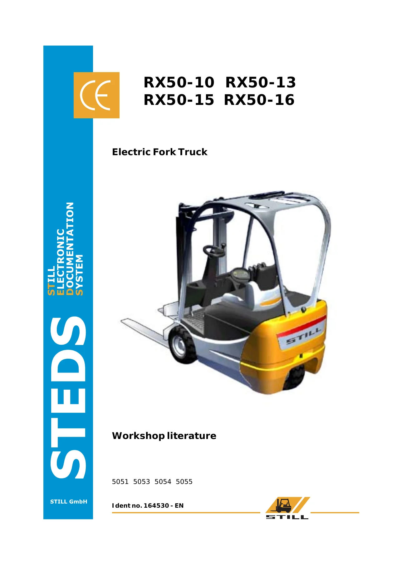
STILL RX50-10 RX50-13 RX50-15 RX50-16 Electric Fork Truck Workshop Manual – Ident 164530
Original price was: $39.95.$24.95Current price is: $24.95.
Complete STILL workshop manual for the RX50-10, RX50-13, RX50-15 and RX50-16 electric fork trucks (workshop literature 5051 / 5053 / 5054 / 5055, Ident no. 164530). Covers the asynchronous traction motor, power unit, steering, brakes, hydraulics, mast, electrical and electronic systems, converter and pump regulator.
Description
STILL RX50 Electric Fork Truck Workshop Manual – Ident 164530
This is the workshop manual released for the STILL RX50-10, RX50-13, RX50-15 and RX50-16 electric fork trucks, published as workshop literature 5051 / 5053 / 5054 / 5055 under Ident no. 164530 (EN). The 04.03.2005 edition was completely revised to reflect the generation 5 converter now fitted to the series, and it also documents the earlier generation 3 converter so both build phases are covered.
Rather than a driver’s booklet or a generic material-handling guide, this is the bench-level document a technician works from: it takes each assembly apart, states the tightening torques and adjustment values as they are printed, and puts it back together. Hydraulic and electrical schematics are included so that faults can be traced rather than guessed at.
File Details
- Manual type: Workshop manual / workshop literature
- Brand: STILL
- Models covered: RX50-10, RX50-13, RX50-15, RX50-16
- Product line: Electric fork truck
- Ident no.: 164530 – EN
- Workshop literature numbers: 5051, 5053, 5054, 5055
- Edition note: 04.03.2005 – completely revised output, generation 5 converter
- Language: English
- Page count: 204
- File format: PDF
Chapters Covered
- 00 Product information
- Safety instructions
- Use jack to lift truck on counterweight
- Use jack to lift truck on mast
- 11 Electrical motor
- General technical data
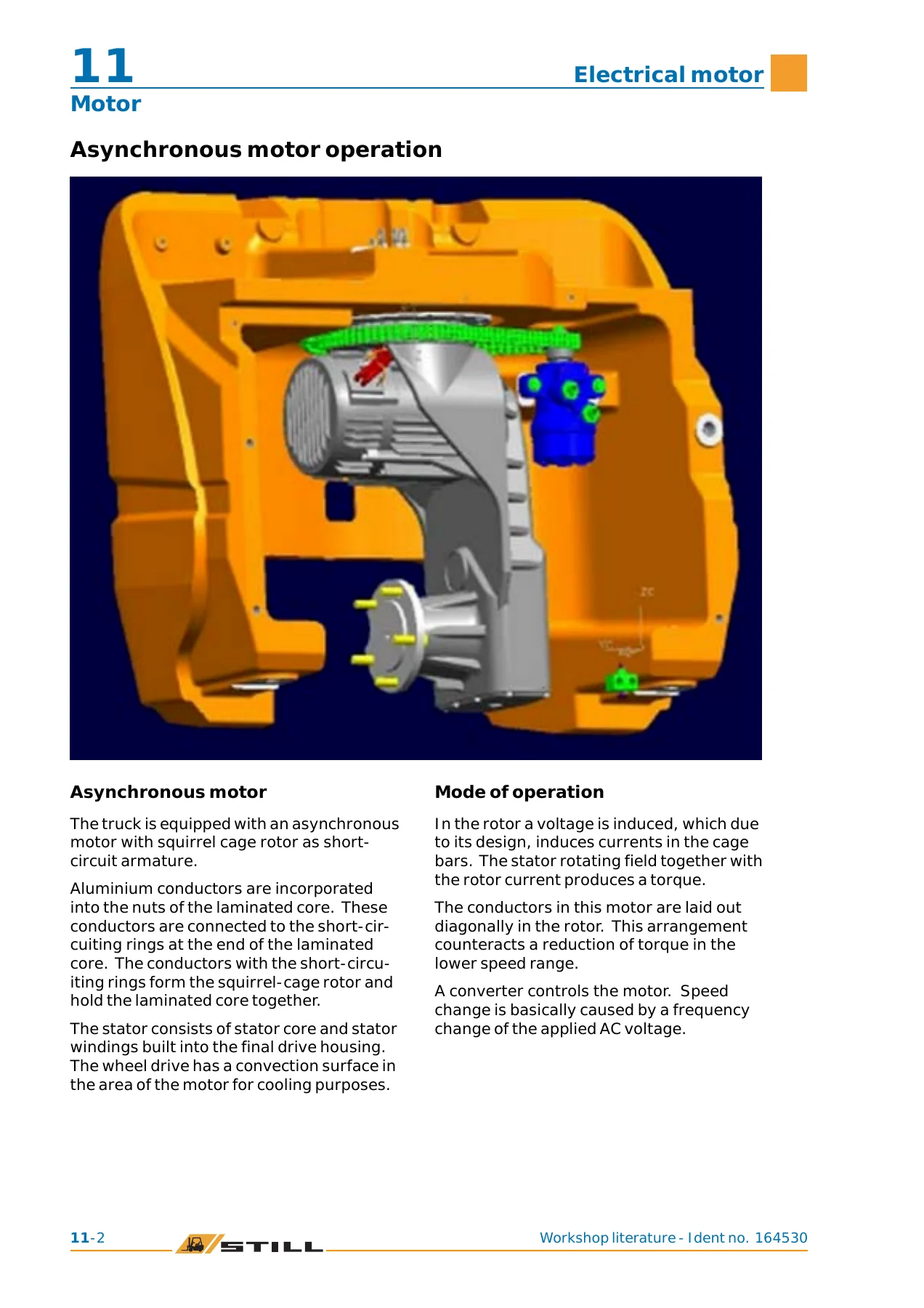
- Asynchronous motor operation
- Electrical connections
- Motor rotor disassembly / assembly
- Speed sensor and speed sensor bearing
- Motor temperature sensor
- 22 Mechanical drive axle
- Wheel hub removal, sealing and installation
- Power unit – general technical data
- Power unit disassembly / installation
- 34 Driver’s compartment
- Driver’s seat
- Seat contact switch
- Seatbelt lock switch
- 42 Steering system
- Hydraulic steering – general technical data
- Steer motor removal / installation
- Chain wheel with sensor wheel
- Steering unit
- Membrane pressure switch
- Priority valve
- Steering-angle-dependent performance (CSC)
- Steering angle neutral switch
- Steering angle sensor
- Steering wheel with steering column
- 46 Wheels and tires
- Complete wheel assembly – general technical data
- Wheels and tires
- Wheel bearing / hub
- 49 Brake system
- Hydraulic service brake – general technical data
- Brake shoes
- Main brake cylinder
- Wheel brake cylinder
- Brake sensor
- Brake fluid switch
- Parking brake and parking brake switch
- 50 Operational controls
- Single-pedal accelerator
- Twin-pedal / two-pedal accelerator
- Lock switch
- Emergency switch
- 56 Indicator elements
- Operator control panel / keypad
- Mini console
- Display and control panel
- Programming mode and password levels
- Discharge indicator
- 60 Electrical system / electronic system
- General technical data
- Device code and read options
- Block diagram
- Insulation test
- Electrical installation and CAN bus connections
- Electrical components and auxiliary installation
- Control unit (vo) complete
- Fuses, contactor, warning system, horn
- Battery, battery plug, roller platform
- Rear distributor board and forward distributor plate
- Relay board
- 64 Electrical controls
- Drive and operating hydraulics controller
- Control computer
- Pump regulator – replacement
- Converter – generation 5 drive converter
- Converter – generation 3 drive converter
- 70 Hydraulics
- Hydraulics general – general technical data
- Working speeds for lifting, lowering and tilting
- Safety checks (forward tilt, lowering, hose assembly)
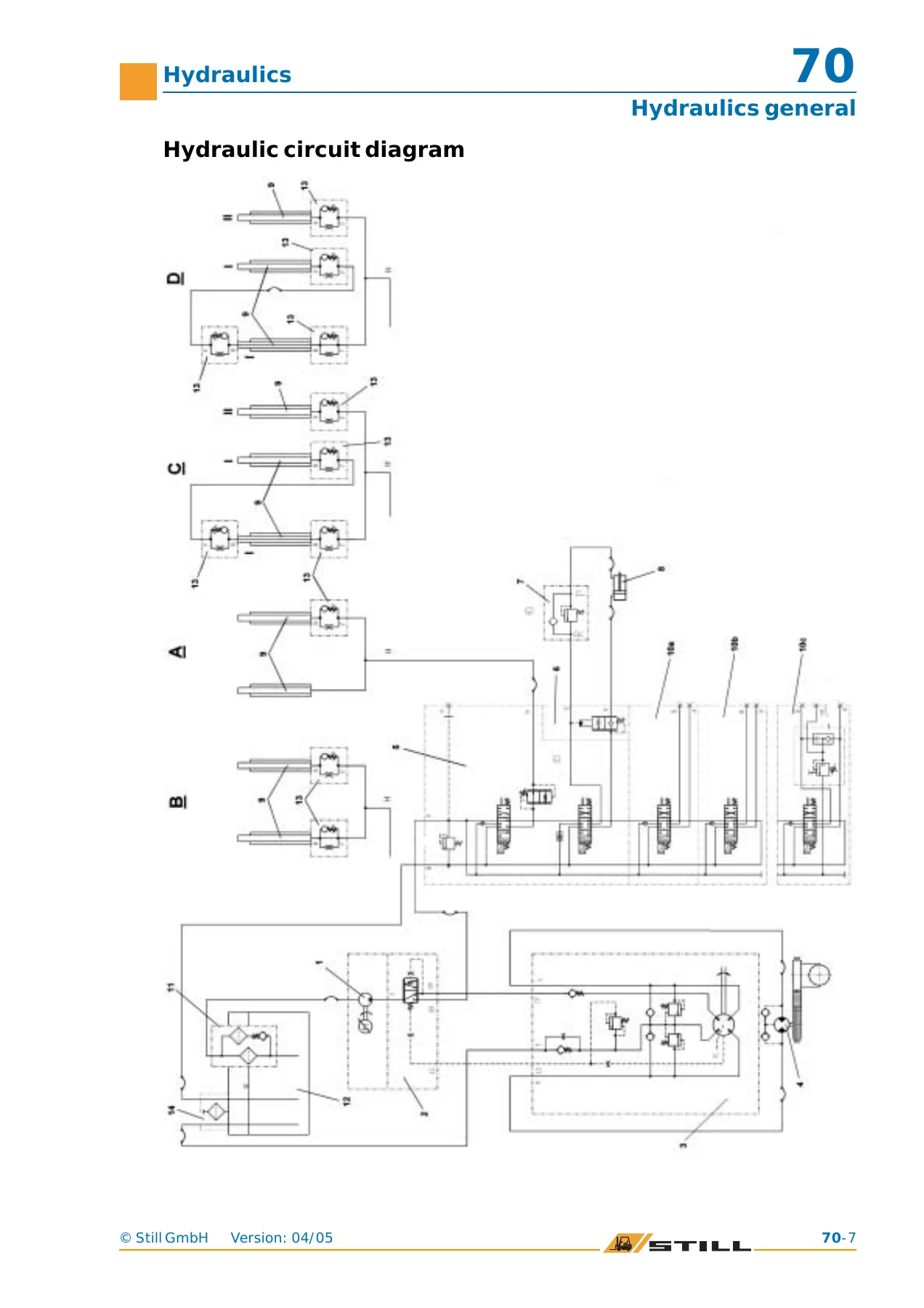
- Hydraulic installation and circuit diagram
- Base hydraulics – hydraulic tank, intake filter
- Conical nipple fittings (CNF), breather filter, bolted joint
- 71 Working hydraulics
- Pump assembly and pump motor
- Pump motor speed sensor and temperature sensor
- Brush monitoring unit and carbon brushes
- Hydraulic pump
- Combination lever actuation
- Tilt cylinder and tilt cylinder seal kit
- Additional hydraulics and hose line on mast
- 76 Valves
- Valve block and directional control valve arrangement
- Directional control valve function
- Hydraulic sensor
- Pressure regulator
- Tilt restrictor
- 81 Mast
- General technical data and mast weights
- Telescopic mast, Nihomast, Triplex mast
- Mast removal and installation
- Chains – outer, triplex outer and centre lift chains
- End position damping (outer and centre cylinder)
- Hose safety valve and installation positions
- Lift cylinder, centre cylinder, outer cylinder
- Rollers and supporting rollers
- 84 Load carrier
- Fork carriage
What ties these chapters together is a single working method rather than a pile of facts. The manual opens with the lifting and jacking precautions the truck requires, then moves through the traction side of the machine – the asynchronous motor, its squirrel-cage rotor, sensor bearing and temperature sensor – into the power unit that carries both the motor and the drive wheel. From there it works forward through the driver’s compartment, the hydraulic steering with its orbitrol, steer motor and chain, and into the brake system with its hydraulic service brake and cable-actuated parking brake.
The electrical side is treated with the same depth. The control computer, pump regulator and drive converter each get their own treatment, including removal and installation, LED status interpretation, overtemperature behaviour, precharging of the intermediate circuit and the safe discharge of the internal backup capacitors before the converter is pulled. CAN bus wiring, the magnetic ring core used on the converter harness, fuse allocation, the forward distributor plate and rear distributor board are all set out so an electrical fault can be narrowed down systematically. The insulation test procedure is written out with the required test voltages and minimum values, and the warning that motor temperature sensors must be bypassed before testing.
On the hydraulic side, the manual covers the gear pump, priority valve, directional control valve block, lift and tilt cylinders, the lowering brake and the hose failure valves. Flow restrictor sizing for tilting is tied to rated lift height, and the pump motor speed settings are given for lift, tilt, steering and the additional hydraulic functions. Tilt cylinder resealing, mast chain adjustment with the 2 mm clearance to the coasting block, support roller replacement and the mast bearing torque are all presented as step-by-step procedures rather than summaries.
What This Workshop Manual Lets You Do
With the STILL RX50-10, RX50-13, RX50-15 and RX50-16 electric fork truck workshop manual in front of you, the jobs that normally mean calling a dealer become jobs you can schedule yourself. Removing and refitting the traction motor rotor, replacing the FAG speed sensor bearing, resealing the tilt cylinder, changing brake shoes and readjusting the parking brake, replacing the pump regulator or the drive converter, setting the steering angle sensor air gap and calibrating it through the control computer – all of these are covered with the values you need to do them correctly.
The specifications matter as much as the procedures. A wheel hub fastening screw at the wrong torque, a mast chain adjusted without the required clearance, a brake sensor left outside its valid voltage window, or a converter reinstalled without the correct heat transfer compound and screw torques will all come back as faults. This manual states those numbers as STILL published them, so the work is done to the manufacturer’s figures instead of to an estimate.
IMAGES PREVIEW
Instant PDF Delivery
The manual is delivered as a downloadable PDF immediately after checkout. There is no physical shipment and nothing to wait for – the file opens on a laptop, tablet or phone in the workshop, and any page or diagram can be printed and taken to the truck. Keep it on a shop computer for reference or on a device at the machine; either way the full 204-page document stays with you.
Reviews
There are no reviews yet.