
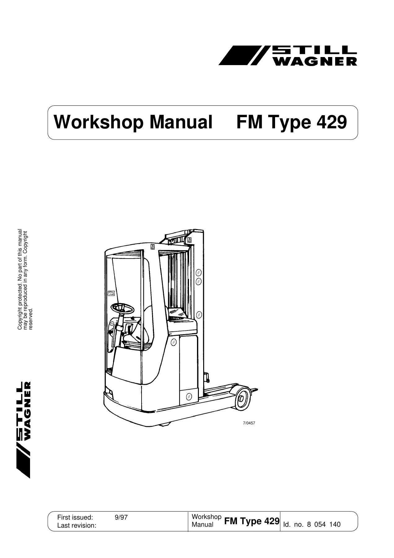
Still Wagner FM Type 429 Workshop Manual – FM 14, FM 17, FM 20 Repair PDF
Original price was: $36.95.$22.95Current price is: $22.95.
Complete Still Wagner FM Type 429 workshop manual covering the FM 14, FM 17 and FM 20 electric trucks built with the 1997 travel and pump control system. Travel motor, steering, brakes, FPS electrical system, hydraulics and lubrication plan in one 207-page PDF.
Description
File Details
- Manual type: Workshop manual (workshop service and repair documentation)
- Brand / publisher: STILL WAGNER GMBH & CO KG, Trainingszentrum, Ernst-Wagner-Weg 1-5, 72766 Reutlingen-Mittelstadt
- Model / type: FM Type 429 (FM group)
- Covered vehicles: FM 14, FM 17, FM 20
- Issue: 9/97
- Language: English
- File format: PDF
- Page count: 207 pages
What This Still Wagner FM Type 429 Workshop Manual Covers
This is the workshop documentation for the FM Type 429 trucks fitted with the new travel and pump control system introduced in 1997. The manual is split into numbered assemblies, each carrying its own sheet numbering (A, B, C, M, N and R), and it is written for the technician working on the vehicle rather than for the operator.
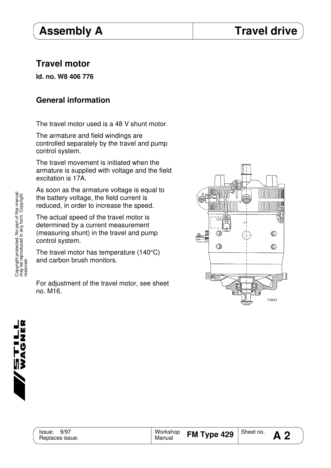
Assembly A – Motor and Travel Drive
- Motor, general
- Terminal markings at the motor (A1, A2, F1, F2, X15 sensor terminals)
- Exchanging the carbon brushes
- Checking the brush springs
- Changing the drive wheel (complete)
- Removing the travel drive system
- Commissioning the gearbox after exchange
- Oil change, gearbox
Assembly B – Steering
- Structure of the steering system
- Functional characteristics of the steering sensor and magnetoresistor
- Slipring system
- Removing and mounting the steering column
- Setting the steering sensor (mounted and unmounted condition)
- Servo unit – general and terminal coding
- Exchanging the carbon brushes in the steering servo motor
- Removing the servo unit
- Steering transmission, chain wheels and deep-groove ball bearings
- Chain tensioning – steering chain and steering transmission chain
- Exchanging the steering chain
- Steering controller – block diagram, functional characteristics and safety monitoring
- Setting the steering controller (P1 balance, P2 amplification, P3 dead zone)
Assembly C – Brake
- Functional characteristics of the hydraulic/mechanical brake system
- Plan of hydraulic brakes with and without load wheel brake
- Travel motor brake – mounting and removal
- Setting the brake clearance and checking brake lining thickness
- Setting the handbrake
- Setting the brake pedal and snifter clearance
- Braking distances
- Measuring the brake deceleration with the dynometer
- Main brake cylinder – general, special bottom valve and removal
- Bleeding and filling the brake system
Assembly M – Electrical System
- Traction and pump controller (FPS) – general and guide to components
- Main current and control current terminals
- Block diagram
- Logic circuit board – general and removal
- Electronic evaluation system (AWE) – general and removal
- Travel/hydraulics output stages and DC/DC converter
- Control of the travel motor and the main current circuit for travel, generator braking and hydraulics
- Safety circuit, anti-roll monitor and description of errors (FE01 to FE43)
- Control signals for travel (Vmax and 2.5 km/h) and for hydraulics
- Superconsole notebook software – installation and working with the software
- Electronic evaluation system control of the hydraulic system, block diagrams and truth table
- Simultaneous movements, compulsory reset and shift damper function
- Hydraulic options (lift cut-out, shifting and lowering lock, additional hydraulics)
- Control of the console display, battery charge level and software version display
- Error list and maintenance intervals
- TEWAK interface software and diagnosis/commissioning software
- Setting the battery discharge characteristic curve
- Guide to pin assignment and interface adapter
Assembly N – Hydraulic System
- Functional characteristics and block diagram of the hydraulic system
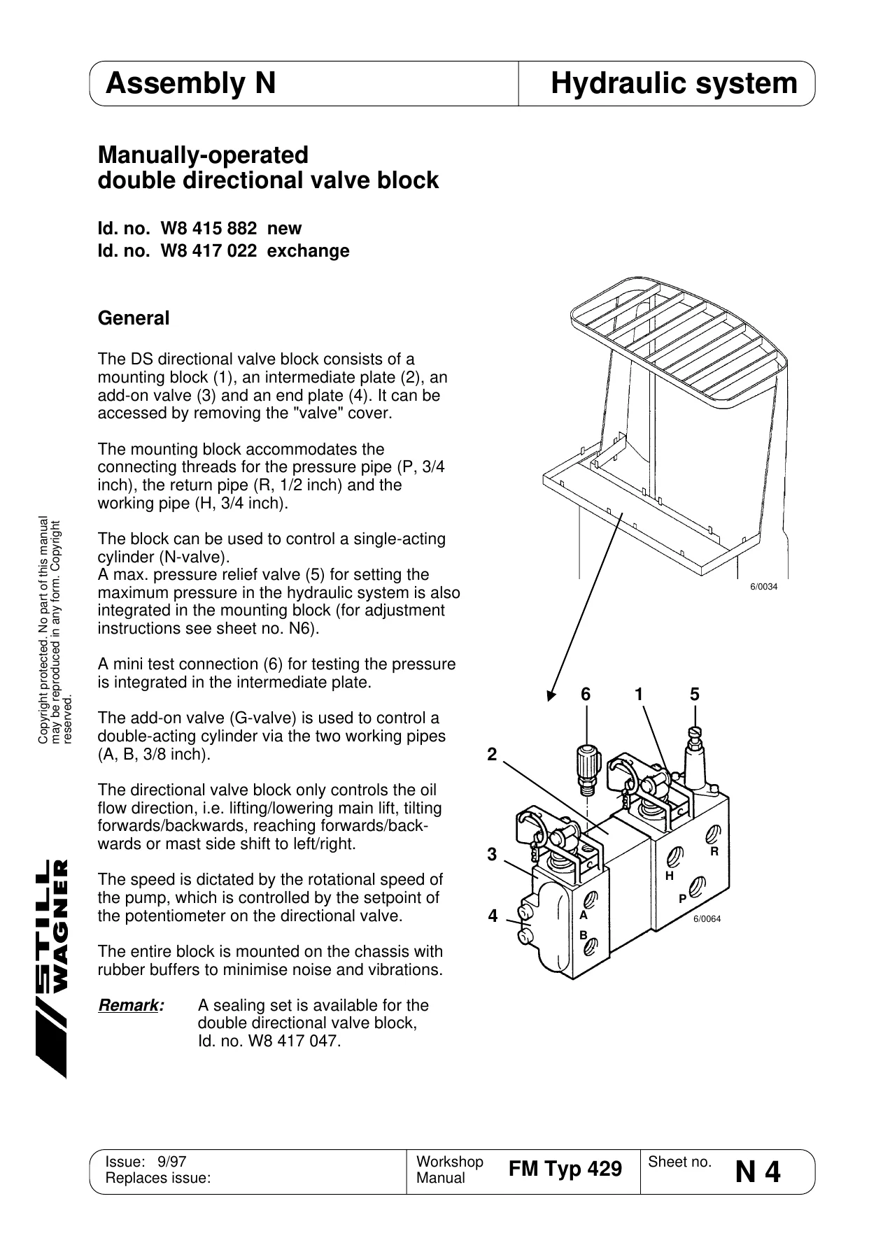
- Manually-operated double directional valve block and its designation
- Setting the maximum pressure
- 2-way flow regulator valve
- Directly operated directional valves – shift function 2Y25, tilting and mast side shift 2Y29/44
- Back-pressure valve for tilting (SBV)
- Tilting diaphragm
- Lowering brake valve
- Line break protection
- Pump unit – general and removal
- Pump motor – general, removal, carbon brushes and maintenance
- Hydraulic pump
- Tank display and tank
- Runback filter
- Pump motor specifications
Assembly R – Lubrication Plan
- Lubrication plan
- Lubricants and Id. numbers
- Lubrication card
- Decommissioning and disposal notes
How This Manual Supports the Job
The document is built around real procedures rather than theory. Every section that involves dismantling work gives a numbered sequence – pull the battery plug, remove the covers, release the fastening screws, lift the component clear – and the values you need to put it back together again. Where a setting matters, the manual states it: brake clearance between 0.3 and 0.5 mm, drive wheel nuts tightened in diagonal sequence to 140 Nm, a field excitation of 17 A at the travel motor, a steering lock of 95 degrees to either side, a maximum steering current of 30 A, a gearbox oil quantity of approximately 3.6 l with a ratio of i = 15.93, a hydraulic system pressure set at 200 bar and a back-pressure valve for tilting preset to 120 bar.
The electrical material is where this FM Type 429 workshop manual really earns its place on the bench. The traction and pump controller uses MOSFET output stages timed at 16 kHz with pulse width modulation, and the manual explains how the armature and field of the shunt-wound travel motor are controlled separately, how generator braking feeds power back to the battery, and how the anti-roll monitor pulses the field to detect movement. The safety monitoring section lists each condition under which the controller cuts out – overvoltage above 75 V, undervoltage below 12 V, short circuit, a heat sink temperature of around 100 degrees Celsius, reverse polarity – and the error description tables map each message to its likely cause and the remedy, so a fault code on the console display leads somewhere useful instead of dead ending.
Because the FPS and the electronic evaluation system are parameterised rather than fixed, the manual also documents the software side. There are instructions for installing and using the Superconsole notebook software, for reading and altering parameters, for saving and restoring parameter sets against a customer name, for checking signals in the tester menu, and for adapting the travel potentiometer through the PROGRAM VACC function. The electronic evaluation system menus – Configuration, Commissioning, Parameters, Error list and Maintenance interval – are walked through step by step, including how to set the battery discharge characteristic curve from the ancillary movements lever and selection keys.
Hydraulics, Brakes and Steering in Detail
On the hydraulic side the manual describes the manually-operated double directional valve block and how its designation is read, then works through the individual cartridges: the 2-way flow regulator valve that keeps simultaneous lift and reach movements under control, the directly operated directional valves for shifting, tilting and mast side shift, the tilting diaphragm that limits tilting speed according to load carriage height, the lowering brake valve that holds the lowering speed at a constant regardless of load, and the line break protection with its table of valve types and gap widths for each mast. The pump unit section covers the self-ventilated 48 V series-wound pump motor, the externally toothed gear pump, the capstan coupling, and the correct sequence for removal and recommissioning, including filling the pump with oil before mounting and venting the pressure connection on first start-up.
Brake work is covered from both ends: the travel motor brake that the handbrake acts on, and the service brake applied through the main brake cylinder. The manual explains the special bottom valve in the main brake cylinder, the throttling port that lets excess pressure fall to zero, and the one millimetre snifter clearance that has to be felt rather than seen. Bleeding and filling procedures are given in full, with the caution about brake fluid and the warning not to reuse fluid that has overflowed.
Steering is treated as its own system. The manual explains the electrical steering boost, the mechanical emergency steering that takes over if the boost fails, the magnetoresistive steering sensor with its one millimetre magnet gap and its 2.47 V centre value, the slipring supply to the rotating sensor, and the full setting procedure for the sensor both on and off the vehicle. There are also the practical jobs – removing the steering column, exchanging the servo unit, replacing and tensioning both the steering chain and the steering transmission chain.
Why This Workshop Manual Matters
An FM 14, FM 17 or FM 20 that has been in service since the late nineties has usually accumulated work that needs doing properly: carbon brushes at the end of their life, chain tension that has drifted, brake clearance that has opened up, a gearbox due for its oil, a steering sensor that needs resetting after a repair, or a controller throwing a fault code. Guessing at these jobs is expensive. The carbon brushes in the travel motor must be replaced as a complete set of four and the motor should not be run straight away under full load; the steering sensor must not be connected to the battery unless it is correctly set; the gearbox must not be overfilled or the seals will fail and the operating temperature will rise. This manual gives you the correct procedure and the correct value in each case.
IMAGES PREVIEW
Instant PDF Delivery
The manual is delivered as a PDF download immediately after payment. There is nothing to ship and nothing to wait for. Keep it on a laptop or tablet in the workshop, print the sheets you need for the job in front of you, or print the whole file and build your own binder – the page baselines and sheet numbers are printed on every page so a printed copy stays in the right order. Whether you are servicing one FM 14, maintaining a mixed fleet of FM 14, FM 17 and FM 20 trucks, or rebuilding a travel drive on the bench, this Still Wagner FM Type 429 workshop manual is the reference to work from.

Reviews
There are no reviews yet.