
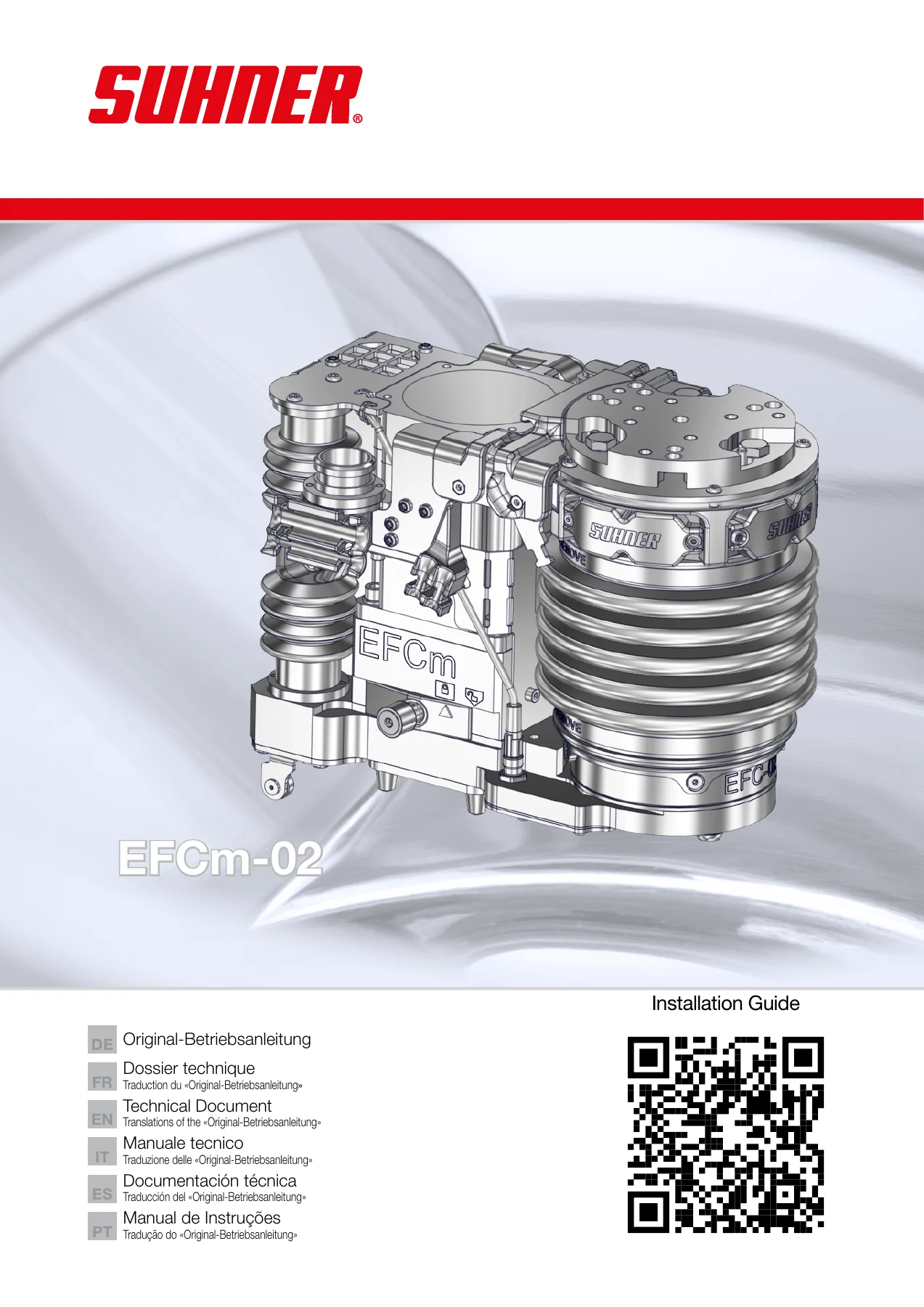
SUHNER EFCm-02 Power Hub Installation and Operation Manual – Technical Document PDF
Original price was: $29.95.$17.95Current price is: $17.95.
The complete multilingual installation guide and technical document for the SUHNER EFCm-02 Power Hub – mounting, wiring, web interface, Modbus TCP registers, calibration and maintenance for automated grinding and finishing cells.
Description
SUHNER EFCm-02 Power Hub Installation and Operation Manual
The SUHNER EFCm-02 Power Hub is the automated tool interface that drives modular SUHNER finishing heads inside robot cells and special-purpose machines. This SUHNER EFCm-02 Power Hub installation and operation manual is the original technical document issued with the unit, published across six languages so the same instructions can be followed on the shop floor regardless of region. It walks through adapter-plate mounting, cable routing, the embedded web interface, the Modbus TCP register map, force calibration and preventive maintenance intervals in enough detail to commission the unit and keep it running.
File Details
- Document type: Installation guide and technical document (Original-Betriebsanleitung with translations)
- Brand / manufacturer: SUHNER Schweiz AG, Industriestrasse 10, CH-5242 Lupfig
- Machine: EFCm-02 Power Hub (partly completed machinery)
- Languages: German, French, English, Italian, Spanish, Portuguese
- Page count: 108 pages
- File format: PDF
- Document date: 06/2024 (Declaration of Incorporation)
- Document agent: M. Maglione, Head of Solutions & Innovation
Chapters Covered
- Safety notes – general safety instructions, intended use, incorrect use, declaration of incorporation, integration into the emergency stop circuit
- Description – rating data, communication interface, control, RFID, operating conditions, storage, interfaces to the tool
- Rating data, torque limits Mx / My / Mz, IP protection class
- RFID position, belt-state sensor, tool-detection sensor, dust extraction connection
- Commissioning – safety instructions, assembly instructions, connecting the EFCm-02, manual assembly of modular tools, robot-guided tool change
- Adapter plate for 50 mm, 80 mm and 100 mm robot interfaces
- Mounting the adapter flange, cable connection, servo cable connection
- Dust extraction, purge air, earthing
- Handling / operation – safety instructions, web interface, communication through fieldbus (Modbus TCP), status LED, firmware
- Setup, Data EFC, Data Modular, Calibration, Head, Info
- Service states, error codes, operation modes
- Register values, bus multipliers, conversion formulas
- Service / maintenance – preventive maintenance, troubleshooting, repair, warranty, disposal and environmental compatibility
- Cleaning work, service intervals, service warning and alarm handling
Read as a whole, this EFCm-02 technical document is unusually complete for a component of its class. Rather than a short leaflet, it behaves like a full integration dossier: mechanical drawings for the mounting flange appear alongside electrical pinouts, bus register tables and the exact sequence for a robot-guided tool change. A technician can take the unit from the shipping crate to a commissioned, networked axis without hunting for a second document, because the mechanical, electrical and software layers are all described in the same place.
What the Manual Covers in Practice
The rating data section establishes the working envelope before anything is bolted down: 48 VDC at connector X1 with a maximum input current of 1.0 A, a servo motor rated 200 to 480 VAC with up to 25 A input current, 2 kW output at S3 50 percent duty, a total stroke of 20 mm and a maximum axial target force of 200 N. Payload tops out at 8.5 kg with a unit weight of 10.8 kg before a tool is coupled, and the permissible moments are given as plus or minus 80 Nm on each of the Mx, My and Mz axes. Protection is IP54 once a tool is coupled and none at all when the unit is run bare, which the document states plainly rather than leaving the installer to infer it.
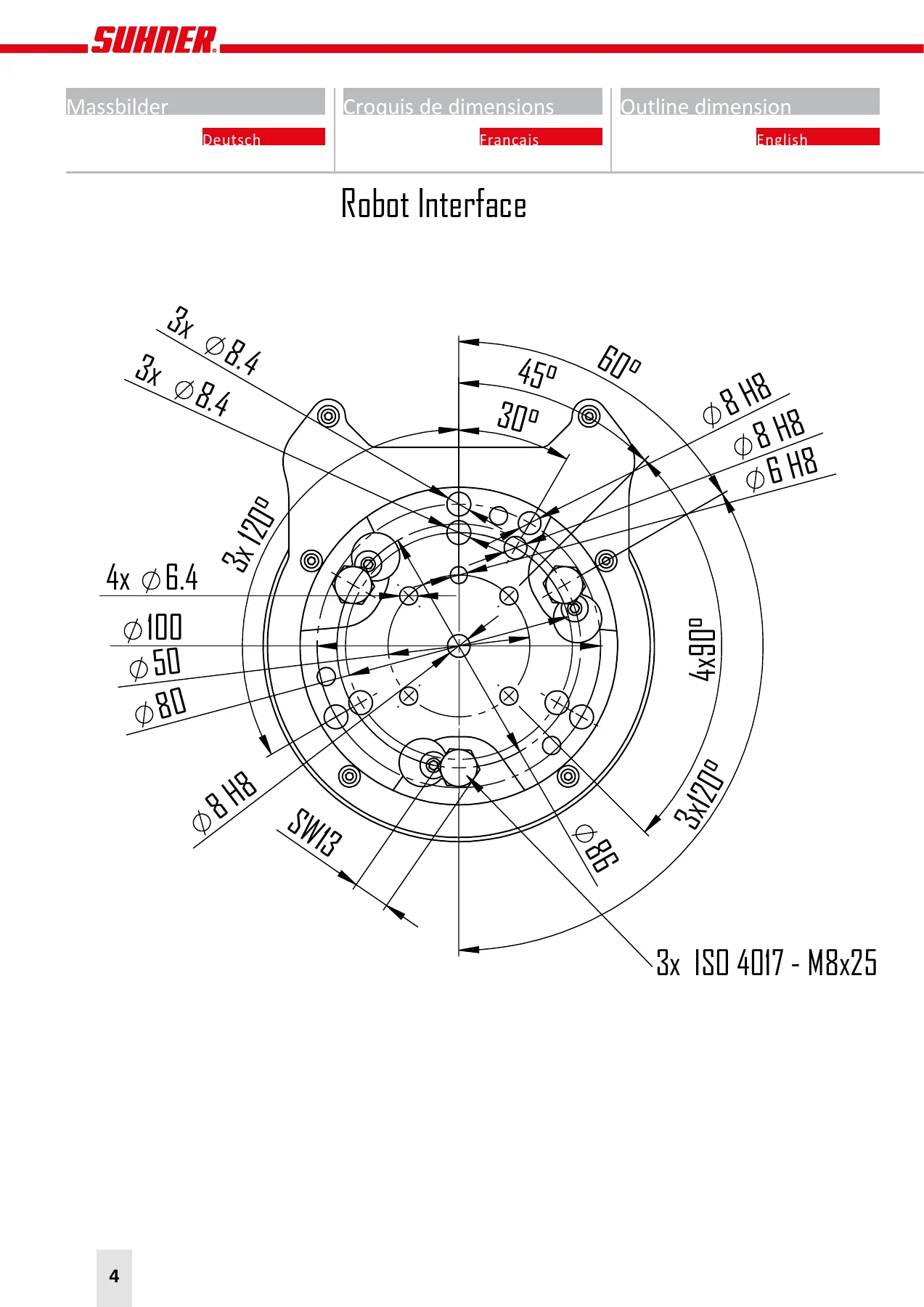
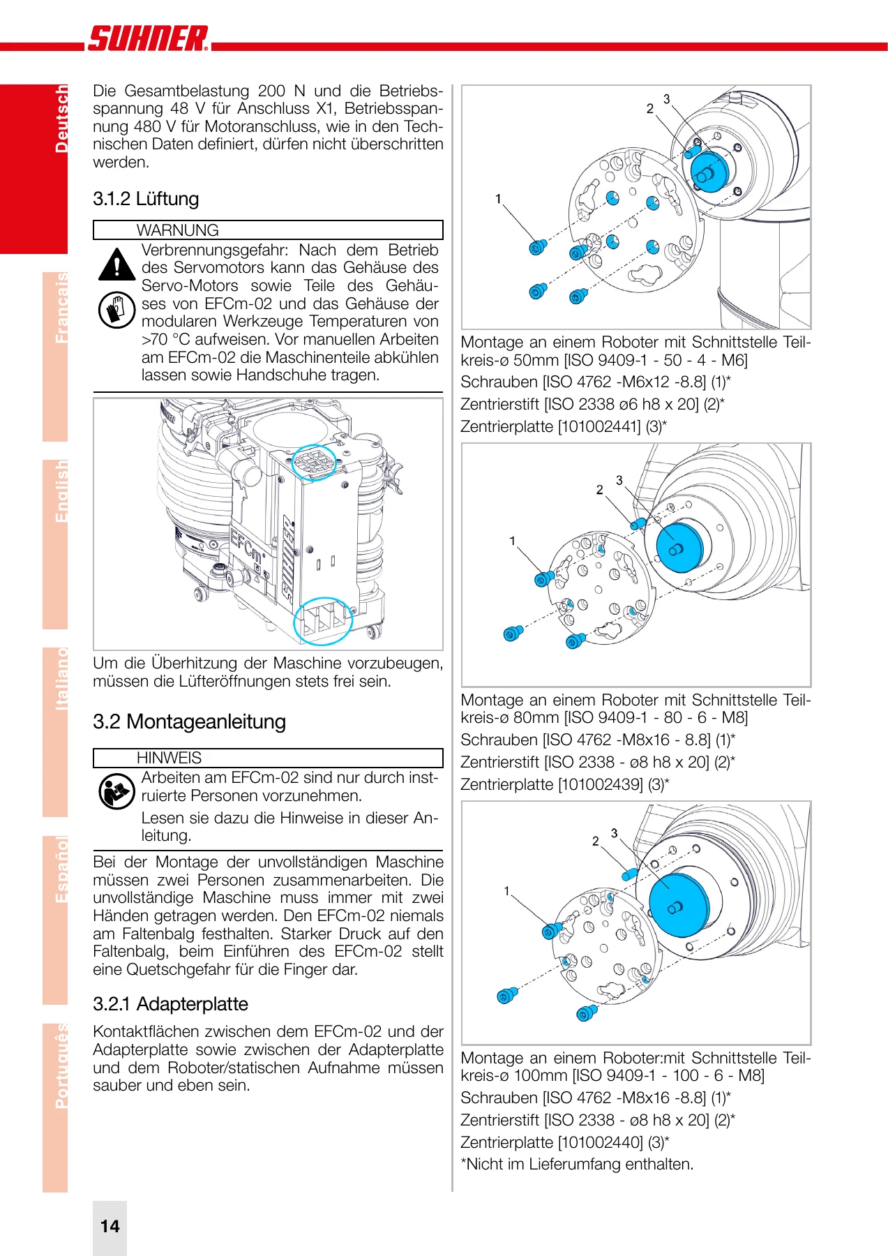
Commissioning guidance covers the three standard robot interfaces – 50 mm, 80 mm and 100 mm bolt circles to ISO 9409-1 – with the correct screw sizes, centering pins and centering plate part numbers for each. The adapter flange procedure is shown as a numbered pictorial sequence, as is the correct cable routing for the power, network and servo cables, including the warning that cables must not chafe against each other or any other part across the full stroke. Optional connections for dust extraction at a maximum of 200 mbar negative pressure, purge air through an M5 push-in fitting, and earthing via an M6x12 screw are each given their own section with a locating illustration.
The modular tool chapter is written with a clear safety emphasis, since a modular head can retract quickly and without warning into the EFCm-02. The manual specifies a two-person assembly routine – one person operating the coupling lever, the other guiding the head with both hands – and requires the lever to be checked against the closed-lock symbol before the tool is considered secured. Robot-guided tool changes through a docking station are referenced to the separate docking station instructions.
Web Interface, Fieldbus and Diagnostics
Two independent web interfaces are described: one for the EFC subsystem and one for Modular, distinguished on screen by frame colour. The document lists the factory IP addresses for each network participant – fieldbus coupler, IoT module, EFC, Modular and drive – and makes clear that these addresses must not be reused for the accessing device. Setup, Data, Calibration, Head and Info tabs are documented screen by screen, including which values may be written and which are reserved for SUHNER service.
For machine integration, the Modbus TCP chapter is the most directly useful part. It lists the implemented function codes, the register addresses for both subsystems, the multiplier applied to each value, the INT16 data type, and the two’s-complement formulas needed to send and receive negative values. Worked conversion examples are included so an integrator can verify a scaling calculation against the manual rather than against guesswork. A dedicated error code table maps each code to its message, description, movement behaviour and required action, and the operation mode table names each state the axis can be in.
Maintenance is scheduled rather than reactive: coupling cleaning every 40 operating hours, a service warning 200 hours ahead of the alarm, and a service interval at 3000 operating hours under load. The manual also states a hard 18-month service deadline that is not displayed by the system, which is exactly the kind of detail that gets missed when a machine sits idle for long periods.
Why This Document Matters
The EFCm-02 sits between a robot and a spinning abrasive head, and the document is written with that in mind. It defines the load limits that must not be exceeded, the emergency stop integration responsibilities that fall on the user, and the response expected when a subsystem reports a non-zero error code. Ignoring those boundaries risks damage to the robot, the workpiece, the EFCm-02 itself and any tool mounted to it.
On the practical side, this manual answers the questions that actually stop a commissioning: which screws and centering pins fit a 100 mm bolt circle, which cable goes to X1 versus X2 versus X3, how to convert a target force into a Modbus register value, why a LIMIT error was raised, and how long the unit can run before it needs attention. Having all of that in one place shortens installation and removes the guesswork from fault finding.
Ordering is instant. The PDF is delivered immediately after payment with no shipping and no waiting on a physical copy, and it can be read on a laptop, tablet or phone at the machine, or printed for the workshop binder. Keep it with the equipment documentation and hand it to whoever integrates or services the cell next.
IMAGES PREVIEW


Reviews
There are no reviews yet.