
Stryker Secure II Model 3002 Med-Surg Bed Maintenance Manual – 3002-009-002 Rev D
Original price was: $34.95.$19.95Current price is: $19.95.
Complete Stryker Secure II Model 3002 Med-Surg Bed maintenance manual (3002-009-002 Rev D). Covers base and litter teardown, CPU/power board diagnostics, Zoom drive option, scale and Bed Exit calibration, wiring, exploded assembly drawings and parts lists. Instant PDF download.
Description
File Details
- Manual Type: Maintenance Manual
- Brand: Stryker Medical
- Model: Secure II Model 3002 Med-Surg Bed
- Document Number: 3002-009-002
- Revision: Rev D
- Language: English
- Page Count: 265
- File Format: PDF
Chapters Covered
- Specifications, Weight Capacity, Dimensions and Electrical Requirements
- Warning / Caution / Note Definition and Safety Tips and Guidelines
- Limited Warranty, Obtaining Parts and Service, Service Contract Coverage, Return Authorization, Freight Damage Claims
- Set-Up Procedures — Standard Bed and Zoom Option
- Bed Symbols, Bed Illustration
- Bed Operation — Brake Pedal, Steer Pedal, CPR Emergency Release, Foot Prop, Fracture Frame, Foley Bag Hooks, Patient Restraint Strap Locations
- Night Light Usage, Nurse Call Back-Up Battery, 110V Outlet, CPR Board Usage
- I.V. Poles, Positioning Siderails, Siderail Control Panel Lights
- Siderail Function Guide, Foot Board Control Panel Guide, Weigh System Control Panel Guide, Weigh System Usage
- Pendant Controller, Zoom Option Drive Wheel Operation, Zoom Option Head End Control Panel Operation, Zoom Option Battery Charging and Operation
- Cleaning and Preventative Maintenance, Static Discharge Precautions
- Troubleshooting — Standard Bed and Zoom Option
- Bed Circuit Boards — CPU Board, Power Supply, Inverter/Charger Board, 2000 Option AC Crossover Board, Zoom Display/CPU Board, Optional Night Light Board
- Optional Bed Communications Tester, 37-Pin Connector Pinout, Stryker Pendant Port
- Headwall Output Configuration, CPU/Headwall Jumper Locations, Inverter Protection Features
- Replacement Parts Quick Reference
- Base Maintenance Procedures — Brake Pedal, Lift Motor and Capacitor, Lift Motor Isolation Plate, Lift Housing, Lift Potentiometer Replacement and Adjustment, Lift Potentiometer Burn-In, Lift Motor Coupler, Power and Sensor Coil Cord, Zoom Option Battery, Zoom Option Power Board
- Litter Maintenance Procedures — Knee Motor, Head Motor Cam and Cam Guide, Head Motor Limit Setting, Head Motor, Head Motor Drive Isolator and CPR Decoupler, Drive Screw and Ball Nut, Head Motor Brake/Clutch
- Scale System Diagnostics, Scale System Calibration, Load Cell Replacement, Power Supply Replacement, CPU Board Replacement, Potentiometer Burn-In, Smart TV Interface Burn-In
- Zoom Option Control Bar Potentiometer Replacement and Burn-In, Zoom Option AC Crossover Board Replacement, Zoom Option Display/CPU Board Replacement
- Siderail Cover Removal, Molded Siderail Replacement, Head End Siderail Cable Replacement, Siderail Assembly Removal
- Foot Board Hinge Removal, Foot Board Module Replacement, Foot Board Interface Plug Replacement
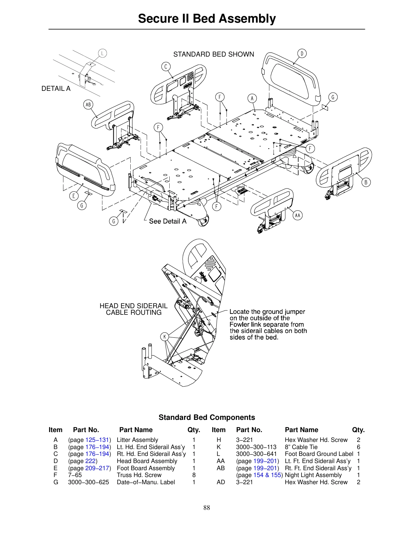
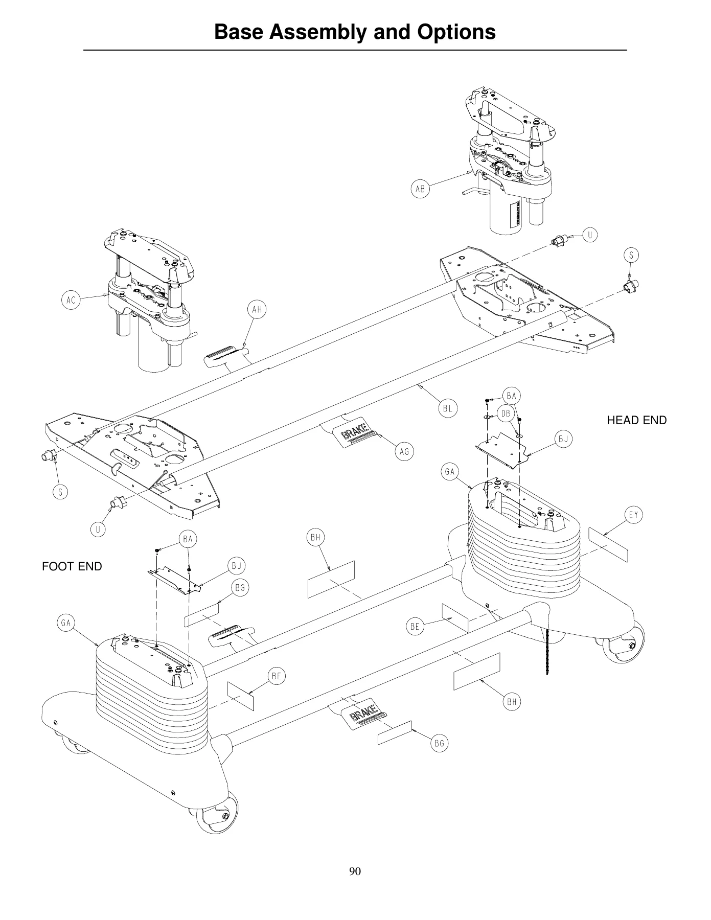
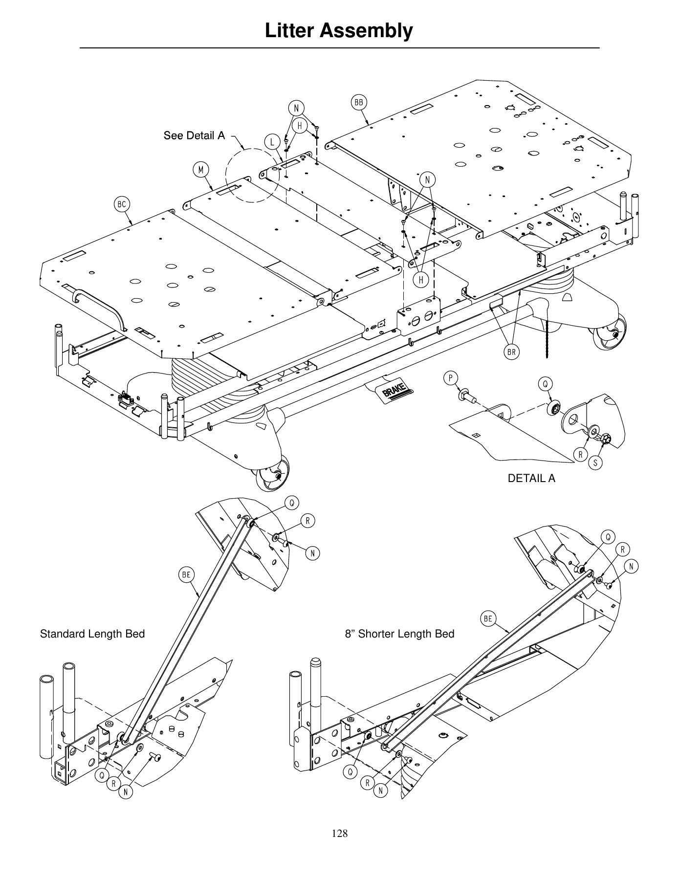
- Assembly Drawings and Parts Lists — Bed, Base and Options, Lift, Motor Isolation Plate, Brake Shaft, Brake Crank, Brake Bar, Caster, Zoom Base, Zoom Drive Wheel Lift Lever, Zoom Bottom Covers, Zoom Drive Train, Zoom Battery Tray, Zoom Base Power, Battery Back-Up Option Base, Litter, Litter Covers, Electrical Litter, Mechanical Litter, 230V Surge Suppressor, Lift Header, Gatch Motor, Fowler Drive, Fowler Limit Switch, Night Light, Optional 110V Outlet, 110V Outlet Box, Scale/Bed Exit Option, Optional HWI with Communication, Optional HWI with Communication and Ports
The Stryker Secure II Model 3002 Med-Surg Bed Maintenance Manual (3002-009-002 Rev D) is the field and shop reference for keeping a Secure II 3002 hospital bed in safe, code-compliant working order. Its 265 pages move logically from specifications and set-up through daily operation, then into full mechanical and electrical teardown for both the base and the litter, and finish with the detailed exploded assembly drawings and parts lists used to identify every fastener, bracket, bushing, circuit board and motor by part number. Because the Secure II was offered as a Standard Bed, Short Bed, Zoom Bed and Zoom Short Bed, the manual cross-references the correct procedures and part numbers for each configuration as the text moves through them, rather than assuming one bed layout.
What a Technician Actually Gets From It
Early sections cover the fundamentals you’d otherwise have to learn on the floor: how to set up the bed before it goes into service, how to verify that the brake-not-set LED, steer pedal, CPR release, foot prop, motion interrupt pan and siderail latches all behave, and how the weigh system must be zeroed before Bed Exit is armed. The Bed Operation chapter explains the patient-facing controls — brake pedal, steer pedal, CPR emergency release, foot prop, fracture frame, Foley bag hooks, restraint strap locations, night light, nurse call back-up battery, 110V outlet, CPR board and both I.V. pole styles — and then continues with the siderail function guide, foot board control panel guide and weigh system control panel guide, so any control that a nurse or technician presses can be traced to the right PCB header during fault-finding.
The Troubleshooting chapter is organised by symptom rather than by theory: no power to bed, no bed down motion, no bed up motion, no Gatch down, no Gatch up, no Fowler up, no Fowler down, plus a separate table for the Zoom self-propelled drive and battery backup. Each entry lists the recommended DMM checks, the header to probe and the expected DC or AC voltage — for example, checking +5 VDC, +12 VDC and -12 VDC at HDR 2 on the CPU board, or 120 VAC at HDR 33 / HDR 34 while pressing a lift button. The Bed Circuit Boards chapter then shows the CPU board, the 59-157 power supply, the 2040-31-930 inverter/charger, the 2040-31-900 AC crossover board, the Zoom display/CPU board and the optional night light board, with a voltage test-point table for each header so a technician can trace a fault without guessing.
Maintenance Procedures in Detail
The Base Maintenance Procedures walk through brake pedal replacement, lift motor and capacitor removal and replacement, lift motor isolation plate replacement, lift housing removal and replacement, lift potentiometer replacement and adjustment, the lift potentiometer burn-in procedure, lift motor coupler replacement, power and sensor coil cord replacement, Zoom option battery removal and replacement, and Zoom option power board removal and replacement. Each procedure names the required tools, gives the torque or Loctite callout where one is specified, and warns about spring-loaded and heavy components (the battery tray, for example, is called out at 50 pounds).
The Litter Maintenance Procedures cover knee motor removal and replacement, head motor cam and cam guide replacement, head motor limit setting, head motor removal and replacement, head motor drive isolator and CPR decoupler removal and replacement, head motor drive screw and ball nut replacement, and head motor brake/clutch replacement. The head motor limit-setting procedure in particular is spelled out step-by-step so the fowler stops at the correct flat (0 degrees) position and the cam bump sits on the head side of the switch actuator — a detail that protects the ball nut bracket from collision damage.
The scale system is treated separately: diagnostics mode entry (hold LBS/KGS while plugging the bed in), individual load cell corner output display, scale calibration with a known weight, load cell replacement and power supply / CPU board replacement. The Smart TV Interface burn-in procedure is also included, with the exact flash-count table that maps a Nurse Call LED blink pattern to each supported TV manufacturer.
Assembly Drawings and Parts Lists
Roughly the final third of the manual is given over to exploded assembly drawings and parts lists — bed assembly, base assembly and options, lift assembly, motor isolation plate, brake shaft, brake crank, brake bar, caster assemblies (6 inch and 8 inch), Zoom base, Zoom drive wheel lift lever, Zoom bottom covers, Zoom drive train, Zoom battery tray, Zoom base power, battery back-up option base, litter assembly and options, litter covers, electrical litter, mechanical litter, 230V surge suppressor, lift header, gatch motor, fowler drive, fowler limit switch, night light, optional 110V outlet, 110V outlet box, scale / bed exit option, and the optional headwall interface (HWI) assemblies with and without pendant ports. Item bubbles on the drawings link to part numbers and quantities in the adjacent tables, so a replacement part can be identified by its position on the bed rather than by description alone.
Why This Manual Matters
The Secure II 3002 is a powered med-surg bed with lift motors, a Gatch motor, a fowler motor with CPR decoupler, a weigh system, a Bed Exit / Chaperone option, a nurse call interface, and on Zoom-equipped units a 12-volt battery-backed drive wheel and inverter. Every one of those systems has safety, calibration and torque implications that a generic service guide cannot address. Working from the correct Stryker Secure II Model 3002 Med-Surg Bed Maintenance Manual means using the right header, the right voltage, the right grease point, the right burn-in sequence and the right part number the first time — instead of removing a lift housing twice or shipping the wrong PCB.
If you maintain, service or refurbish Stryker Secure II beds, this 3002-009-002 Rev D manual is the reference that matches the serial-range behaviour of the bed you have on the bench, including the Standard, Short, Zoom and Zoom Short variants and the Model 3221 230 VAC export build. It is a direct PDF download, works on any phone, tablet, laptop or desktop, and can be printed for the shop binder or kept on a memory stick for the service van.
Get Instant Access
IMAGES PREVIEW
Click to purchase and the Stryker Secure II Model 3002 Med-Surg Bed Maintenance Manual downloads immediately after payment — no shipping, no waiting, no paper to lose. Keep it open on a tablet next to the bed while you work through a lift motor replacement, or print the assembly drawings and pin them to the shop wall. Either way, you get the full 265-page Rev D document as a single search-friendly file you can revisit for every Secure II job that comes through the door.
Reviews
There are no reviews yet.