
Sullair V-200TS Rotary Screw Air Compressor Operator Manual and Parts List Addendum – 100-200 HP PDF
Original price was: $34.95.$20.95Current price is: $20.95.
Operator manual and illustrated parts list addendum for Sullair V-200TS two-stage rotary screw air compressors, 100-200 HP / 75-150 KW, air-cooled and water-cooled, with VSD inside the enclosure or mounted externally. Covers safety, operation, the Supervisor Controller, spiral valve adjustment, exploded parts views, decal layouts and CE / non-CE wiring diagrams.
Description
Sullair V-200TS Rotary Screw Air Compressor Operator Manual and Parts List Addendum
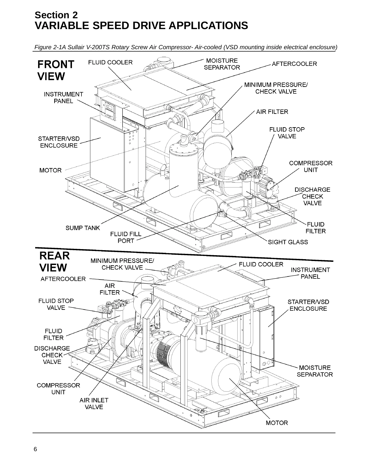
This Sullair V-200TS Operator Manual and Parts List Addendum, document 02250146-047, is the working reference for the Sullair V-200TS two-stage, fluid-lubricated rotary screw air compressor fitted with variable speed drive and the Supervisor Controller. It addresses the 100 HP through 200 HP range in both air-cooled and water-cooled builds, and it covers machines with the VSD mounted inside the electrical enclosure as well as those with an external VSD. Operators, in-house maintenance staff and field service technicians will find the safety requirements, start-up checks, control descriptions and the complete illustrated parts breakdown in one document.
File Details
- Manual type: Operator Manual and Parts List Addendum
- Brand: Sullair
- Model: V-200TS (V200TS) rotary screw air compressor
- Document number: 02250146-047
- Language: English
- File format: PDF
- Page count: 102 pages
- Coverage: 100 HP to 200 HP / 75 KW to 150 KW, 50 Hz and 60 Hz models
- Configurations: Air-cooled and water-cooled, VSD inside the electrical enclosure or external VSD
Chapters Covered
- Section 1 – Safety: general precautions, personal protective equipment, pressure release, fire and explosion, moving parts, hot surfaces and sharp edges, toxic and irritating substances, electrical shock, lifting, entrapment
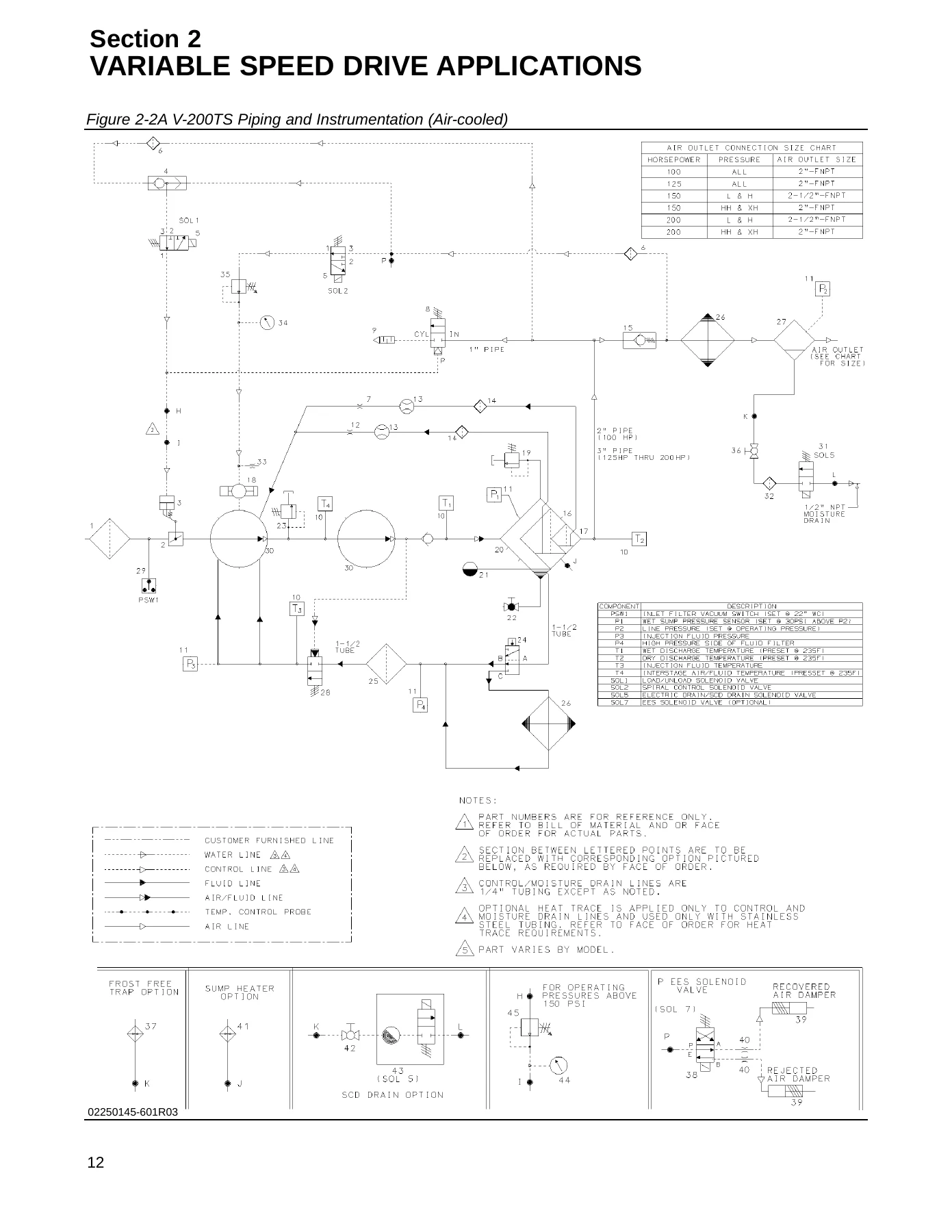
- Section 2 – Description: introduction, description of components, Sullair compressor unit functional description, control system functional description
- Section 3 – Specifications: Sullair V-200TS specifications
- Section 4 – Operation: mounting of compressor, electrical preparation, motor rotation direction check, fan motor rotation check
- Section 5 – Supervisor Controller: panel layout and keypad identification
- Section 6 – Maintenance: spiral valve pressure regulator adjustment
- Section 7 – Illustrations and Parts List: procedure for ordering parts, recommended spare parts list, motor/compressor/frame assemblies, VSD mounting, air inlet assemblies, air piping for air-cooled and water-cooled machines, pneumatic controls, starter assemblies, enclosures, decal group and decal locations, CE and non-CE wiring diagrams
The sections above outline the shape of the book, but the real value sits in the detail underneath them. The description chapter explains how the two-stage compressor unit, the inlet valve and the variable speed drive work together across the start, full load, part load, modulating and unload phases, including how the spiral valve is brought in when motor speed falls toward its minimum setting. That functional picture is what allows a technician to tell a control problem apart from a mechanical one instead of swapping parts. The parts side of the addendum is equally practical: every assembly group is presented as an exploded illustration with a keyed table listing description, part number and quantity, with separate columns for the 100 HP / 75 KW, 125-150 HP / 93-112 KW and 200 HP / 150 KW ratings where the components differ.
Safety Content Built Into the Manual
Section 1 is not a formality. It sets out the pressure release requirements for air hoses over 13 mm inside diameter, the correct sequence for bleeding the sump to zero pressure before opening a filler cap or any line, the lockout and tagout steps to use before repairs, and the rules for lifting the package by bail or sling. There are also specific cautions about not using compressor air for breathing, about antifreeze compound handling for air line anti-icer systems, and about keeping personnel clear of discharge openings. Anyone commissioning or servicing a V-200TS should read that section before touching the machine.
Operation and Commissioning Information
The operation chapter covers the foundation and mounting requirements, including the need to level and secure the frame with foundation bolts and to avoid transmitting piping loads to the compressor at the external connections. It then walks through electrical preparation, checking incoming voltage against the nameplate rating, verifying tightness of connections, and confirming motor rotation by jogging the START and STOP buttons and observing the shaft direction from the end opposite the compressor unit. The same procedure is given for the fan motor, with the caution that cooling air must always flow outward from the compressor. Correct rotation on a rotary screw package is not a detail to guess at, and the manual states plainly how to verify it and how to reverse two leads if it is wrong.
Supervisor Controller and Spiral Valve Maintenance
The Supervisor Controller panel is presented with a labelled illustration identifying the emergency stop, the display panel, the keypads and the Power, On, Auto and Remote buttons, along with the sensor and transducer references P1, P2, T1, T2, dP1 and dP2. The manual points the reader to the separate Supervisor Controller manual for the full operating detail of that device. The maintenance section is short but specific: it explains how to set the spiral valve pressure regulator by slowly reducing demand until the compressor runs at minimum speed, then adjusting the screw on the bottom of the regulator until the downstream gauge reads 38-40 psig, and locking it there. That single adjustment has a direct effect on how cleanly the machine modulates, and the manual treats it as a routine service point rather than a mystery.
Illustrated Parts List and Wiring Diagrams
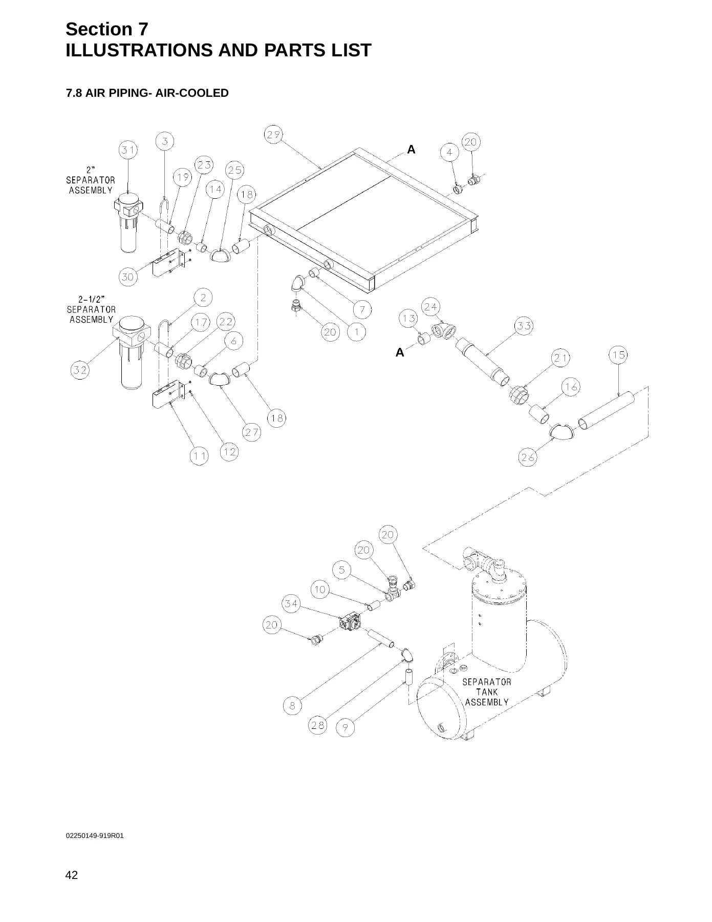
The parts portion of this Sullair V-200TS parts list addendum is where the document earns its keep on a shop floor. Exploded views cover the motor, compressor and frame group for both the in-enclosure VSD and external VSD arrangements, the VSD mounting brackets, the air inlet assemblies for 100-150 HP and 200-250 HP machines, the complete air piping runs for air-cooled units, three separate water-cooled air piping sections, the pneumatic control cluster, the starter assemblies, and the air-cooled and water-cooled enclosures. Each illustration is keyed to a table of part numbers and quantities so a replacement can be identified without guesswork. The decal group and the six decal location drawings show exactly where each warning, fluid, rotation, voltage and branding decal belongs on open and enclosed machines, and the control box decal layout is drawn separately. Two full wiring diagrams close the book, one for non-CE machines and one for CE machines, covering the VSD module, transformer, contactors, relays, RTD probes and pressure transducers.
What You Can Do With This Manual
With this Sullair V-200TS operator manual and parts list addendum on hand you can commission a machine correctly, verify motor and fan rotation before first run, follow the pressure release and lockout sequence safely, read the Supervisor Controller panel without guessing at button functions, set the spiral valve pressure regulator to the specified 38-40 psig, and identify replacement parts from exploded views keyed to part numbers and quantities for your specific horsepower rating. You can trace control and power wiring on CE and non-CE builds, confirm where every safety and fluid decal belongs, and understand the sequence of start, full load, part load, modulating and unload operation so that a fault can be traced to the right system instead of the nearest convenient one. For a 100 HP to 200 HP two-stage variable speed rotary screw package, that combination of operating procedure and illustrated parts data is what keeps the machine running to its rated pressure range and keeps maintenance decisions factual.
IMAGES PREVIEW
Working from the correct procedure and the correct specification matters on a compressor of this size. Incorrect rotation, an unset spiral valve regulator, or a part ordered against the wrong horsepower column all cost time and money, and this document is arranged to prevent each of those outcomes. It is delivered as an instant PDF download, no shipping and no waiting, readable on a laptop, tablet or phone in the plant or printed out page by page for the maintenance binder.

Reviews
There are no reviews yet.