
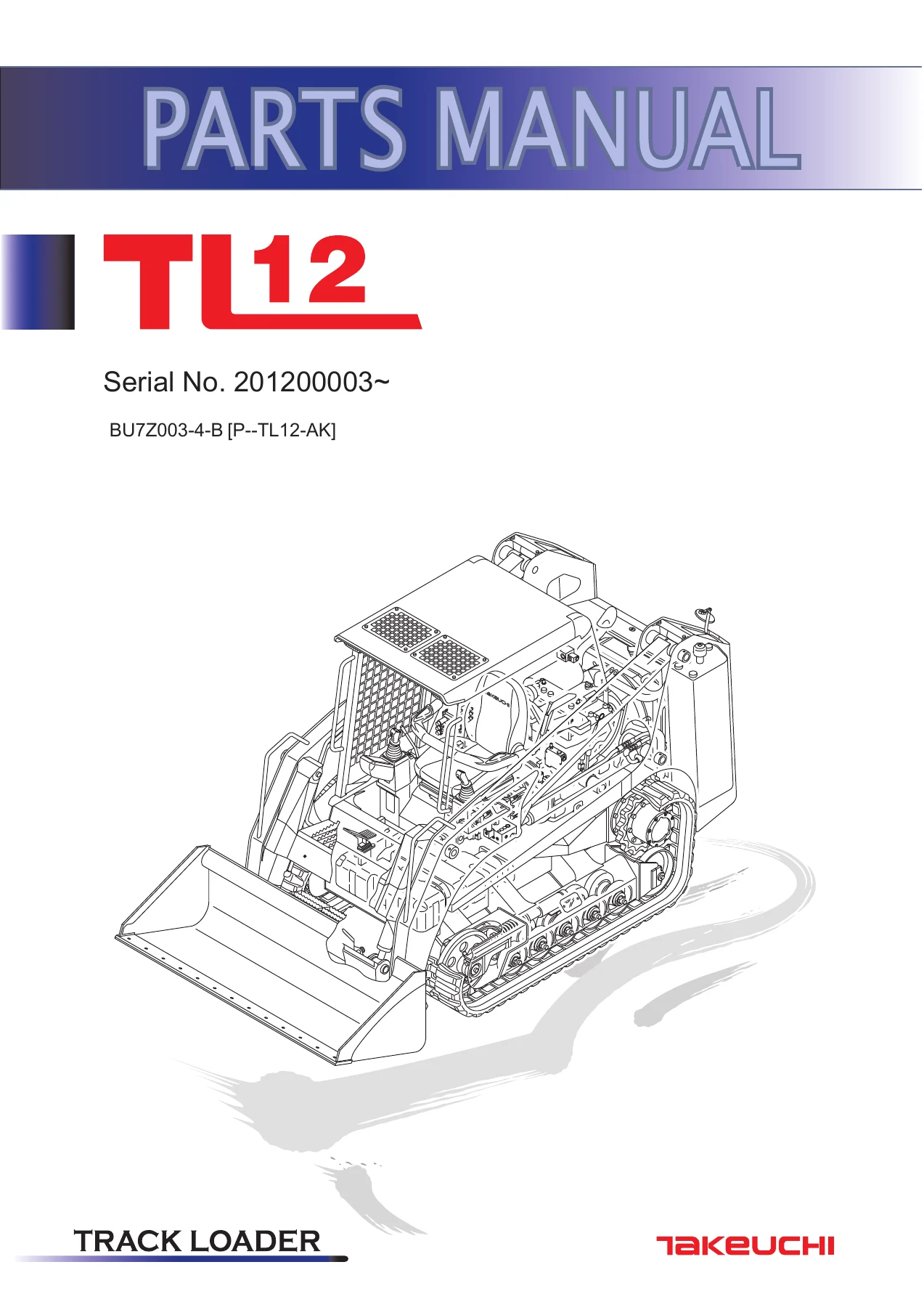
Takeuchi TL12 Track Loader Parts Manual Serial 201200003- BU7Z003-4-B PDF
Original price was: $32.95.$19.95Current price is: $19.95.
Takeuchi TL12 parts catalog for serial 201200003 and up. Exploded views and part numbers for undercarriage, Kubota V3800 engines, hydraulics, cab, hitch, and high-flow options under document BU7Z003-4-B.
Description
Takeuchi TL12 Track Loader Parts Manual Serial 201200003- BU7Z003-4-B PDF
This download is the Takeuchi TL12 parts catalog printed as document BU7Z003-4-B [P-TL12-AK]. The cover identifies the machine as a Takeuchi track loader and opens coverage at serial 201200003~. Every illustrated group in the book is built the same way a parts counter uses it: an exploded drawing, an item callout, a Takeuchi or Kubota part number, a quantity, a unit of measure, remarks, and a serial-number column when a component changed during production.
File Details
- Manual type: Parts manual / parts catalog
- Brand / model: Takeuchi TL12 track loader
- Document number: BU7Z003-4-B [P-TL12-AK]
- Serial coverage: 201200003~
- Language: English (French decal sets are also listed)
- Page count: 677
- File format: PDF
Who This Catalog Is For
The Takeuchi TL12 Track Loader Parts Manual Serial 201200003- BU7Z003-4-B PDF is written for owners, fleet shops, and independent technicians who already know how to pull a roller, swap a pilot valve, or order a DPF core and need the exact piece number before they pick up the phone. It is not a workshop procedure book. What it does give you is the full breakdown of assemblies that wear, leak, or get damaged on a compact track loader: rubber tracks, track rollers A and B, front idlers, grease-type track adjusters, travel motors and sprockets, lift-arm and bucket cylinders, quick-hitch hardware, cab and canopy glass, air-conditioner components, and two complete Kubota V3800 common-rail engine tear-downs.
Because the TL12 was sold with canopy or cab, standard or high-flow hydraulics, mechanical or hydraulic quick hitch, ISO-H pattern add-on piping, CCV heater, polycarbonate door kits, and second-auxiliary lines, the catalog splits those options into separate illustrations instead of burying them in a single “one machine fits all” drawing. Matching the illustration title to the machine in front of you is how you avoid ordering the wrong hose bank or the wrong control-box layout.
Machine Identity, Engines, and Serial Splits
The machine on the title page is the TL12. Engine sections are titled KUBOTA V3800-CR-TIE4B-TLTU1 (HIGH FLOW) and KUBOTA V3800-CR-TIE4B-TLTU2, both marked S/N 201200003-. In the engine-and-accessories lists the same two engines appear as complete assemblies, including a high-flow CCV variant of the TLTU1. Electrical groups are split by machine serial: one set of harness and component pages covers 201200003-201201480 plus 201201493 and 201201494; the later set covers 201201481-201201492 and 201201495 onward. Solenoid-valve blocks also change at 201201271 / 201201272. Several individual lines carry their own breaks, for example a sprocket listing limited to 412000006~412000578 and an engine assembly line limited to 201200177~201200608. Always read the SERIAL NUMBER column on the page you are ordering from.
Undercarriage remarks on roller, idler, and sprocket assemblies note interchange with related Takeuchi compact loaders (TL10, TL12R/V-2, TL140, TL150, TL240, TL250) when the same sub-assembly is used. Those notes are interchange remarks, not a claim that this book is the full parts catalog for those other models. The catalog itself is the TL12 book.
Undercarriage and Travel
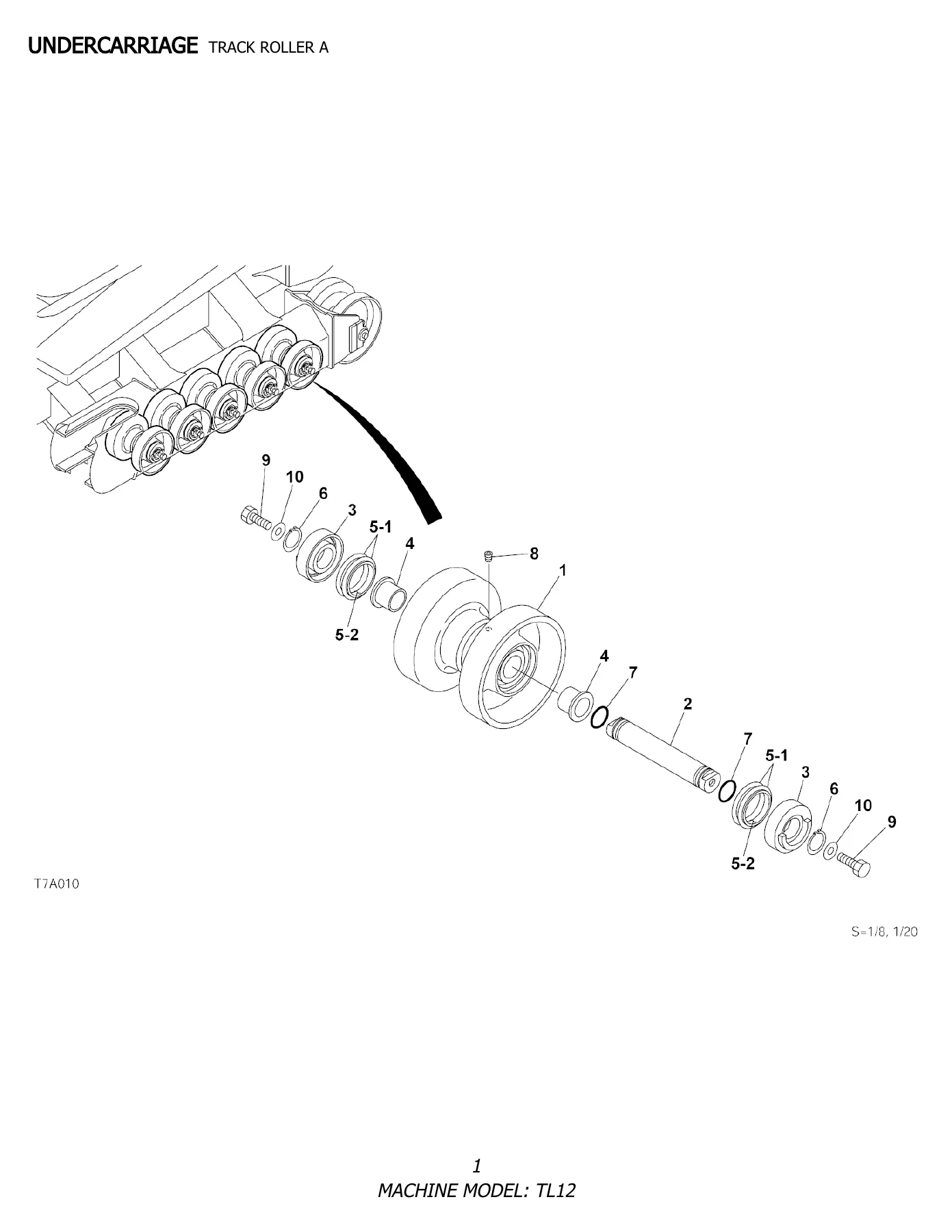
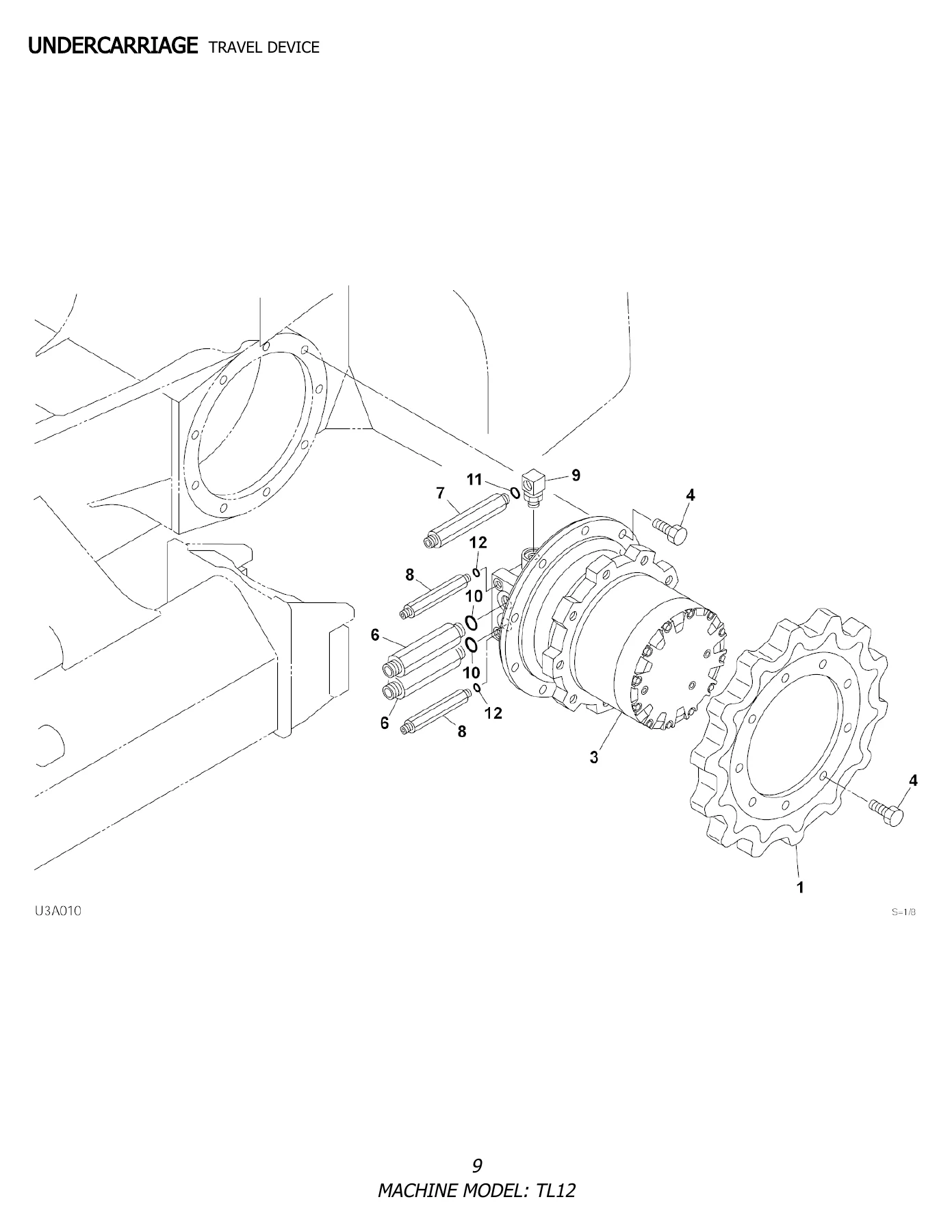
The opening section is the running gear. Track Roller A is a ten-roller group with shaft, covers, bushings, floating seals (sold as a two-piece seal), snap rings, O-rings, a fill plug, and M16 hardware. Track Roller B is the rear pair, using a different shaft and cover set plus bearings 1305000004. The front idler uses bearings 1305000005 and a larger floating seal 1432500800. The track adjuster is a left-hand / right-hand spring assembly with yoke, rod, grease cylinder, piston, check valve, oil seal, O-ring, and back-up ring. Travel device pages show sprocket 0881160110, travel motor 1903129500, mounting bolts, and the adaptor / elbow / O-ring stack that connects the motor to the machine plumbing. Crawler belts are listed as rubber track 1914099320 (aggressive bar) plus aftermarket S-wave and C-lug options coded ATTL150SW and ATTL150TAK for TL12 / TL150 / TL250.
Frame, Controls, Cab, and Operator Station
Main-frame pages cover frame covers, arm stoppers with 0.5 mm / 1.0 mm / 3.2 mm shims, and lifting lugs. Operation lever and stand pages break out U.S. right-hand and left-hand bracket assemblies, pilot valve 1901754000 (R.H.) and 1901753900 (L.H.), five-switch and slide-switch handle assemblies, boots, receptacles, and the sponge / seal kits sold by the meter. Separate piping chapters exist for the standard operation-lever circuit and for the ISO-H pattern add-on type.
Cover and cab chapters run from rear door and engine hood through floor frame, PVC and related seat assemblies, three-point seat belt, seat switch, safety bar, canopy mount and three canopy illustrations, cab mount, multi-page cab breakdowns, front door (including polycarbonate), cab kits, door kits, and rear mirror. Air conditioner is split across compressor, condenser, air-conditioner unit, and two further pages of related hardware. Decal chapters give English and French sets for canopy and cab plus a high-flow decal page, so replacement safety and brand markings can be ordered by language and cab style.
Hydraulics, Tanks, and Attachment Circuit
Valve-and-accessories groups cover the standard and high-flow control-valve installations, manual parking brake, machine piping, ride control, pump drive, high-flow gear-pump drive, hydraulic tank, and two-part fuel tank and fuel piping. Attachment pages list the lift arm, mechanical quick hitch, hydraulic quick hitch (including the 3/4 coupler version), and multiple arm-piping variants: standard, with coupler, high flow, high flow with 3/4 coupler, and high flow with coupler on the hydraulic-hitch machine. Second-auxiliary line pages cover both the main-aux and except-main-aux layouts.
The Hydraulic Device section then explodes the components those hoses feed: control valve and high-flow control valve, block assemblies No. 1 / No. 2 / No. 3, pilot valves, handles, sub valve, solenoid valves by serial break, electrical proportion valve, ISO-H selector and shuttle valves, lift-arm cylinder, bucket cylinder, quick-hitch cylinder, travel motor in reduction / motor / valve sections, hydraulic pump in five figures, two-block gear pump, and high-flow gear pump. Those pages are where seal kits, adaptors, and internal valve pieces live when a complete assembly is no longer the economical repair.
Kubota V3800 Engine Breakdown
Two parallel engine catalogs occupy the second half of the Takeuchi TL12 Track Loader Parts Manual Serial 201200003- BU7Z003-4-B PDF. TLTU1 (high flow) begins at the catalog page marked Fig.1 Crank Case and runs through oil pan, dipstick, cylinder head, valves, rocker shaft, head cover, gear case, piston and crankshaft, camshaft and idle gear, bearing-case cover, flywheel, supply pump, fuel filters and pipes, separator, injection pipe, common rail, 12V 80A alternator and component parts, 12V 3 kW starter and component parts, switches and sensors, injector harness, water flange and thermostat, water pump, reserve tank, fan and pulley, inlet manifold, air-cleaner flange and throttle valve, exhaust manifold, EGR valve and cooler, turbocharger, diesel particulate filter muffler and component parts, DPF cleaning program and order form dated REV 021418, DPF muffler sensors, differential-pressure pipe, breather and separator pipes (including the CCV-heater version), oil separator, turbo oil pipe, oil cooler, oil filter, hydraulic-pump base, ECU, accessories, optional piston kit, and optional Diagmaster. TLTU2 repeats the same figure structure for the second engine specification. That dual listing is why a shop can identify whether a failed fuel filter, common-rail assembly, or DPF sensor belongs to the high-flow TLTU1 or the TLTU2 build.
Kits and Quick-Reference Lists
Closing sections collect block heaters, buckets-blades-attachments, a Tier 4 operators quick-reference card, recommended stock list for the TL12, Takeuchi fleet-management component guide, fuse detail 11-18-16, TL12-TL150-TL250 undercarriage track kits, winter kit, and Appendix A / Appendix B page and parts indexes. Those lists are the fastest way to pull filters, seal kits, and common wear items without paging through every exploded view.
Chapters Covered
- Undercarriage — Track Roller A, Track Roller B, Front Idler, Track Adjuster, Travel Device, Crawler Belt
- Main Frame & Control Lever — Frame 1 and 2, Arm Stopper, Hook, Operation Lever & Stand, Piping; Operation Lever, ISO-H pattern add-on piping 1 and 2
- Engine & Electrical System — Engine & Accessories 1/4 through 4/4 (including CCV-heater variants), Drain Plug, Control Box R.H. and L.H. (including hydraulic quick-hitch L.H.), Engine Control, Foot Accelerator, Electrical 1/2 and 2/2 by serial group, Electrical cab and canopy, GPS Device, Battery, Rear Lamp, Maintenance Light Socket, Window Washer, Radio
- Hydraulic Piping & Tank — Valve & Accessories 1/3 through 3/3 (standard and high flow), Manual Parking Brake, Piping 1 and 2, Ride Control, Pump Drive, Gear Pump Drive (high flow), Hydraulic Tank, Fuel Tank & Fuel Piping 1/2 and 2/2
- Cover & Cab — Covers 1/3 through 3/3, Floor Frame, Seat 1/2 and 2/2, Seat Belt (three point), Seat Switch, Safety Bar, Canopy Mount and Canopy 1-3, Cab Mount, Cab 1/2 and 2/2 (front door and polycarbonate), Cab Kit, Door Kit, Rear Mirror, Air Conditioner 1/5 through 5/5
- Attachment — Arm, Quick Hitch, Quick Hitch hydraulic and 3/4-coupler variants, Piping; Arm in standard, coupler, high-flow, and hydraulic-hitch combinations, 2nd Auxiliary Line
- Decal & Tool — Decal canopy and cab (Takeuchi U.S. and French), Decal (high flow), Tool & Accessories, Painted Color, Service Tool
- Hydraulic Device — Control Valve, high-flow Control Valve, Block Assy No. 1-3, Pilot Valves R.H./L.H., Handles, Sub Valve, Solenoid Valves, Electrical Proportion Valve, ISO-H Selector and Shuttle Valves, Lift Arm / Bucket / Quick Hitch Cylinders, Travel Motor 1/3-3/3, Hydraulic Pump 1/5-5/5, Gear Pump
- Engine Kubota V3800-CR-TIE4B-TLTU1 (High Flow) — Fig.1 through Fig.53 including DPF cleaning program and order form
- Engine Kubota V3800-CR-TIE4B-TLTU2 — matching figure set from crank case through Diagmaster option
- Kits, Attachments & Quick Reference — block heaters, buckets and blades, recommended stock, fleet-management guide, fuse detail, track kits, winter kit, Appendix A Pages Index, Appendix B Parts Index
Taken together, those chapters give a technician a single lookup path from a worn track roller or a leaking arm hose to a printed part number, quantity, and serial applicability. The engine figures extend that same lookup into Kubota-numbered internals, emissions hardware, and the DPF core-return paperwork bound into the catalog.
How to Use the Illustrations and Indexes
Find the system first in the contents, open the matching exploded view, read the item balloon on the drawing, then drop to the table for Part No., Name, Qty, and Remarks. Aftermarket lines are flagged in the name field (for example ROLLER SUB ASSY, track (AFTERMARKET)(CHECK MODELS)). Non-service pieces such as floating-seal O-rings are marked NOT SERVICE so you order the complete seal, not a hidden inner ring. Metered items such as trim, sponge, and hose protector are sold by the meter. When a block assembly is marked no longer available, the detail pages still list the serviceable internals that remain orderable.
Appendix A and Appendix B at the back of the Takeuchi TL12 Track Loader Parts Manual Serial 201200003- BU7Z003-4-B PDF are the page index and parts index. Use them when you already have a number from a tag or an invoice and need the illustration that shows how that number sits in the assembly.
Order the Correct TL12 Part the First Time
With this catalog you can identify track rollers, idlers, adjuster cylinders, travel motors, sprockets, and rubber tracks; match cab versus canopy glass, doors, seats, and decals; separate standard, high-flow, coupler, and second-aux hose banks; pull control-valve, pilot-valve, cylinder, and pump internals; and order Kubota V3800-CR-TIE4B-TLTU1 or TLTU2 engine parts including DPF-related sensors and the cleaning-order form. Correct part numbers and serial breaks matter on a loader that changed electrical harnesses, solenoid blocks, and engine assemblies during the 201200003-plus run. Ordering from the wrong illustration is how shops receive a canopy decal set for a cab machine or a TLTU1 high-flow engine piece for a TLTU2. Instant PDF delivery after payment means you can open the file on a shop computer, tablet, or phone and print only the page you need at the bench. No shipping wait and no need to keep a paper binder in the service truck.
Reviews
There are no reviews yet.