
TCM FB-8 Series Electric Forklift Service Manual – FB10-8 to FB35-8 Repair Guide PDF
Original price was: $59.95.$39.95Current price is: $39.95.
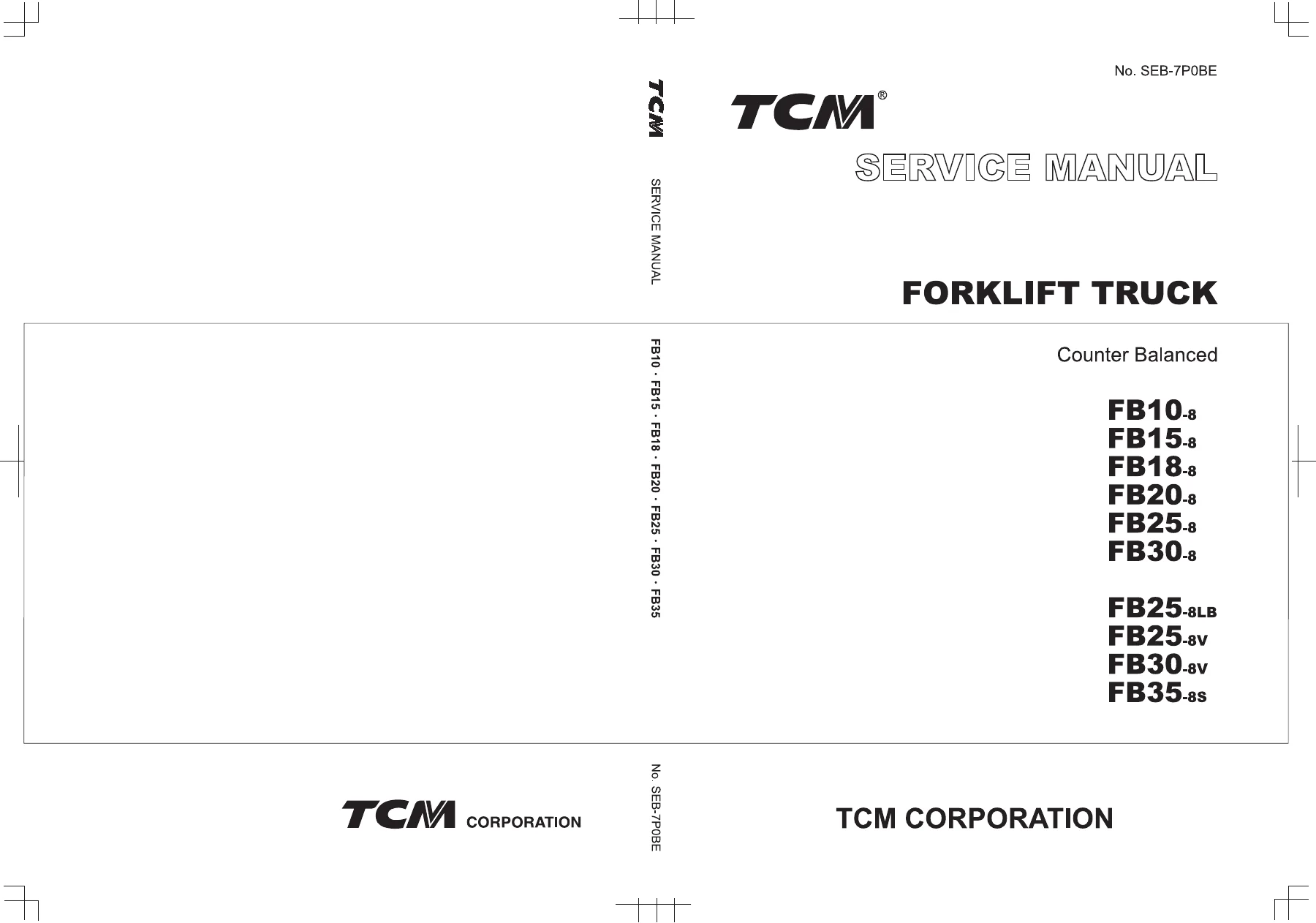
Complete TCM FB-8 Series service manual for FB10-8, FB15-8, FB18-8, FB20-8, FB25-8, FB30-8 and FB35-8 counter balanced electric forklifts. Covers motors, inverter control system, drive axle, brakes, Orbitrol and EPS steering, hydraulics, mast and full wiring with torque specs, exploded views and self-diagnosis troubleshooting.
Description
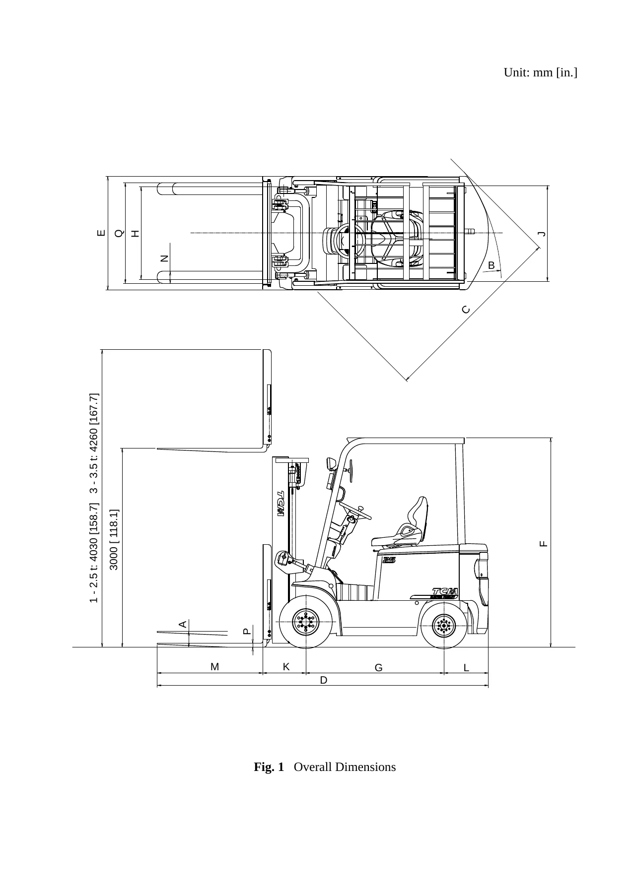
This TCM FB-8 Series electric forklift service manual is the full workshop reference for the counter balanced battery-powered trucks in the FB-8 line, taking in FB10-8, FB15-8, FB18-8, FB20-8, FB25-8, FB30-8 and FB35-8, along with the FB25-8LB, FB25-8V and FB30-8V variants. Published by TCM Corporation under document number SEB-7P0BE and revised December 2012, it takes a technician from the drive, pump and power-steering motors through the inverter-based control system, the drive axle, duo-servo wheel brakes, both Orbitrol and EPS steering layouts, the hydraulic circuit, the two-stage telescopic mast, and the complete electric wiring — backed up by exploded illustrations, torque values, adjustment clearances, wear limits and a structured error-code troubleshooting guide.
File Details
- Manual type: Service Manual
- Brand / publisher: TCM Corporation
- Models covered: FB10-8, FB15-8, FB18-8, FB20-8, FB25-8, FB30-8, FB25-8LB, FB25-8V, FB30-8V, FB35-8S
- Document number: SEB-7P0BE
- Edition / date: Issued July 2012, revised December 2012
- Language: English
- Page count: Approximately 259 pages
- File format: PDF
Chapters Covered
- Battery and Charger (Option)
- Motors
- Control System
- Drive Unit and Drive Axle
- Brake System
- Steering System (Orbitrol type)
- Steering System (EPS type)
- Hydraulic System
- Load Handling System
- Electric System
- Control Circuits
- Electrical Parts and Procedures for Checking
- Troubleshooting Guide
- Parameter Setting
- Description of the Functions
- Electric Wiring
Battery and Charger (Option)
Describes the 48 V and 72 V traction battery packs, electrolyte specific gravity checks, temperature correction, equalizing and super-equalizing charge routines, and the on-board three-phase AC semiconductor charger. Transformer tap selection, diode and fuse layout, LCD operation panel, charging procedures and charge-timer fault checks are all covered, so a technician can diagnose both the battery and the charger on the truck.
Motors
Detailed coverage of the self-ventilated three-phase induction drive and pump motors across the 1.0 t to 3.5 t classes, with rated output, voltage and current data, tightening torques for the U, V and W phase terminals, rotation sensor and thermo-sensor checks, plus bearing replacement intervals and installation procedures for the FB-8 electric drivetrains.
Control System
Explains the inverter unit architecture — CPU board, FET modules and capacitor boards — that converts DC to three-phase AC for the drive and pump motors, plus the accelerator pedal and potentiometer. Terminal locations, connector pin numbering, capacitor and FET resistance tests, and heat-dissipating sheet application are all spelled out for the FB-8 controller assembly.
Drive Unit and Drive Axle
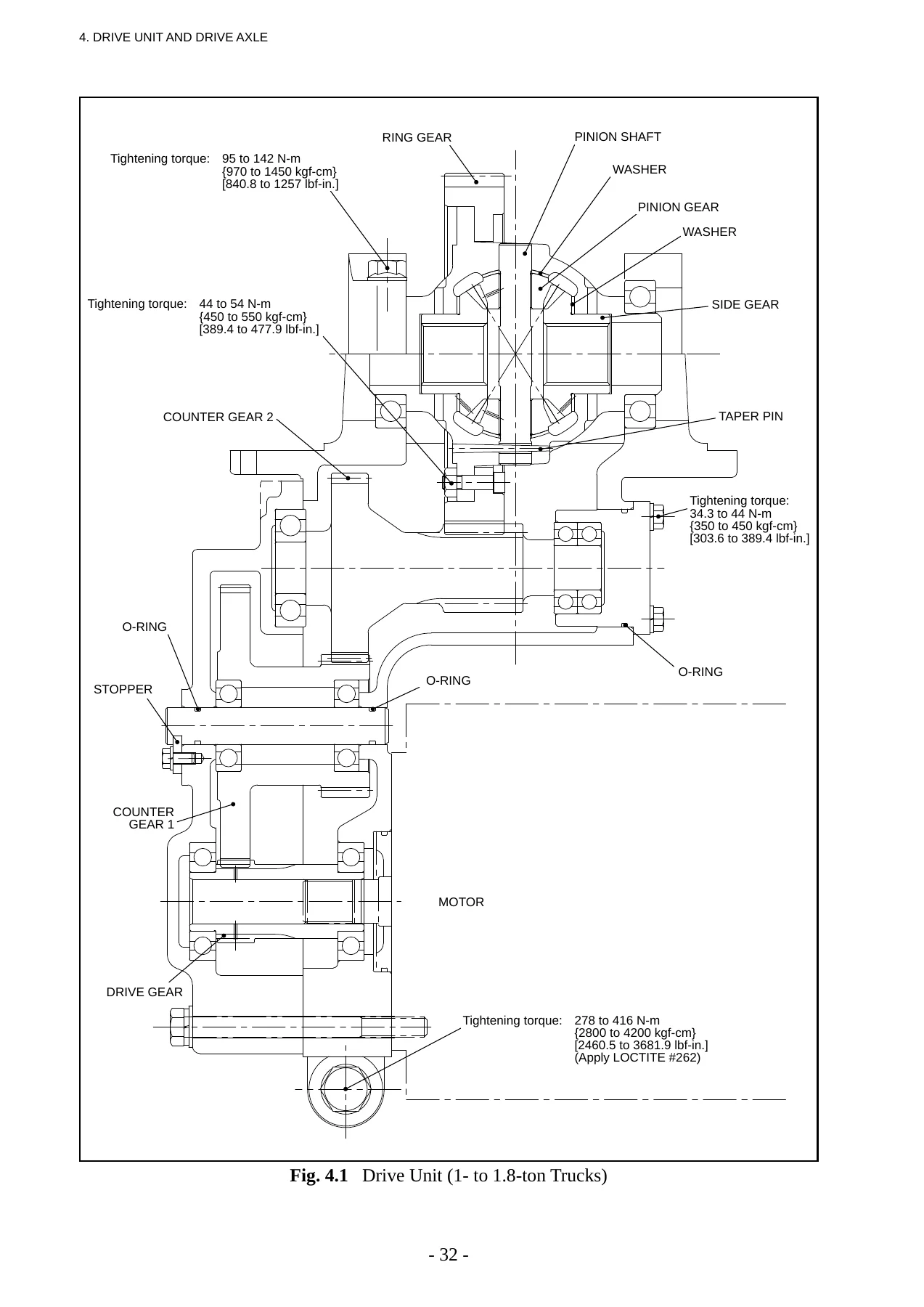
Covers the three-stage reduction drive unit with its counter gears, differential, ring gear and reamer bolt, and the full floating drive axle with tapered roller bearings, adjustment nut, lock nut and hub installation. Starting torque, hub nut tightening values and grease fill quantities are given, along with three separate exploded views for 1.0–1.8 t, 2.0–2.5 t and 3.0–3.5 t trucks.
Brake System
Full teardown and rebuild of the front two-wheel duo-servo hydraulic brake — brake pedal, master cylinder, wheel cylinder, brake shoes, drum and automatic clearance adjuster — plus the built-in mechanical parking brake and lever pull-force adjustment. Lining thickness, drum inner diameter limits, spring free length and piston-to-cylinder clearance values are all listed, along with a brake-specific troubleshooting table.
Steering System (Orbitrol type and EPS type)
Two complete steering chapters. The Orbitrol chapter covers the steering axle, knuckle and king pin, steering wheel assembly, orbitrol valve operation in neutral, left and right turns, power cylinder rebuild and the flow divider valve. The EPS chapter covers the steering gearbox, electric actuator with ball nut and screw, rear axle, knuckle preload adjustment, and actuator boot, ball joint and motor replacement procedures.
Hydraulic System
Everything hydraulic on the FB-8: main gear pump rebuild (with gasket and side-plate orientation diagrams), control valve plunger sections, relief valve pressure setting, lift and tilt cylinders, cut-off valve, flow regulator valve, hydraulic oil tank and filters. Relief pressures, cylinder bores, rod diameters and strokes are given for each truck class, plus a full pump disassembly and trial-run procedure.
Load Handling System
Covers the VM-7P1, VM-7P4, VM-7P5, VM-7P7 and VM-7P9 two-stage telescopic masts with free lift, including outer and inner channel dimensions, carriage, end rollers and side rollers. It gives the shim adjustment for carriage height, lift cylinder rod shimming, chain tension adjustment and the full roller replacement procedures at both carriage and mast side.
Electric System
Describes the relay unit and the truck lighting: head lights, front combination lights with turn signal and side marker, rear combination lights with brake, tail, turn, back-up and beacon options, plus the integrated turn signal and light switch. Bulb replacement and relay unit terminal layout are included.
Control Circuits, Electrical Parts and Wiring
The final block opens with control circuit diagrams for the drive, load handling and power steering systems, then walks through every electrical component — controller assembly, inverter units, EPS motor controller, MC and CM contactors, fuses, fast charge resistance, accelerator pedal, motor rotation sensors, lift and steering potentiometers, LCD panel, switch panels, charge rectification diode, thermo-sensors and F/R switch. Wire harness diagrams and full circuit diagrams close out the manual for 1.0–2.5 t and 3.0–3.5 t trucks.
Troubleshooting, Error Codes and Parameter Setting
A dedicated troubleshooting guide lists every controller error code with its LED code, condition, reset behaviour and step-by-step repair path, alongside a problem-based diagnostics section for symptoms such as ‘truck won’t travel’, ‘hard steering’ or ‘LCD panel blank’. The manual also documents the parameter setup screens, keypad operation, factory settings, level tables and password configuration — useful when tuning acceleration, travel speed limits, lift speed and regeneration levels on the FB-8.
Standard Bolt Tightening Torques and Maintenance Standards
Reference tables give the maintenance standard list for the whole truck — motor brush wear, hub nut torques, brake drum limits, chain stretch, lift cylinder natural drop — plus the standard bolt tightening torque charts for 4.6, 4.8, 6.8, 8.8 and 10.9 strength classes in both metric fine and coarse thread, including LOCTITE and dry values. Lubrication guidance for lift chains, mast and steering system rounds off the reference material.
Put the TCM FB-8 Series Service Manual to Work
Whether you are servicing a single FB15-8 or running a mixed fleet of FB-8 counter balanced electric forklifts, this TCM service manual gives you the procedures, torque values and diagnostic logic to do the job correctly the first time. It supports drive and pump motor rebuilds, controller and inverter fault-finding, brake overhaul, hydraulic pump and cylinder repair, mast roller replacement, and full electric wiring diagnosis — all with the exact wear limits and adjustment figures TCM specifies, instead of guesswork.
Correct procedures and correct specifications matter on battery-powered forklifts. An over-shimmed carriage, a wrongly torqued hub nut or a mis-set relief valve can shorten component life, compromise braking, or leave the truck in a fault state that no amount of parts swapping will fix. This manual gives you the factory reference values and the systematic error-code path so you can diagnose instead of guess.
IMAGES PREVIEW
Delivered as an instant PDF download after checkout, the manual opens on any laptop, tablet or smartphone and every page is printable, so you can keep the exploded views and torque charts right beside the machine while you work. No shipping, no waiting — download the TCM FB-8 Series electric forklift service manual today and put the full workshop reference in your hands.
Reviews
There are no reviews yet.