Tektronix TDS520A TDS524A TDS540A TDS544A Oscilloscope Service Manual PDF
Original price was: $85.00.$16.95Current price is: $16.95.
Official Tektronix TDS520A/524A/540A/544A digitizing oscilloscope service manual for professional technicians. This comprehensive 298-page PDF covers complete maintenance, troubleshooting, circuit descriptions, performance verification, and adjustment procedures for Tektronix 500 MHz bandwidth digital oscilloscopes. Includes detailed theory of operation, self-diagnostic routines, module-level repair procedures, and calibration instructions. Essential technical documentation for servicing these high-performance 2-channel and 4-channel scopes.
Description
Tektronix TDS520A TDS524A TDS540A TDS544A Oscilloscope Service Manual – PDF DOWNLOAD
DESCRIPTION
Tektronix TDS520A/524A/540A/544A Digitizing Oscilloscope Service Manual – Complete Professional Reference
This is the official factory service manual for the Tektronix TDS 520A, 524A, 540A, and 544A series digitizing oscilloscopes. Published by Tektronix, Inc. in April 1999 (Part Number 070-8713-03), this professional-grade technical documentation is essential for oscilloscope service technicians, electronics repair specialists, calibration laboratories, and engineering teams who maintain these high-performance test instruments.
📋 FILE DETAILS
- Manual Name: TDS 520A, 524A, 540A, & 544A Service Manual
- Models Covered:
- Tektronix TDS 520A (2-channel, 500 MHz)
- Tektronix TDS 524A (2-channel, 500 MHz, color display)
- Tektronix TDS 540A (4-channel, 500 MHz)
- Tektronix TDS 544A (4-channel, 500 MHz, color display)
- Publication Date: April 1999
- Part Number: 070-8713-03
- Total Pages: 298 pages
- File Format: PDF
- PDF Quality: High-quality official manual
- Language: English
🔧 COMPREHENSIVE COVERAGE INCLUDES:
Chapter 1: Specifications (Complete Technical Reference)
TDS 520A & 524A (2-Channel Models):
- Bandwidth: DC to 500 MHz (full bandwidth)
- Selectable bandwidth limiting: 20 MHz, 100 MHz, FULL (500 MHz)
- Channels: 2 full-featured (CH1, CH2) + 2 limited auxiliary (AUX1, AUX2)
- Digitizers: 2 identical, 8-bit resolution
- Sample Rate: Up to 1 GS/s (Giga-samples per second)
- Input Impedance: 50Ω ±1% (DC-50Ω coupled)
- Vertical Sensitivity:
- CH1/CH2: 1 mV/div to 10 V/div
- AUX1/AUX2: 100 mV/div, 1 V/div, 10 V/div
- Display: TDS 520A (monochrome), TDS 524A (color)
TDS 540A & 544A (4-Channel Models):
- Bandwidth: DC to 500 MHz (full bandwidth)
- Selectable bandwidth limiting: 20 MHz, 100 MHz, FULL (500 MHz)
- Channels: 4 full-featured, all identical (CH1-CH4)
- Digitizers: 4 identical, 8-bit resolution
- Sample Rate: Up to 1 GS/s per channel
- Input Impedance: 50Ω ±1% (DC-50Ω coupled)
- Vertical Sensitivity: 1 mV/div to 10 V/div (all channels)
- Display: TDS 540A (monochrome), TDS 544A (color)
Common Specifications:
- Bandwidth Response:
- 5-10 V/div: DC – 500 MHz
- 2-4.98 mV/div: DC – 350 MHz
- 1-1.99 mV/div: DC – 250 MHz
- VSWR: ≤1.3:1 from DC to 500 MHz
- Maximum Input Voltage: ±400 V (DC + peak AC, DC-1MΩ)
- Input Coupling: AC, DC, GND (50Ω and 1MΩ)
- Trigger System: Main and Delayed
- Advanced Trigger Modes: Edge, Glitch, Pulse Width, Video (Option 05)
- Acquisition Modes: Sample, Peak Detect, Average, Envelope
- Record Length: Variable
- Display: CRT-based, high-resolution
User Interface:
- Front Panel Controls
- Multipurpose Knobs
- Menu System
- Status Display
- On-screen Measurements
- Cursor Measurements
- Automatic Measurements
Signal Acquisition System:
- Horizontal System
- Trigger System
- Acquisition Control
- Real-time and Equivalent-time Sampling
- Interpolation Algorithms
Storage and I/O:
- Waveform Storage
- Setup Storage
- GPIB Interface (IEEE-488)
- RS-232 Interface
- Floppy Disk Drive (standard on 524A/544A, Option 1F on 520A/540A)
- File System
Chapter 2: Operating Information
Using This Manual:
- Before Servicing guidelines
- Strategy for Servicing
- Manual Structure overview
- Manual Conventions and symbols
- Diagrams and schematics interpretation
- Safety precautions
Tektronix Service:
- Warranty Service options
- Service repair locations
- Self-Service options
- Product Support Resources
General Information:
- Power Supply Requirements:
- Operating voltage ranges
- Power consumption specifications
- Memory backup power
- Operating Environment:
- Temperature: Operating and storage ranges
- Humidity specifications
- Altitude considerations
- Ventilation requirements
- Applying and Interrupting Power:
- Power-on sequence
- Power-off procedures
- Emergency power interruption
- Repackaging Instructions for shipping
- Installed Options identification and verification
General Operating Instructions:
- Screen Layout and display elements
- Basic Procedures:
- How to Power On
- How to Use Help system
- How to Use Status Menu
- How to Set Functions
- How to Set Complex Functions
- Front panel control reference
- Menu navigation
Chapter 3: Theory of Operation (Circuit Description)
Logic Conventions:
- Signal naming conventions
- Logic level definitions
- Block diagram symbols
Module Overview: Complete circuit descriptions for all major subsystems:
- Acquisition System architecture
- Digitizer circuits
- Analog front-end design
- Timebase generation
- Trigger circuitry
- Microprocessor systems
- Memory architecture
- Display generation
- Power supply design
- Interface circuits
- Control logic
Detailed Block Diagrams:
- System-level architecture
- Signal path analysis
- Timing relationships
- Control sequences
Chapter 4: Performance Verification
Brief Procedures:
- Quick verification tests
- Go/No-Go testing
General Instructions:
- Conventions for performance testing
- Test equipment setup
- Environmental considerations
Self Tests:
- Power-On Self Test (POST)
- Built-in diagnostic routines
- Internal Adjustment, Self-Compensation, and Diagnostics
- Error code interpretation
- Diagnostic menu access
Functional Tests:
- Verify All Input Channels
- Verify the Time Base
- Verify Main and Delayed Trigger Systems
- Verify the File System (Optional on TDS 520A/540A)
- Display functionality
- Control response
- Interface operation
Performance Tests (Comprehensive):
- Prerequisites and test equipment required
- Equipment Required list with specifications
- Test Record documentation
- Signal Acquisition System Checks:
- Check Accuracy of Offset (Zero Setting)
- Check DC Gain and Voltage Measurement Accuracy
- Check Analog Bandwidth
- Check Delay Between Channels
- Time Base System Checks:
- Check Accuracy for Long-Term Sample Rate
- Delay Time measurements
- Delta Time Measurements accuracy
- Trigger System Checks:
- Check Accuracy (Time) for Pulse-Glitch or Pulse-Width Triggering
- Check Accuracy, Trigger-level or Threshold, DC Coupled
- Sensitivity, Edge Trigger, DC Coupled
- High-frequency trigger sensitivity
- Output Signal Checks:
- Check Outputs (COMP OUT and Main/Delayed Trigger)
- Check Probe Compensator Outputs
- Option 05 Video Trigger Checks:
- Check Video Trigger operation
- NTSC and PAL compatibility
- Field and Line triggering
Chapter 5: Adjustment Procedures
Calibration and Adjustment:
- When to perform adjustments
- Required test equipment
- Environmental requirements
- Warm-up procedures
Adjustment Procedures:
- Internal calibration routines
- Offset adjustments
- Gain calibrations
- Timebase calibration
- Trigger level adjustments
- Display adjustments
- Probe compensator calibration
Chapter 6: Troubleshooting and Repair
Troubleshooting Strategy:
- Symptom-based diagnosis
- Divide-and-conquer approach
- Module-level fault isolation
- Component-level repair
Diagnostic Tools:
- Self-diagnostic routines
- Test points and signals
- Signal tracing techniques
- Built-in diagnostics interpretation
Module Removal and Replacement:
- Safety precautions
- ESD (Electrostatic Discharge) protection
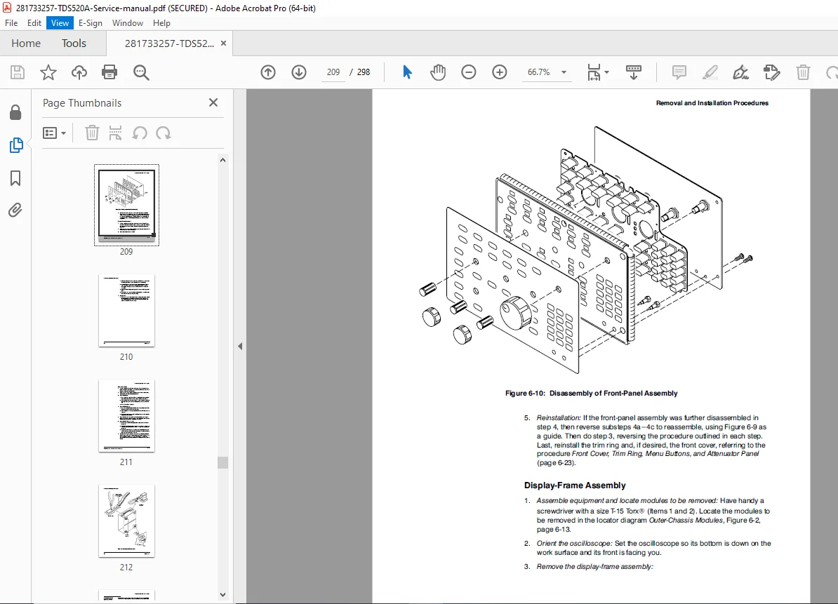
- Disassembly procedures
- Module identification
- Connector locations
- Cable routing
- Reassembly procedures
Common Problems:
- No display
- Incorrect triggering
- Amplitude errors
- Timebase errors
- Interface failures
- Power supply problems
Chapter 7: Replaceable Parts
Parts Lists:
- Complete parts catalog
- Part numbers
- Component locations
- Assembly drawings
- Exploded views
- Module identification
Chapter 8: Schematics and Diagrams
Complete Schematic Set:
- System block diagrams
- Detailed circuit schematics
- PCB layouts
- Signal flow diagrams
- Timing diagrams
- Connector pinouts
- Cable assemblies
- Mechanical drawings
🎯 COVERED MODELS & OPTIONS:
Base Models: ✅ TDS 520A – 2-channel, 500 MHz, monochrome display
✅ TDS 524A – 2-channel, 500 MHz, color display, standard floppy
✅ TDS 540A – 4-channel, 500 MHz, monochrome display
✅ TDS 544A – 4-channel, 500 MHz, color display, standard floppy
Available Options: ✅ Option 05 – Advanced Video Trigger (NTSC/PAL)
✅ Option 13 – Color Display Upgrade (520A/540A)
✅ Option 1F – Internal Floppy Disk Drive (520A/540A)
✅ Various interface and connectivity options
💡 IDEAL FOR:
✅ Authorized Tektronix service centers
✅ Independent test equipment repair specialists
✅ Electronics calibration laboratories
✅ University and research lab technical staff
✅ Military and aerospace equipment maintenance
✅ Broadcast engineering facilities
✅ Telecommunications service departments
✅ Medical equipment service technicians
✅ Industrial electronics repair shops
✅ Anyone servicing high-performance oscilloscopes
🌟 KEY BENEFITS:
- Four Models in One Manual: Complete coverage of entire TDS 5xx series
- Professional-Grade Instrument Service: Factory procedures for precision test equipment
- Save on Calibration Costs: Perform in-house calibrations and adjustments
- Minimize Equipment Downtime: Quick diagnostic procedures reduce repair time
- Preserve Instrument Accuracy: Factory-approved calibration procedures
- Complete Technical Reference: From basic operation to component-level repair
- High-Frequency Expertise: Service procedures for 500 MHz bandwidth instruments
- Self-Diagnostic Mastery: Understand and use built-in diagnostic routines
- Module-Level Repair: Efficient troubleshooting to the replaceable module
- Specifications Verification: Ensure instruments meet published specifications
📊 TECHNICAL HIGHLIGHTS:
Performance Characteristics:
- Bandwidth: DC to 500 MHz (industry-leading for the era)
- Sample Rate: 1 GS/s (Giga-samples per second)
- Resolution: 8-bit vertical digitization
- Input Impedance: 50Ω (precision-matched for high-frequency work)
- Time Base Accuracy: High-precision timebase system
- Trigger Sensitivity: Excellent trigger performance at 500 MHz
- Multiple Acquisition Modes: Sample, Peak Detect, Average, Envelope
- Advanced Triggering: Edge, Glitch, Pulse Width, Video (optional)
Professional Features:
- IEEE-488 (GPIB) interface
- RS-232 communication
- Waveform and setup storage
- Automatic measurements
- Cursor measurements
- Math functions
- Reference waveforms
- Color display options (524A/544A)
⚙️ ADVANCED SERVICE CONTENT:
- Complete Theory of Operation: Understand circuit design and operation
- Module-Level Block Diagrams: System architecture documentation
- Signal Path Analysis: Trace signals through entire system
- Timing Diagrams: Critical timing relationships
- Test Point Locations: Strategic measurement points
- Voltage Specifications: Normal operating voltages
- Adjustment Procedures: Factory calibration methods
- Performance Verification: Detailed test procedures with acceptance criteria
- Troubleshooting Flowcharts: Systematic fault isolation
- Component-Level Schematics: Detailed circuit diagrams
- PCB Layouts: Component placement and identification
- Connector Pinouts: All interface connections documented
📥 DOWNLOAD INFORMATION:
- Instant Download: Immediate access after purchase
- Format: PDF (optimized for digital viewing)
- Compatibility: Works on PC, Mac, tablet, smartphone
- Searchable: Full-text search for quick reference
- Printable: Print entire manual or specific sections
- Bookmarked: Navigate easily to any chapter or section
- High Quality: Clear schematics, diagrams, and illustrations
⚠️ IMPORTANT NOTES:
- This is a professional service manual for qualified technicians
- Contains high-voltage safety warnings (CRT display)
- Requires advanced knowledge of oscilloscope operation and electronics
- Official Tektronix documentation
- Essential for maintaining published specifications
- ESD-sensitive components require proper handling
- Some procedures require specialized test equipment
🔧 REQUIRED TEST EQUIPMENT (For Full Performance Verification):
- Precision DC Voltage Source
- Variable Frequency Function Generator (to 500 MHz)
- Leveled Sine Wave Generator (250-500 MHz)
- Tektronix SG 504 Leveling Head (recommended)
- Precision Frequency Counter
- 50Ω Terminations and Precision Attenuators
- High-frequency coaxial cables
- Oscilloscope Probes (10:1, calibrated)
- Digital Multimeter
- Video Signal Generator (for Option 05 testing)
🌟 WHY CHOOSE THIS MANUAL?
This is the authentic Tektronix factory service manual, not third-party documentation. It contains proprietary circuit descriptions, adjustment procedures, performance verification tests, and troubleshooting techniques developed by Tektronix engineers. These 500 MHz bandwidth digitizing oscilloscopes represent professional-grade test equipment requiring factory-level service procedures to maintain their specified performance.
The manual’s comprehensive coverage of four related models (2-channel and 4-channel, monochrome and color) makes it an invaluable reference for service centers supporting the complete TDS 5xx series product line.
Order now for immediate download access to complete Tektronix TDS520A/524A/540A/544A service documentation!