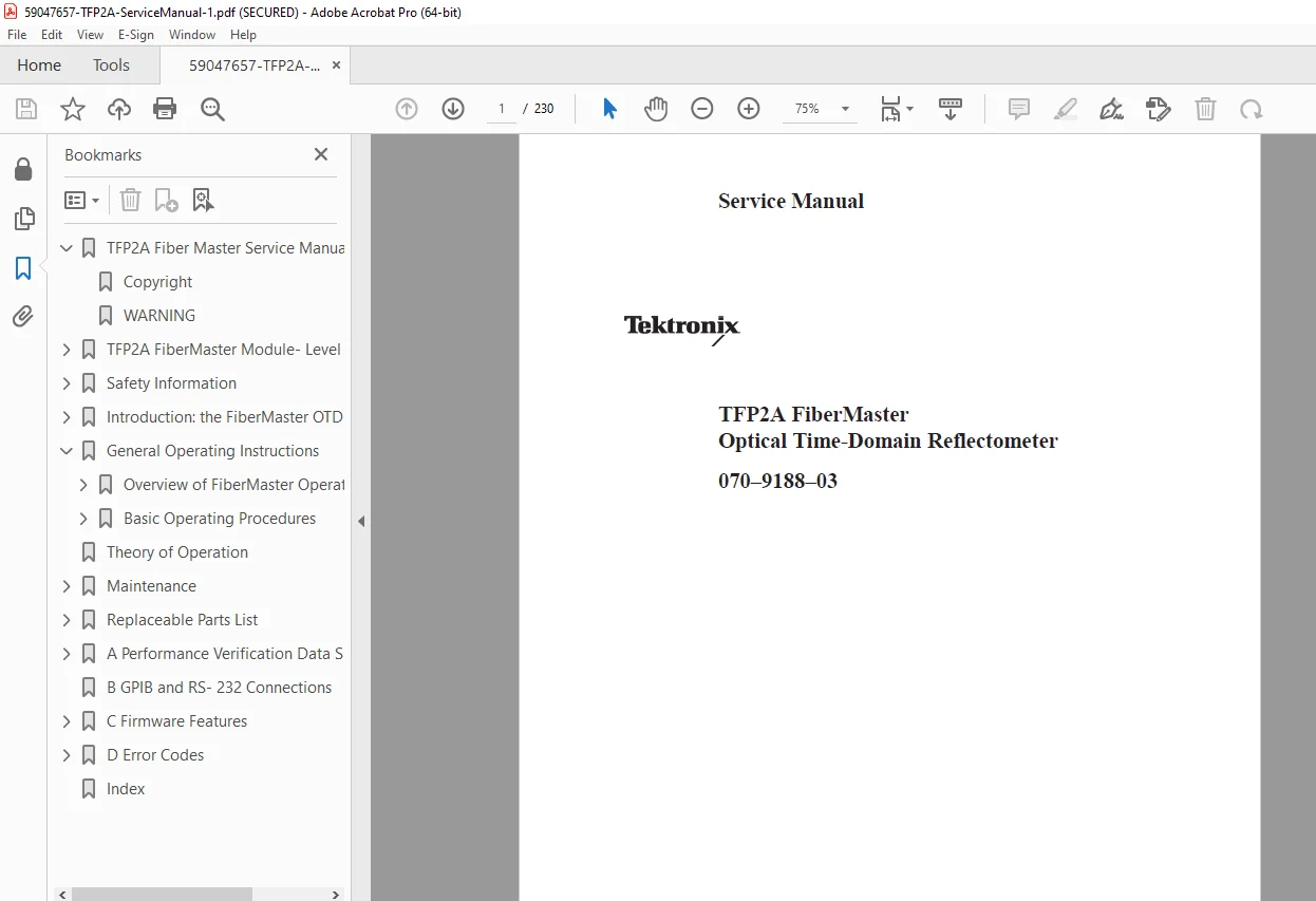
Tektronix TFP2A FiberMaster OTDR Service Manual PDF – Module Level Repair
Original price was: $80.00.$28.95Current price is: $28.95.
Official Tektronix TFP2A FiberMaster OTDR Service Manual (070-9188-03) for optical time domain reflectometer repair and maintenance. This comprehensive module-level service manual covers the complete TFP2A and TFP2AM FiberMaster systems with detailed procedures for all optical modules including FS, FG, FL (singlemode) and FM (multimode) series at 850nm, 1300nm, 1310nm, and 1550nm wavelengths.
Essential for technicians performing fiber optic test equipment service, this Tektronix TFP2A FiberMaster service manual includes complete theory of operation, performance verification procedures, OTDR calibration troubleshooting procedures, adjustment protocols, removal/replacement instructions, and comprehensive parts lists. Features detailed coverage of singlemode multimode fiber testing capabilities, dynamic range testing, dead zone measurements, and optical module replacement procedures. 230 pages of factory documentation for professional FiberMaster optical module service and repair.
Description
Tektronix TFP2A FiberMaster OTDR Service Manual PDF DOWNLOAD – Module Level Repair
IMAGES:
Description
Tektronix TFP2A FiberMaster OTDR Service Manual – Complete Module-Level Repair Documentation
When your Tektronix TFP2A FiberMaster Optical Time-Domain Reflectometer needs service, calibration, or repair, you need the official factory documentation. This is the Official Tektronix TFP2A FiberMaster Service Manual (070-9188-03) – the exact technical guide that certified Tektronix service technicians use for professional fiber optic test equipment service. This comprehensive manual is essential for anyone performing module-level maintenance, OTDR calibration troubleshooting procedures, performance verification, or component replacement on FiberMaster systems.
Complete Coverage for All FiberMaster OTDR Models
This Tektronix TFP2A FiberMaster service manual provides detailed technical documentation for:
- TFP2A (Color monitor mainframe)
- TFP2AM (Monochrome monitor mainframe)
- All optical plug-in modules (singlemode and multimode)
Comprehensive Optical Module Documentation
One of the key strengths of this manual is the complete coverage of all FiberMaster optical module configurations. The TFP2A system accommodates multiple plug-in laser modules for comprehensive singlemode multimode fiber testing across all industry-standard wavelengths:
Singlemode Optical Modules Covered:
- FS1300 – Singlemode 1310nm (Standard range)
- FS1500 – Singlemode 1550nm (Standard range)
- FS1315 – Singlemode Dual wavelength (1310nm/1550nm)
- FG1300 – Singlemode 1310nm (Extended range)
- FG1315 – Singlemode Dual wavelength (1310nm/1550nm)
- FL1300 – Singlemode 1310nm (Long range)
- FL1500 – Singlemode 1550nm (Long range)
- FL1315 – Singlemode Dual wavelength (1310nm/1550nm)
Multimode Optical Modules Covered:
- FM8500 – Multimode Dual wavelength (850nm/1300nm)
- FM1300 – Multimode 1300nm
- FM8513 – Multimode Dual wavelength (850nm/1310nm)
Each optical module section includes complete specifications, installation procedures, FiberMaster optical module replacement steps, and performance verification tests specific to that wavelength and range configuration.
What Makes This OTDR Service Manual Essential
Factory-Level Technical Documentation
- Official Tektronix engineering specifications
- Complete theory of operation for all assemblies
- Professional OTDR calibration troubleshooting procedures
- Detailed block diagrams and signal flow
- Component-level repair information
Performance Verification Procedures
This manual excels in providing comprehensive test procedures to verify your FiberMaster OTDR is operating within factory specifications:
- Clock Frequency Verification – Timebase accuracy testing
- Clock Phase Verification – Signal timing validation
- Front-Panel Loss Testing – Connector loss measurement accuracy
- Dynamic Range Testing – Complete procedures with multiple pulse widths and distance spans
- Dead Zone Measurements:
- Attenuation dead zone verification
- Event dead zone verification
- Displayed Noise Verification – <0.030 dB specifications (FS/FG series)
- Zero Distance Accuracy Testing – Distance measurement calibration
- Vertical System Linearity – Loss measurement accuracy across full range
- Optical Output Amplitude – Laser power verification
Each test includes:
- Required test equipment specifications
- Detailed step-by-step procedures
- Pass/fail criteria
- Troubleshooting guidance for out-of-spec results
Complete Adjustment Procedures
Critical calibration adjustments covered include:
- Control board adjustments (multiple circuits)
- Printer board adjustment
- Display adjustments (focus, brightness, geometry, color convergence)
- Optical module alignments
- All with exact adjustment specifications and procedures
Comprehensive Troubleshooting
- Diagnostic menu navigation
- Troubleshooting flowcharts
- Error code definitions (File System, Flash Memory, LED, Phase 1/2 errors)
- Symptom-based diagnosis
- Component-level fault isolation
📋 Complete Manual Contents
Official Tektronix Service Manual (230 Pages)
Safety Information
- Comprehensive safety warnings and precautions
- Definition of terms and symbols
- Power source requirements
- Grounding requirements
- Laser radiation safety (Class 1 laser product)
- Electrical safety guidelines
- Service personnel safety requirements
Chapter 1: Introduction – The FiberMaster OTDR (Pages 1-1 to 1-36)
Product Description
- OTDR technology overview
- FiberMaster capabilities
- CRT display operation
- Time-domain reflectometry principles
- Light pulse reflection analysis
- Fiber fault detection methodology
- Splice loss measurement
- Event identification
Using This Manual
- Strategy for servicing FiberMaster systems
- Manual structure and organization
- Manual conventions and symbols
- Documentation navigation guide
Warranty Information
- Warranty coverage details
- Terms and conditions
- Service exclusions
Tektronix Service
- Contact information
- Service center locations
- Technical support resources
- Parts ordering procedures
Complete Specifications
Table 1-1: Display Range – Vertical System
- Loss measurement range specifications
- Resolution specifications
- Accuracy specifications
Table 1-2: Display Range – Horizontal System
- Distance range specifications
- Resolution specifications
- Pulse width options
Table 1-3: Display
- CRT specifications
- Display resolution
- Color/monochrome characteristics
- Screen dimensions
Table 1-4: Keyboard
- Front panel controls
- Key functions
- Interface specifications
Table 1-5: Hardcopy
- Printer specifications
- Print resolution
- Paper specifications
Table 1-6: Mass Storage
- Disk drive specifications
- Storage capacity
- File formats supported
Table 1-7: Operational Characteristics
- Operating temperature range
- Warm-up time
- Measurement capabilities
- Processing speed
Table 1-8: Physical Characteristics
- Dimensions (length, width, height)
- Weight specifications (with various configurations)
- Mounting requirements
Table 1-9: Environmental Characteristics
- Operating temperature: 0°C to +50°C
- Storage temperature: -40°C to +71°C
- Humidity specifications
- Altitude specifications
- EMC compliance (EN 50081-1, EN 50082-1)
- FCC Class A compliance
Optical Module Specifications
Each optical module has a dedicated specification table:
Table 1-10: FS1300 Singlemode Optical Module
- Wavelength: 1310nm
- Dynamic range specifications
- Dead zone specifications
- Distance range
- Pulse width options
Table 1-11: FS1500 Singlemode Optical Module
- Wavelength: 1550nm
- Performance specifications
- Range capabilities
Table 1-12: FS1315 Singlemode Optical Module
- Dual wavelength: 1310nm/1550nm
- Independent channel specifications
- Switching characteristics
Table 1-13: FG1300 Singlemode Optical Module
- Extended range 1310nm
- Enhanced dynamic range
- Long-distance capabilities
Table 1-14: FG1315 Singlemode Optical Module
- Extended range dual wavelength
- 1310nm/1550nm specifications
Table 1-15: FL1300 Singlemode Optical Module
- Long range 1310nm
- Maximum distance capabilities
- High dynamic range
Table 1-16: FL1500 Singlemode Optical Module
- Long range 1550nm
- Premium performance specifications
Table 1-17: FL1315 Singlemode Optical Module
- Long range dual wavelength
- 1310nm/1550nm maximum capabilities
Table 1-18: FM8500 Multimode Optical Module
- Dual wavelength: 850nm/1300nm
- Multimode fiber specifications
- 62.5/125μm and 50/125μm fiber support
Table 1-19: FM1300 Multimode Optical Module
- Single wavelength: 1300nm
- Multimode specifications
Table 1-20: FM8513 Multimode Optical Module
- Dual wavelength: 850nm/1310nm
- Comprehensive multimode testing
Accessories and Options
Table 1-21: Mainframe Options
- TFP2A (color CRT)
- TFP2AM (monochrome CRT)
- AC/DC power options
Table 1-22: Standard Accessories
- Power cords
- User manuals
- Optical connectors
- Carrying case
Table 1-23: Optional Accessories
- Additional optical adapters
- Launch cables
- Cleaning supplies
- Storage media
Table 1-24: System Options
- Internal printer option
- Disk drive configurations
- GPIB interface
- RS-232 interface
Table 1-25: System Multimode Options
- FM8500, FM1300, FM8513 configurations
- Dual-wavelength vs. single-wavelength choices
Table 1-26: System Singlemode Options
- FS, FG, FL series configurations
- Range and wavelength combinations
Table 1-27: Option Accessories
- Optical test cables
- Reference reflectors
- Attenuators
- Adapter kits
Unpacking and Preparation for Use
- Unpacking procedures
- Initial inspection checklist
- Installation requirements
- Installing Optical Modules (page 1-30)
- Module installation procedures
- Connector types and adapters
- Module recognition and configuration
- Environmental setup requirements
- Power connection procedures
- Initial power-on sequence
Storage
- Long-term storage procedures
- Environmental requirements
- Optical module protection
- Battery maintenance (if applicable)
Repacking for Shipment
- Proper packaging procedures
- Protection requirements
- Shipping precautions
Recalibration
- Recalibration interval recommendations
- Factory calibration services
- Calibration certificate information
Chapter 2: General Operating Instructions (Pages 2-1 to 2-8)
Overview of FiberMaster Operation
- Basic OTDR principles
- Measurement process
- Display interpretation
- Data acquisition overview
The Acquisition Screen
- Screen layout and elements
- Trace display
- Cursor functions
- Measurement readouts
- Menu navigation
- Softkey functions
Basic Operating Procedures
- Power-on sequence
- Optical module selection
- Parameter setup
- Fiber testing procedures
- Measurement techniques
- Data storage
- Report generation
Chapter 3: Theory of Operation (Pages 3-1 to 3-5)
Complete circuit-level theory for all major assemblies:
A1 – Control Assembly
- Host Processor
- CPU architecture
- Memory management
- Operating system
- Control algorithms
- Display Processor
- Graphics generation
- CRT control
- Display memory
- Timebase
- Clock generation
- Timing circuits
- Distance-to-time conversion
- Signal Averager
- Averaging algorithms
- Noise reduction
- Signal processing
A2 – Front Panel Assembly
- Front Panel
- Keyboard interface
- Control switches
- LED indicators
- User interface circuits
A3 – Power Supply
- AC input circuits
- DC voltage generation
- Voltage regulation
- Protection circuits
- Distribution system
A4 – Interconnect
- Interconnect Board
- Signal routing
- Bus architecture
- Inter-board communications
- Connector specifications
A5 – Module Support
- Digital Interface and Cooler Power Supplies
- Optical module interface
- Laser cooler circuits
- Temperature control
- Mask Generator
- Measurement masks
- Pass/fail testing
- Strobe Continuation
- Trigger circuits
- Timing control
A6 – Printer Assembly
- Printer Power Distribution
- Printer interface
- Power circuits
- Control signals
A7 – Display Assembly
- Display
- CRT operation
- High voltage circuits
- Video amplifiers
- Deflection circuits
- Focus control
- Brightness control
A20/A30 – Optical Plug-in Modules
- Laser diode circuits
- Temperature control (TEC)
- Optical coupling
- Detector circuits
- Amplification
- Signal conditioning
- Module-specific architectures
Chapter 4: Maintenance (Pages 4-1 to 4-103)
This is the most comprehensive section, essential for hands-on service work.
Product Service (Page 4-1)
- Service safety precautions
- Required qualifications
- Service strategy
Static-Sensitive Components (Page 4-2)
- ESD precautions
- Grounding procedures
- Anti-static handling
- Component protection
Inspection and Cleaning Procedures (Pages 4-3 to 4-7)
Table 4-1: External Inspection Checklist (Page 4-3)
| Inspection Item | Check For | Action |
|---|---|---|
| External Surfaces | Damage, dirt | Clean, document |
| Optical Connectors | Contamination, damage | Clean, replace |
| Front Panel | Control operation | Test, repair |
| Cooling Vents | Blockage | Clean |
Exterior Inspection (Page 4-3)
- Visual inspection procedures
- Damage assessment
- Connector inspection
Exterior Cleaning (Page 4-4)
- Approved cleaning materials
- Case cleaning procedures
- Control cleaning
Optical-Fiber Cleaning (Pages 4-4 to 4-6)
- CRITICAL PROCEDURE for accurate measurements
- Fiber endface cleaning
- Connector cleaning
- Cleaning materials (isopropyl alcohol, lint-free wipes)
- Inspection after cleaning
- Contamination types and removal
Table 4-2: Internal Inspection Checklist (Page 4-6)
| Component | Inspection Focus | Frequency |
|---|---|---|
| PC Boards | Solder joints, components | Annual |
| Connectors | Corrosion, tension | Annual |
| Cooling Fan | Operation, noise | Every 6 months |
| Power Supply | Voltages, heat | Annual |
Interior Inspection (Page 4-6)
- Cover removal safety
- Internal visual inspection
- Component assessment
- Cable and connector check
Interior Cleaning (Page 4-7)
- Board cleaning procedures
- Compressed air usage
- Contact cleaning
Lubrication (Page 4-7)
- Mechanical assemblies
- Lubrication points
- Recommended lubricants
Terminal Interface (Pages 4-8 to 4-9)
- GPIB interface testing
- RS-232 interface testing
- Communication verification
- Protocol testing
Functional Tests (Pages 4-10 to 4-15)
Mainframe Checks (Pages 4-10 to 4-15)
- Power-on self-test (POST)
- Display functionality
- Keyboard operation
- Printer operation
- Disk drive operation
- Interface testing
- Diagnostic menu access
- System verification
Performance Verification (Pages 4-16 to 4-59)
This extensive section provides complete test procedures for verifying FiberMaster meets factory specifications. Each test includes equipment required, setup procedures, measurement steps, and acceptance criteria.
Equipment Required (Page 4-16)
- Digital multimeter specifications
- Optical power meter
- Test fibers (various lengths)
- Reference reflectors
- Attenuators
- Adapters and cables
Clock Frequency (Pages 4-16 to 4-17)
- Timebase accuracy test
- Frequency measurement procedure
- Specification: ±0.01%
- Troubleshooting out-of-spec results
Verify Clock Phase (Pages 4-17 to 4-18)
- Phase relationship testing
- Signal timing verification
- Adjustment if necessary
Front-Panel Loss (Pages 4-18 to 4-20)
- Connector loss measurement
- Front panel optical path testing
- Acceptance criteria
- Troubleshooting high loss
Dynamic Range (Pages 4-20 to 4-32)
- Most comprehensive test in manual
- Multiple test configurations
- Table 4-3: Dynamic Range Pulse Width and Distance Span (Page 4-30)
| Module Type | Pulse Width | Distance Span | Min. Dynamic Range |
|---|---|---|---|
| FS1300 | 10μs | 256 km | 28 dB |
| FG1300 | 10μs | 256 km | 32 dB |
| FL1300 | 10μs | 512 km | 36 dB |
| FS1500 | 10μs | 256 km | 30 dB |
| FL1500 | 10μs | 512 km | 38 dB |
| FM8500 (850nm) | 1μs | 20 km | 18 dB |
| FM8500 (1300nm) | 1μs | 20 km | 20 dB |
- Test fiber requirements (long, low-loss fiber)
- Measurement procedures
- SNR (Signal-to-Noise Ratio) calculation
- Pass/fail determination
- Documentation requirements
Dead Zone (Attenuation) (Pages 4-32 to 4-34)
- Attenuation dead zone definition
- Measurement procedure using reference reflector
- Specification by module and pulse width
- Troubleshooting excessive dead zones
Dead Zone (Event) (Pages 4-34 to 4-36)
- Event dead zone definition
- Measurement using reference reflectors
- Specification by module
- Diagnosis of specification failures
Displayed Noise <0.030 dB (FS/FG series only) (Pages 4-36 to 4-38)
- Noise floor measurement
- FS and FG series requirements
- Test procedure
- Acceptance criteria
Zero Distance Accuracy (Pages 4-38 to 4-40)
- Distance measurement calibration
- Front panel reference measurement
- Table 4-4: Distance Accuracy Tolerance
| Distance Span | Accuracy Tolerance |
|---|---|
| 0-10 km | ±1 meter |
| 10-100 km | ±0.01% |
| 100-512 km | ±0.02% |
- Adjustment procedures if out of tolerance
Vertical System Linearity (Pages 4-40 to 4-56)
- Loss measurement accuracy across full range
- Table 4-5: Small Linearity Pulse Width Settings (Page 4-51)
- Table 4-6: Loss Measurement Accuracy Pulse Width Settings (Page 4-53)
- Variable attenuator testing
- Multiple measurement points
- Linearity calculation
- Specification: ±0.05 dB typical
- Troubleshooting non-linearity
Optical Output Amplitude (Pages 4-56 to 4-60)
- Laser output power measurement
- Power meter requirements
- Measurement procedure per module
- Specification ranges by module
- Low power troubleshooting
Adjustments (Pages 4-60 to 4-69)
Control Board Adjustments (Pages 4-60 to 4-62)
- Multiple adjustment points on control assembly
- Trimmer potentiometer locations
- Adjustment procedures with test equipment
- Specifications for each adjustment
- Interaction between adjustments
Printer Board Adjustment (Pages 4-62 to 4-64)
- Printer alignment
- Print quality optimization
- Test pattern printing
Display Adjustments (Pages 4-64 to 4-69)
- Focus Adjustment
- CRT focus optimization
- Center and edge focus
- Brightness and Contrast
- Optimal viewing adjustment
- Background level
- Geometry Adjustments
- Horizontal size
- Vertical size
- Horizontal position
- Vertical position
- Pincushion correction
- Trapezoid correction
- Color Convergence (TFP2A color models only)
- Red/Green/Blue alignment
- Screen center convergence
- Corner convergence
- Test patterns for convergence
Troubleshooting and Diagnostics (Pages 4-70 to 4-74)
Using the Diagnostics Menus (Pages 4-70 to 4-71)
- Accessing diagnostic mode
- Menu navigation
- Available diagnostic tests
- Test result interpretation
Troubleshooting Flowchart (Pages 4-71 to 4-74)
- Symptom-based diagnosis
- Decision trees for common problems:
- No power
- No display
- Display problems
- Measurement errors
- Optical module not recognized
- Printer problems
- Disk drive problems
- Interface problems
- Component-level fault isolation
- Repair vs. replace decisions
Removal and Replacement Procedures (Pages 4-75 to 4-103)
Table 4-7: Tools Required for Module-Level Maintenance and Repair (Page 4-75)
| Tool | Specification | Use |
|---|---|---|
| Screwdrivers | Phillips #1, #2; Flat 1/8″, 3/16″ | Cover removal, board mounting |
| Hex drivers | 3/32″, 1/8″, 5/32″ | Panel fasteners |
| Nut drivers | 1/4″, 5/16″, 3/8″ | Hardware removal |
| Torx drivers | T-10, T-15 | Special fasteners |
| Needle-nose pliers | Small | Connector removal |
| Tweezers | ESD-safe | Small component handling |
| Torque wrench | 5-50 in-lb range | Critical fasteners |
| ESD wrist strap | 1 megohm | Static protection |
Each removal/replacement procedure includes:
- Required tools
- Safety precautions
- Step-by-step disassembly
- Photos/diagrams
- Component identification
- Reassembly steps
- Verification procedures
- Torque specifications
Covers and Front Panel (Pages 4-77 to 4-78)
- Top cover removal (multiple screws)
- Bottom cover removal
- Side panel removal
- Front panel assembly removal
- Keyboard removal
- Display bezel removal
Back-Panel Assembly and Plug-In Optical Modules (Pages 4-79)
- Rear panel removal
- Optical module removal procedures
- Module connector disconnection
- Module installation
- Module recognition verification
Control Board (Pages 4-80 to 4-81)
- Host processor board location
- Cable and connector disconnection (labeled diagrams)
- Board mounting removal
- Board removal from chassis
- Installation in reverse order
- Connector reconnection verification
- POST verification
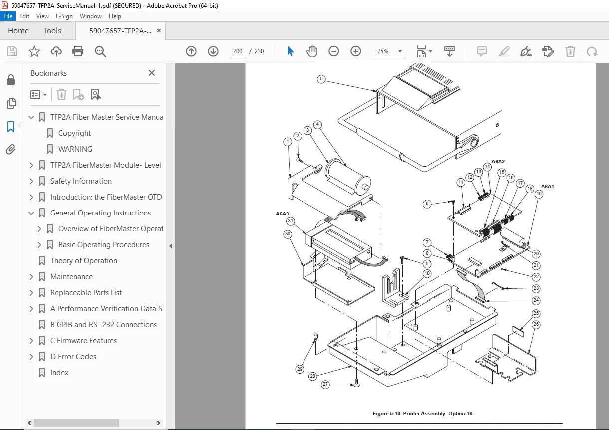
Printer Tray and Printer (Pages 4-82)
- Printer access
- Tray removal
- Printer mechanism removal
- Cable routing
- Installation and alignment
- Test print verification
CRT, Color Shutter/Monochrome Filter, and Display Board (Pages 4-83 to 4-86)
- HIGH VOLTAGE WARNING
- CRT discharge procedure (safety critical)
- Display board removal
- CRT neck board removal
- CRT mounting removal
- Color shutter removal (TFP2A)
- Monochrome filter removal (TFP2AM)
- Installation procedures
- Display adjustment after replacement
PSI Power Supply (AC only) (Pages 4-87 to 4-88)
- AC input power supply
- Location and mounting
- AC cord and fuse replacement
- Removal procedure
- Installation and testing
- Voltage verification
IPD Power Supply and DC Power Option (Pages 4-89 to 4-94)
- Internal power distribution board
- DC voltage outputs
- DC power option installation (for vehicle operation)
- Removal and replacement
- Multiple voltage rail testing
- Protection circuit verification
MDI Power Supply and DC Power Option (Pages 4-95 to 4-97)
- Module distribution interface power
- Optical module power
- TEC cooler power
- Removal and installation
- Voltage testing
Disk Drive (Page 4-98)
- 3.5″ floppy drive
- Mounting removal
- Cable disconnection
- Drive replacement
- Format verification
Module Support Board (Page 4-99)
- Optical interface board
- Cooler control circuits
- Removal and replacement
- Testing after installation
Interconnect Board (Page 4-100)
- System bus board
- Signal routing
- Removal procedure
- Installation and verification
Fan (Pages 4-101 to 4-102)
- Cooling fan location
- Power connection
- Mounting removal
- Fan replacement
- Airflow verification
- Noise check
Power Switch, Wire Set, and Line Filter (Pages 4-103)
- Front panel power switch
- AC line filter
- Internal wiring harness
- Replacement procedures
Chapter 5: Replaceable Parts List (Pages 5-1 to 5-end)
Parts Ordering Information (Page 5-1)
- How to order parts from Tektronix
- Part number format
- Serial number requirements
- Contact information
Module Replacement (Page 5-1)
- When to replace vs. repair
- Module exchange program
- Calibration after module replacement
Using the Replaceable Parts List (Pages 5-2 to end)
Tektronix Part Number
- Part numbering system explained
- Suffix codes
- Revision levels
Serial/Model No.
- Applicability by serial number
- Model-specific parts
- Running changes
Name and Description
- Component identification
- Assembly descriptions
- Reference designators
Mfr. Code and Part Number
- Manufacturer codes
- Original manufacturer part numbers
- Substitution information
Complete Parts Lists include:
- Main chassis assembly
- Control board components
- Power supply components
- Display assembly components
- Optical modules (FS, FG, FL, FM series)
- Cables and interconnects
- Mechanical hardware
- Accessories
- Consumables
Appendix A: Performance Verification Data Sheets (Pages A-1 to A-5)
Blank forms for recording calibration results:
Optical Test Summary Data Sheet – FS1315 Singlemode (Page A-2)
- Test date and technician
- Serial number
- All performance tests with pass/fail checkboxes
- Measurement result fields
- Notes section
Optical Test Summary Data Sheet – FG1315 Singlemode (Page A-3)
- Similar format for FG series
- Extended range specifications
Optical Test Summary Data Sheet – FL1315 Singlemode (Page A-4)
- Long range specifications
- Enhanced dynamic range tests
Optical Test Summary Data Sheet – FM8513 Multimode (Page A-5)
- Multimode specific tests
- Dual wavelength verification
- 850nm and 1310nm tests
Appendix B: GPIB and RS-232 Connections (Pages B-1 to B-2)
Table B-1: GPIB Connections (Page B-1)
| Pin | Signal | Function | Direction |
|---|---|---|---|
| 1 | DIO1 | Data I/O Bit 1 | Bidirectional |
| 2 | DIO2 | Data I/O Bit 2 | Bidirectional |
| … | … | … | … |
| 24 | GND | Ground | – |
- Complete pin-out
- Cable specifications
- Interface requirements
- Address setting
Table B-2: RS-232 Connections (DCE) (Page B-2)
| Pin | Signal | Function |
|---|---|---|
| 2 | TXD | Transmit Data |
| 3 | RXD | Receive Data |
| 4 | RTS | Request to Send |
| 5 | CTS | Clear to Send |
| 7 | GND | Signal Ground |
- Serial interface wiring
- Baud rate settings
- Handshaking protocol
- Cable requirements
Appendix C: Firmware Features (Pages C-1 to C-2)
Table C-1: Firmware Versions and Features (Page C-2)
| Version | Release Date | New Features | Bug Fixes |
|---|---|---|---|
| 1.0 | Initial | Base functionality | N/A |
| 1.1 | … | Enhanced averaging | Fixed display issue |
| … | … | … | … |
- Firmware revision history
- Feature additions by version
- Compatibility information
- Update procedures
Appendix D: Error Codes (Pages D-1 to D-5)
Table D-1: File System Error Codes (Page D-1)
| Code | Message | Cause | Remedy |
|---|---|---|---|
| FS01 | Disk Full | No space | Delete files or format |
| FS02 | File Not Found | Missing file | Check filename |
| FS03 | Write Protected | Disk protected | Remove protection |
| … | … | … | … |
Table D-2: Flash Memory Error Codes (Page D-3)
| Code | Description | Action |
|---|---|---|
| FM01 | Write Failure | Replace memory |
| FM02 | Verify Error | Reprogram |
| … | … | … |
Table D-3: LED Error Codes (Page D-4)
- Power-on self-test LED indicators
- Blink patterns and meanings
- Hardware failure indications
Table D-4: Phase 1 Error Codes (Page D-5)
- Boot sequence errors
- Hardware initialization failures
Table D-5: Phase 2 Error Codes (Page D-5)
- Operating system errors
- Application software errors
- User-correctable vs. service-required errors
📄 File Details
- Manual Name: Tektronix TFP2A FiberMaster OTDR Service Manual
- Document Number: 070-9188-03
- Models Covered:
- TFP2A (Color CRT mainframe)
- TFP2AM (Monochrome CRT mainframe)
- All optical modules: FS1300, FS1500, FS1315, FG1300, FG1315, FL1300, FL1500, FL1315, FM8500, FM1300, FM8513
- Publication Date: First Printing April 1997, Revised October 2000
- Copyright: 1997 Tektronix, Inc.
- PDF Quality: Good quality scan, searchable text, includes all diagrams and tables
- Pages: 230
- Language: English
- File Size: 2.4 MB
- Format: PDF 1.3, optimized
Who Needs This Manual?
This official Tektronix service manual is essential for:
- Fiber Optic Test Equipment Technicians (professional OTDR service)
- Telecommunications Service Engineers (field testing equipment maintenance)
- Tektronix Authorized Service Centers (factory-level repair capability)
- Network Installation Companies (in-house equipment calibration)
- Fiber Optic System Integrators (test equipment maintenance)
- Military/Government Agencies (equipment sustainment programs)
- University/Research Labs (advanced optical testing equipment)
- Calibration Laboratories (OTDR calibration services)
- Biomedical Equipment Technicians (expanding to optical test equipment)
What Makes the TFP2A FiberMaster Special
The Tektronix TFP2A FiberMaster represents professional-grade OTDR technology:
- Modular Optical System – Up to four wavelengths in one instrument
- Singlemode and Multimode Capable – Comprehensive fiber testing
- Wide Dynamic Range – 18 dB to 38 dB depending on module
- Long Distance Capability – Up to 512 km with FL series modules
- Dual Wavelength Modules – Test both wavelengths without module swap
- Professional CRT Display – High-resolution trace display
- Built-in Printer – Immediate hardcopy documentation
- Disk Storage – Save and recall test results
- GPIB/RS-232 Interfaces – Remote control and data transfer
Why This Service Manual is Critical
Factory-Level Repair Capability:
- Official Tektronix engineering documentation (not third-party)
- Complete OTDR calibration troubleshooting procedures
- Component-level repair information
- Theory of operation for understanding system function
- Professional fiber optic test equipment service procedures
Comprehensive Performance Verification:
- Every critical parameter tested
- Detailed test procedures with acceptance criteria
- Required test equipment specified
- Troubleshooting guidance for out-of-spec results
- Data sheets for documentation
Complete Optical Module Coverage:
- All FiberMaster optical module variants documented
- Singlemode modules (FS, FG, FL series at 1310nm, 1550nm)
- Multimode modules (FM series at 850nm, 1300nm, 1310nm)
- Module-specific specifications and tests
- FiberMaster optical module replacement procedures
Prevent Costly Mistakes:
- Correct disassembly sequences prevent damage
- Proper ESD handling protects sensitive components
- Adjustment procedures require this documentation
- Calibration cannot be performed without this manual
- Parts identification prevents ordering errors
Common Service Scenarios Covered:
✅ No Display – Power supply, display board, CRT troubleshooting
✅ Optical Module Not Recognized – Interface board, module connector diagnosis
✅ Inaccurate Measurements – Calibration verification and adjustment
✅ Low Dynamic Range – Laser power, detector, amplifier troubleshooting
✅ Excessive Dead Zones – Optical path, detector recovery issues
✅ Distance Measurement Errors – Clock frequency calibration
✅ Loss Measurement Errors – Vertical linearity adjustment
✅ Printer Malfunctions – Printer board, mechanism service
✅ Disk Drive Problems – Drive replacement, format issues
✅ Interface Communication Errors – GPIB/RS-232 troubleshooting
✅ No Laser Output – Module diagnostics, replacement
✅ Temperature Control Issues – TEC cooler, module support board
⚠️ Important Notice
This is a professional-grade factory service manual intended for qualified service technicians with experience in electronic test equipment repair. Working on optical test equipment requires knowledge of:
- Laser safety (Class 1 laser product)
- High-voltage CRT circuits
- ESD-sensitive components
- Optical fiber handling
- Precision calibration procedures
- Electronic troubleshooting
Always follow safety procedures, including:
- Proper CRT discharge before handling
- ESD precautions for all circuit boards
- Laser safety when handling optical modules
- Electrical isolation when servicing power supplies
Calibration Note: After significant repairs (optical module replacement, control board replacement, major adjustments), complete performance verification should be performed to ensure the instrument meets specifications. Some adjustments require precision test equipment not typically available outside dedicated service facilities.
Key Benefits:
✅ Official Tektronix Factory Documentation – Authentic service procedures
✅ Complete Module-Level Service – Component replacement capability
✅ 230 Pages of comprehensive technical information
✅ All Optical Modules Covered – FS, FG, FL, FM series (11 modules total)
✅ Singlemode and Multimode – Complete wavelength coverage
✅ Performance Verification Procedures – Calibration and testing
✅ OTDR Calibration Troubleshooting – Systematic diagnosis
✅ Dynamic Range Testing – Critical OTDR parameter verification
✅ Dead Zone Measurement – Attenuation and event dead zones
✅ Adjustment Procedures – Control, display, printer adjustments
✅ Complete Parts Lists – Accurate parts identification and ordering
✅ Error Code Tables – Quick fault diagnosis
✅ Removal/Replacement Procedures – Step-by-step disassembly
✅ Searchable PDF – Find information quickly
✅ Calibration Data Sheets – Document performance verification
✅ Instant Download – Start service work immediately
Maintain Critical Test Equipment
The Tektronix TFP2A FiberMaster is professional-grade optical test equipment used in telecommunications, data centers, military installations, and research facilities worldwide. Proper maintenance and calibration ensure accurate fiber characterization, fault location, and loss measurement. This service manual provides the factory procedures to keep your FiberMaster OTDR operating at peak performance, extend equipment life, and maintain measurement integrity.
Whether you’re performing routine maintenance, troubleshooting measurement errors, replacing optical modules, or conducting complete performance verification, this manual is your essential resource for professional fiber optic test equipment service.
Instant Digital Delivery: Receive your PDF manual immediately after purchase. No shipping delays, no waiting. Download and start your service work right away.