
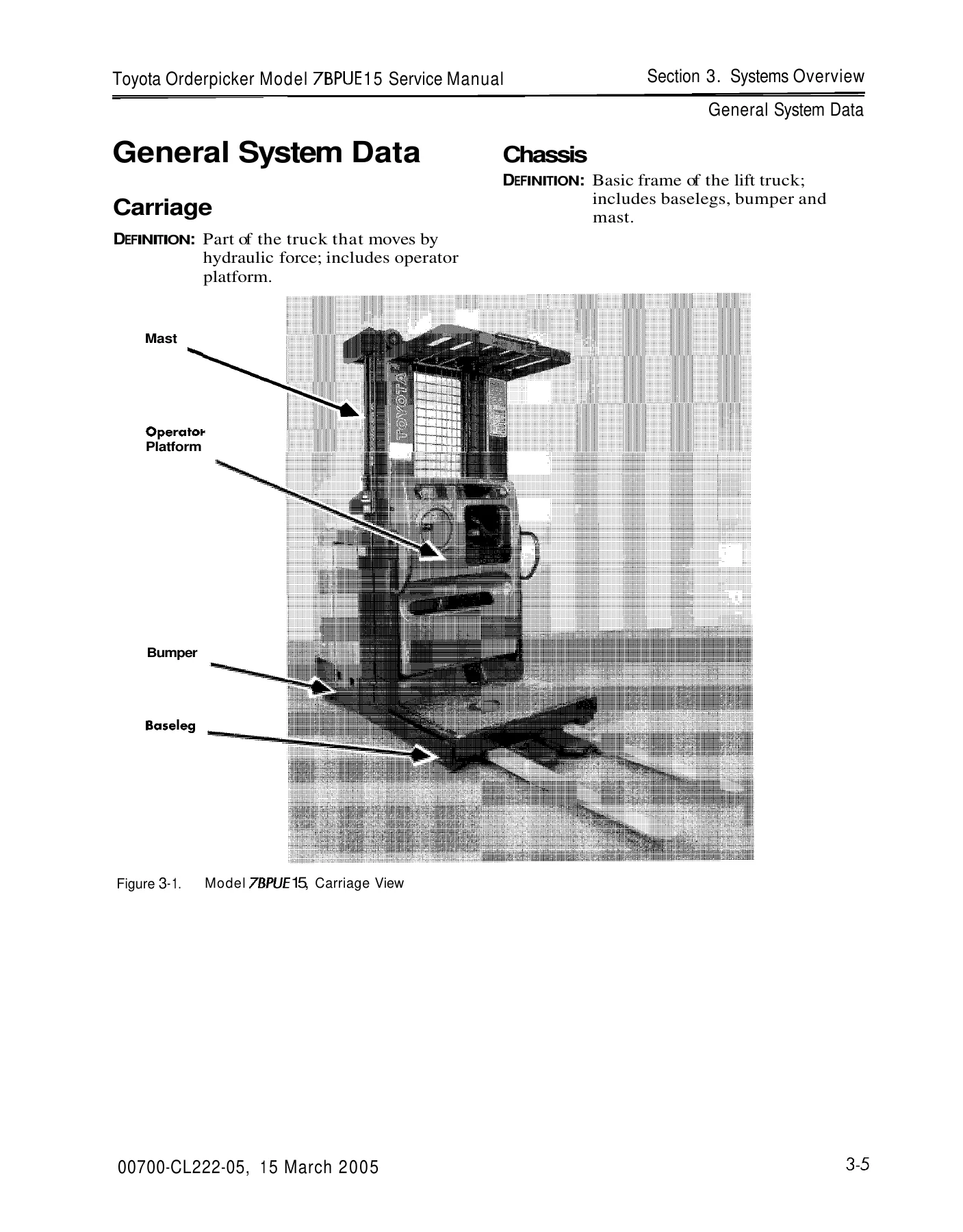
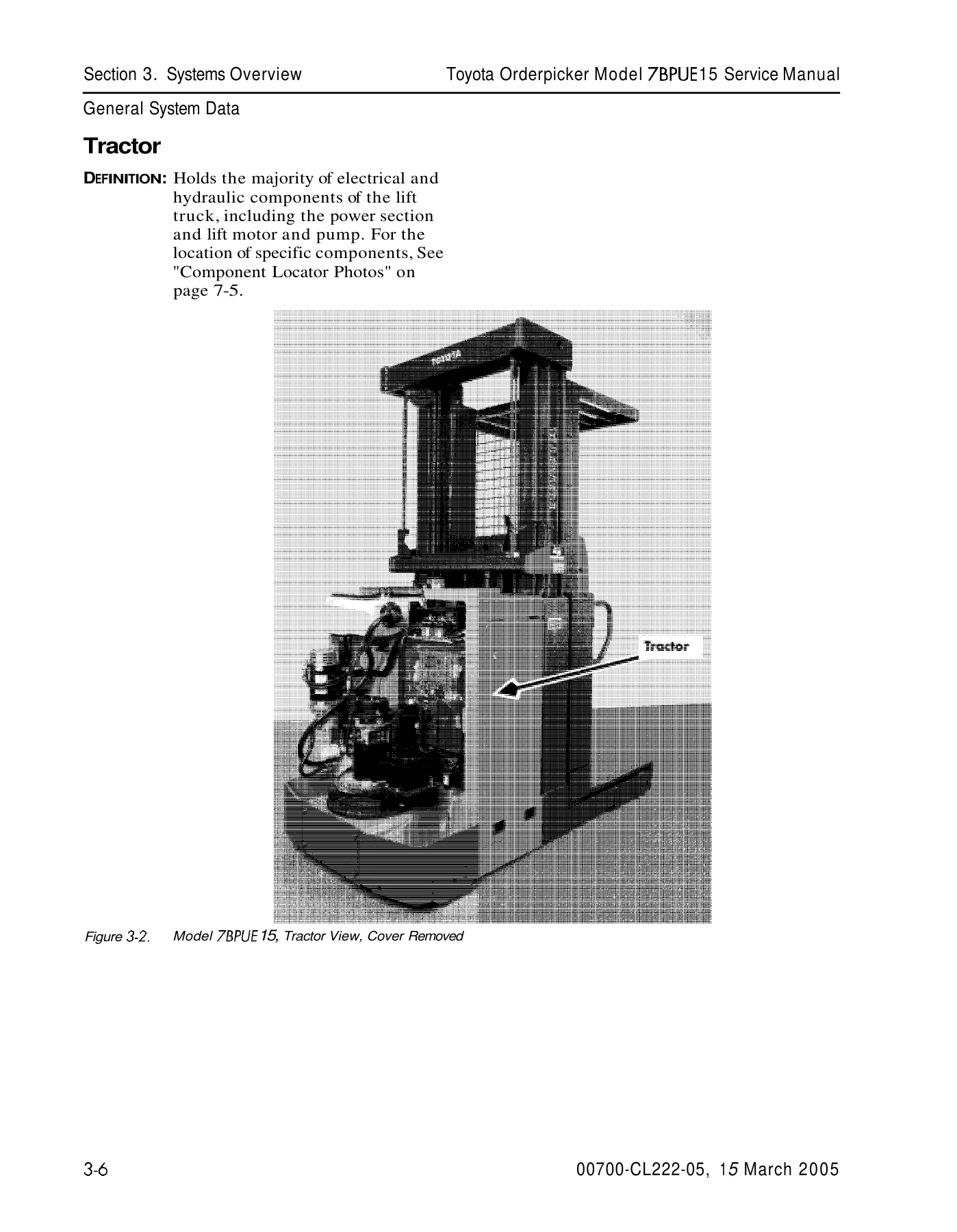
Toyota 7BPUE15 Orderpicker Service Manual – Serial 80001 Up (2005)
Original price was: $39.95.$24.95Current price is: $24.95.
Complete Toyota 7BPUE15 Orderpicker Service Manual covering serial numbers 80,001 and up. This 413-page PDF includes troubleshooting, component procedures, electrical and hydraulic schematics, wire guidance setup, and planned maintenance intervals for the 24-volt electric orderpicker.
Description
Toyota 7BPUE15 Orderpicker Service Manual – Serial 80001 and Up
This Toyota 7BPUE15 Orderpicker Service Manual is the complete service documentation published by Toyota Industrial Equipment for the 7BPUE15 24-volt electric orderpicker, covering trucks from serial number 80,001 and up. Issued under document number 00700-CL222-05 and dated 15 March 2005, this manual gives technicians, fleet managers, and shop owners the procedures and specifications needed to maintain, diagnose, and repair the 7BPUE15 correctly.
Whether you are performing scheduled maintenance, chasing an intermittent fault code, rebuilding a drive unit, or setting up wire guidance, this Toyota 7BPUE15 service manual provides the step-by-step procedures, torque values, wiring diagrams, and hydraulic schematics to get the job done properly.
File Details
- Manual Type: Service Manual
- Brand: Toyota
- Model: 7BPUE15 Orderpicker
- Serial Number Range: 80,001 and up
- Document Number: 00700-CL222-05
- Publication Date: 15 March 2005
- Publisher: Toyota Industrial Equipment
- Language: English
- Page Count: 413 pages
- File Format: PDF
Chapters Covered
- How to Use This Manual – Manual design, map of the manual, START page, page revision record
- Safety – Definitions, general safety, battery safety, static safety, jacking safety, tie-down for transport, towing a disabled unit, welding safety
- Systems Overview – Vehicle specifications, general system data, installation instructions, wire guidance, cold storage, UL Label EE, special tools
- Planned Maintenance – Maintenance guidelines, Interval 1 (daily/eight hours), Interval 2 (every 6 months or 500 hours / severe usage 3 months or 250 hours), Interval 3 (every year or 1500 hours)
- Troubleshooting – Electrical troubleshooting guidelines, shorts to frame test, troubleshooting wiring problems, switches (general), electric motor tests, battery discharge indicator (BDI), contactors, fuses, hydraulic troubleshooting guidelines, definitions, electrical connector locator chart, programmable maintenance tool, drive unit troubleshooting guide, troubleshooting flowcharts, symptom tables for hydraulic functions, travel functions, and electrical symptoms
- Codes and Tests – Operator display messages, maintenance mode, operator display fault codes
- Component Procedures – Covers and finish, steering and controls, drive and brake, electrical components, hydraulic components, mast section
- Wire Guidance – System overview, install kit components, set-up procedure, codes and tests, tests, general troubleshooting, troubleshooting in FlashWare, theory of operation
- Theory of Operation – Battery plugged in, key switch on, closing deadman switches, travel, steering, lift/lower, primary memory, pinout matrix, firmware configuration
- Appendix – Lubrication specification chart, torque charts (standard ferrous, standard brass, metric), decimal equivalent chart, standard/metric conversions, electrical schematics, hydraulic schematic
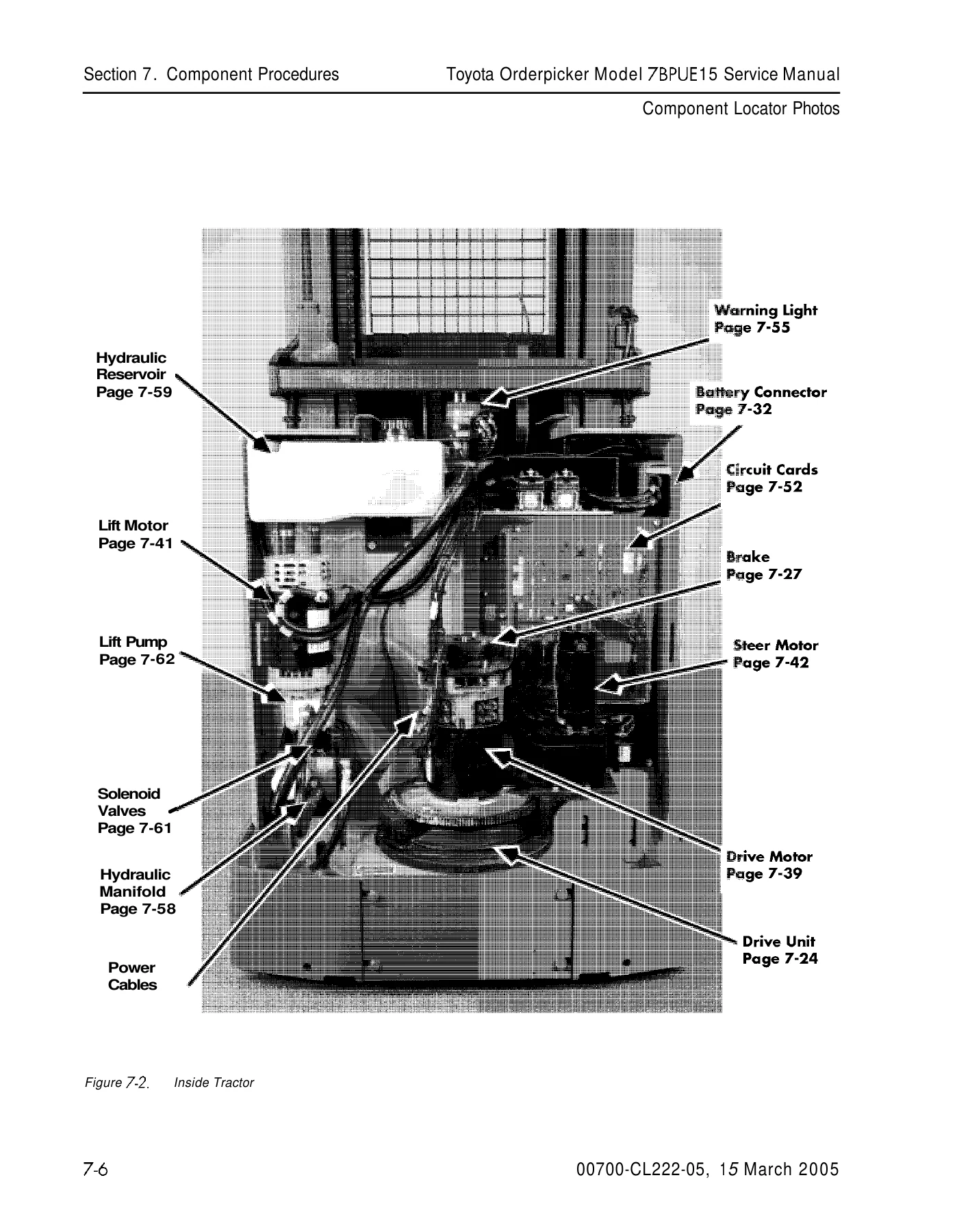
This Toyota 7BPUE15 Orderpicker Service Manual goes far beyond routine maintenance. The component procedures chapter walks through removal, installation, disassembly, assembly, inspection, and adjustment for major systems including the drive unit, brake, drive motor, lift motor, steer motor, traction power amplifier, contactors, fuses, hydraulic manifold, hydraulic reservoir, solenoid valves, lift pump, lift pressure relief valve, side cylinder, center cylinder, flow control valve, mast sections, carriage assemblies, lift chains, forks, load wheels, and skid pads. The wire guidance chapter provides the complete install kit component list, set-up procedure, learn guide wire frequency and offset procedures, guidance check, fault codes, and troubleshooting steps for trucks equipped with the wire guidance option.
The Theory of Operation chapter traces signal flow through the electrical and hydraulic systems for each operating condition: battery plugged in, key switch on, deadman switches closed, travel, steering, lift, and lower. It includes a detailed pinout matrix listing functions and normal voltages for terminals and harness connector pins. The appendix provides lubrication specifications, standard and metric torque charts, decimal equivalents, conversion tables, electrical schematics, and the hydraulic schematic.
What This Manual Enables You to Do
- Perform scheduled maintenance at the correct intervals for daily, 500-hour, and 1500-hour service
- Troubleshoot electrical faults using the short-to-frame test, symptom tables, and detailed fault code diagnostics
- Diagnose and repair hydraulic lift/lower problems using the symptom tables and hydraulic schematic
- Remove, disassemble, inspect, reassemble, and install major components including the drive unit, brake, motors, hydraulic cylinders, and mast assemblies
- Set up and troubleshoot the wire guidance system, including learning guide wire frequency and offsets
- Understand system operation through the theory of operation chapter and pinout matrix
- Reference correct torque values, lubrication specifications, and adjustment clearances
- Use FlashWare to configure options, update firmware, and run diagnostics
Having the correct service information matters. The 7BPUE15 orderpicker is a 24-volt electric lift truck designed for level-floor operation in very narrow aisle applications, with a maximum load capacity of 3,000 lbs to 216 inches and 2,500 lbs to 240-241 inches, plus an alternate load capacity of 3,000 lbs to 240-241 inches. Incorrect procedures, wrong torque values, or misdiagnosed electrical faults can lead to costly downtime, damaged components, or unsafe operating conditions. This manual provides the manufacturer’s specified procedures and specifications so the work is done right the first time.
This Toyota 7BPUE15 service manual covers serial numbers 80,001 and up, making it applicable to a wide range of production. It also includes supplemental Service Information Bulletins and Technical News Briefs that address updates and improvements made after the original publication, giving you access to additional service information for this model.
IMAGES PREVIEW
Instant PDF Delivery
This Toyota 7BPUE15 Orderpicker Service Manual is delivered as an instant PDF download. No shipping, no waiting for a physical book to arrive. After payment is confirmed, you can download the manual immediately and access it on any device – laptop, desktop, tablet, or smartphone. Print the pages you need for the shop floor, or keep the entire manual on your computer for quick reference.
Whether you are a professional lift truck technician, a fleet maintenance manager, or an owner-operator who prefers to handle your own repairs, this Toyota 7BPUE15 Orderpicker Service Manual gives you the procedures, specifications, and diagrams needed to maintain and repair the 7BPUE15 with confidence.

Reviews
There are no reviews yet.