
Toyota 8FG(D)U15-32 8FGCU20-32 Forklift Electrical Troubleshooting & Wiring Manual
Original price was: $59.95.$39.95Current price is: $39.95.
Comprehensive electrical troubleshooting and wiring manual for Toyota 8FG(D)U15-32 and 8FGCU20-32 forklifts. Covers self-diagnosis, error codes, connector handling, and complete wiring diagrams for 4Y-E, 1DZ-II, and 2Z engines.
Description
File Details
- Manual Type: Electrical Troubleshooting & Wiring Manual
- Brand: Toyota
- Models Covered: 8FG(D)U15-32, 8FGCU20-32, 8FGCU15, 8FGCU18, 8FGCSU20
- Engines: 4Y-E, 1DZ-II, 2Z
- Language: English
- File Format: PDF
- Page Count: 552
Chapters Covered
- Before Troubleshooting
- Connector Handling
- Wire Harness and Connector Inspection Procedure
- Troubleshooting
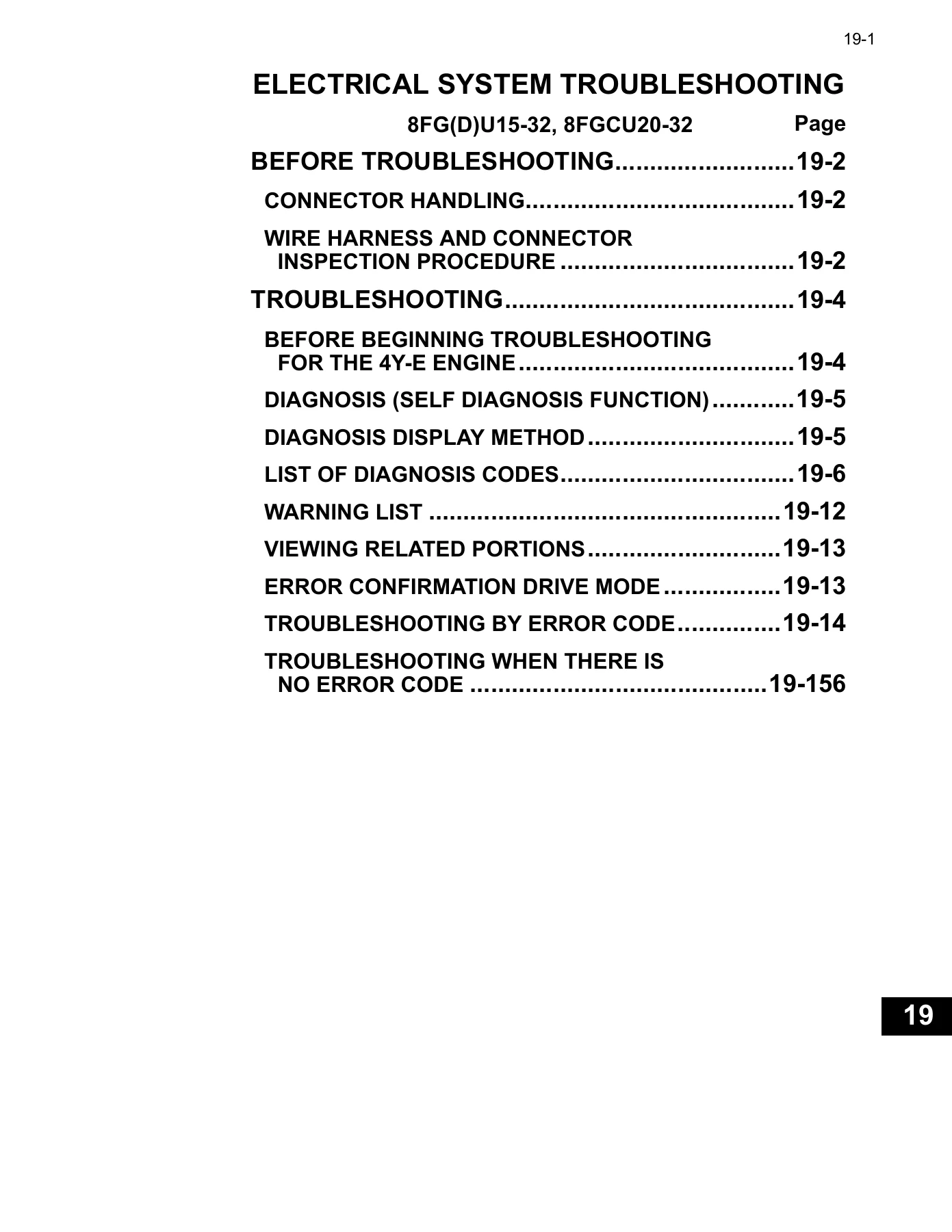
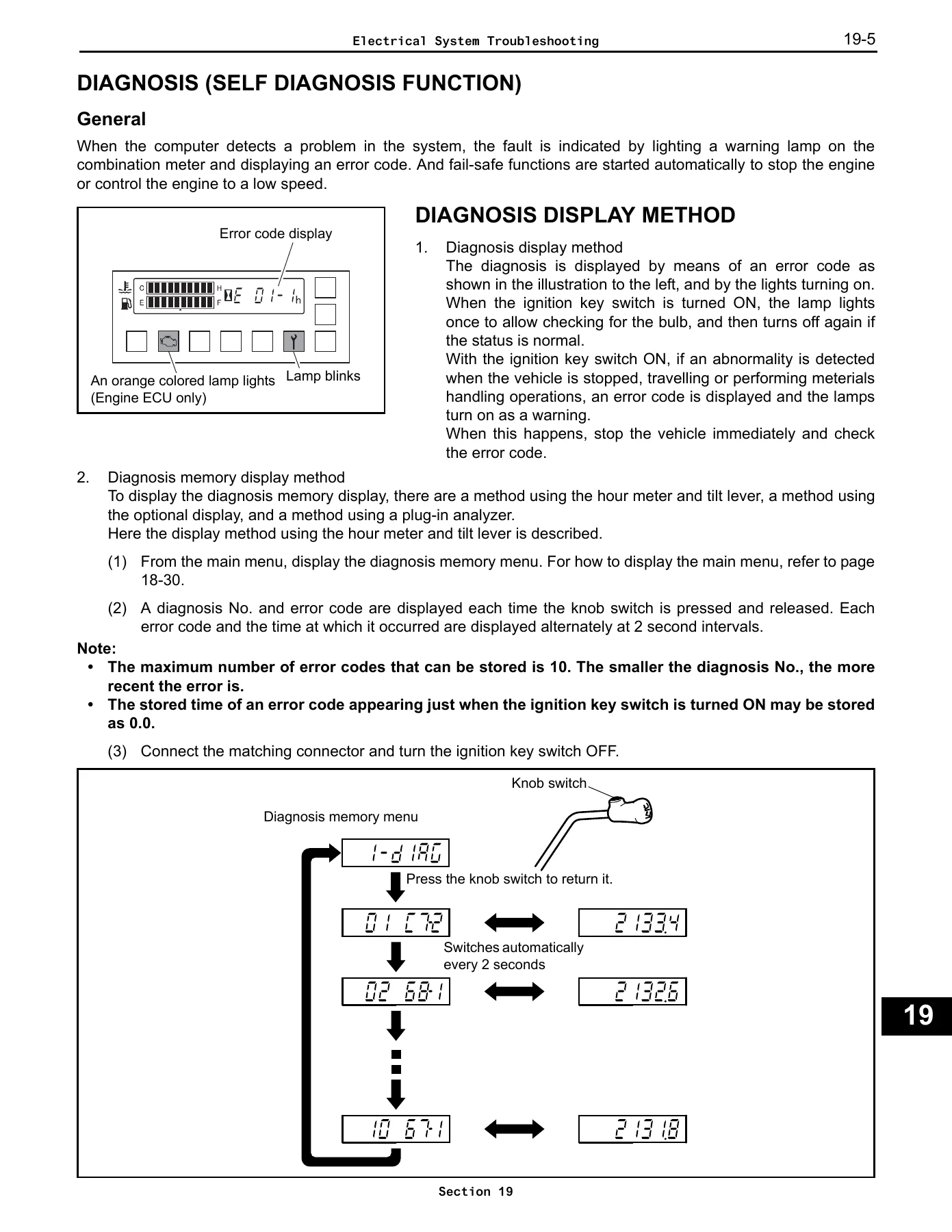
- Diagnosis (Self Diagnosis Function)
- Diagnosis Display Method
- List of Diagnosis Codes
- Warning List
- Error Confirmation Drive Mode
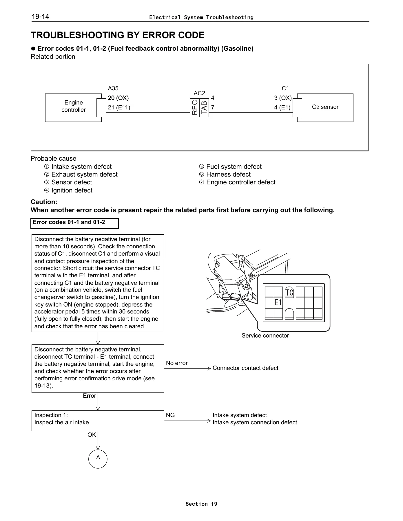
- Troubleshooting by Error Code
- Troubleshooting When There Is No Error Code
- Electrical Wiring Routings and Relay Locations
- System Circuits
- Ground Points
- Fuses for Power Supply
- Connector List
Electrical System Troubleshooting (Section 19)
This opening section establishes the correct sequence for approaching any electrical fault on the Toyota 8FG(D)U15-32 and 8FGCU20-32 forklifts. It opens with safety and handling rules for battery plugs, connector locking mechanisms, and tester probe contact. The wire harness and connector inspection procedure details continuity checks (10 Ω or less), insulation resistance checks (1 MΩ or above), and visual contact pressure checks. The self-diagnosis function section explains how the computer detects system problems, lights the warning lamp on the combination meter, and displays error codes while initiating fail-safe functions. The diagnosis display method covers both the hour meter and tilt lever approach and the optional display method. The list of diagnosis codes provides a complete table of error codes, detection ECU, spanner and wrench lamp behavior, and vehicle phenomenon for each code. The error confirmation drive mode gives a precise step-by-step procedure—warm up, fully depress the accelerator for 3 to 5 minutes, idle for 2 minutes, repeat three times, then cycle the ignition—to recreate fault conditions. Troubleshooting by error code walks through each code from 01-1 through HA-1 with related portion diagrams, probable causes, and inspection steps covering fuel feedback control, O2 sensor, intake temperature sensor, intake pipe negative pressure sensor, coolant temperature sensor, throttle position sensor, throttle motor circuits, electronic throttle, air-fuel ratio motor, low voltage, ignition signal, fuel specification determination, engine specification determination, speed sensor, yaw rate sensor, swing lock solenoid, load sensor, tilt angle sensor, tilt lever switch, lift lock solenoid, tilt control solenoid, lifting height switch, lift switch, backward tilt lock solenoid, tire angle sensor, steering angle sensor, knob position compensation solenoid, seat switch, brake switch, CAN communication, accelerator sensor, shift lever switch, forward-reverse travel lever, unload solenoid, and controller-to-combination-meter communication. The troubleshooting when there is no error code section provides a symptom-based list for the 4Y-E engine covering does not crank, cannot start, does not start well, idle problems, hesitation, after fire, and engine stalling.
Electrical Wiring Routings and Relay Locations (Section E2)
This chapter maps the physical installation positions of wire harnesses, ground points, connector numbers, and part names throughout the forklift. It covers the engine room for both 4Y-E and 1DZ engines, the instrument panel, front body, mast area, and rear body. Relay locations detail the junction block (J/B) and relay block (R/B) with internal circuit diagrams, connector codes, part numbers, and terminal numbers. The wire name symbols table decodes the alphabetical wire harness identifiers used throughout the diagrams.
System Circuits (Section E3)
This section presents the complete power source circuit and individual system circuit diagrams. It covers charging, starting, fuel, engine control (4Y-E), glow, ASC, LPG warning system, power shift transmission, EZ pedal, wet brake, SAS/OPS system, mini lever, diagnosis, rear working lamp, compartment lamp, strobe light, combination meter, multi display, front and rear wiper and washer, horn with rear horn switch, CNG digital meter, head lamp, turn signal lamp, clearance lamp, back up lamp buzzer and smart alarm, stop lamp, heater, fan, CAN communication, and earth-to-earth connections. Each circuit diagram shows the power source, fuse, relay, switch, component, ground point, wire color, terminal numbers, and connector codes.
Ground Points, Fuses, and Connector List (Sections E4, E5, E6)
The ground points chapter lists each ground code, its location, and the systems that use it. The fuses for power supply chapter breaks down the fusible link block assembly, fusible link block-1 and block-2, and the engine room relay block, showing each fuse rating, system name, and reference page. The connector list provides the shape, terminal number, color, and part number for every connector used in the electrical wiring routings and diagrams, including parts connectors and wire-to-wire connectors.
Why This Manual Matters
Electrical faults on Toyota forklifts can be among the most time-consuming and frustrating problems to diagnose without the right documentation. This manual gives you the exact error code definitions, the related portion wiring diagrams, the connector pinouts, the voltage and resistance standards, and the step-by-step inspection sequences that Toyota technicians use. Whether you are tracking down an intermittent fault in the SAS/OPS system, diagnosing a throttle motor circuit abnormality, checking the O2 sensor feedback control, or tracing a CAN communication error, this manual provides the precise procedures and specifications to get it right the first time. The wiring diagrams cover every circuit from the power source through the relays, fuses, switches, and ground points, so you can trace any wire from end to end. The diagnosis code tables cover all error codes from 01-1 through HA-1, with the exact vehicle phenomenon and the detection ECU for each. The error confirmation drive mode lets you recreate fault conditions under controlled conditions so you can verify the repair before returning the forklift to service.
IMAGES PREVIEW
Instant PDF Delivery
This Toyota 8FG(D)U15-32 and 8FGCU20-32 electrical troubleshooting and wiring manual is delivered as a high-quality PDF download immediately after payment. No shipping, no waiting, no physical media. The file works on any device—laptop, tablet, or smartphone—and every page is printable so you can take the diagrams and procedures directly to the machine. Whether you are a professional forklift technician, a fleet maintenance manager, or an owner-operator who prefers to handle electrical repairs yourself, this manual gives you the complete technical documentation you need to diagnose, repair, and verify electrical systems on these Toyota forklift models.
Reviews
There are no reviews yet.