
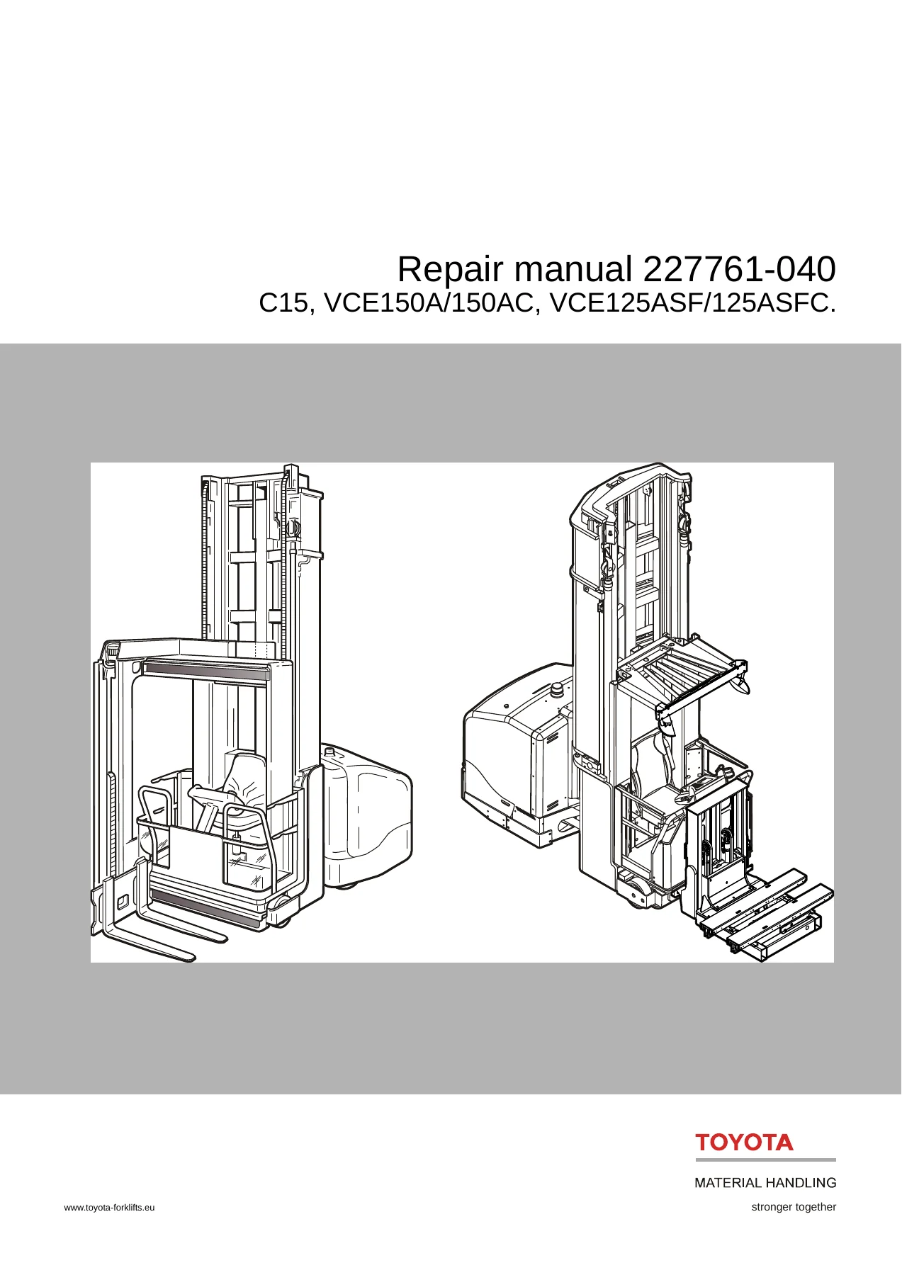
Toyota BT C15 VCE150A VCE150AC VCE125ASF VCE125ASFC Repair Manual 227761-040
Original price was: $39.95.$23.95Current price is: $23.95.
Complete Toyota BT repair manual for C15, VCE150A, VCE150AC, VCE125ASF and VCE125ASFC narrow aisle forklifts. Covers electric drive, hydraulic, braking, steering, wire guidance and mast systems across 700+ pages. Instant PDF download.
Description
File Details
- Manual type: Repair Manual
- Brand: Toyota / BT
- Models covered: C15, VCE150A, VCE150AC, VCE125ASF, VCE125ASFC
- T codes: 712, 713
- Publication number: 227761-040
- Document date: 2013-04-30 (completely reworked edition)
- Valid from serial number: 564221
- Language: English
- Page count: approximately 713 pages
- File format: PDF
Which Trucks This Toyota BT Repair Manual Covers
This Toyota BT C15 VCE150A VCE150AC VCE125ASF VCE125ASFC repair manual 227761-040 is the complete workshop-level service documentation for the BT narrow aisle reach truck family. It is split across two T codes that share most systems but differ in the fork unit design:
- T code 712 — C15 and VCE150A / VCE150AC with turret head fork unit
- T code 713 — VCE125ASF / VCE125ASFC with shuttle fork unit
Serial number coverage follows the factory grouping shown on the opening pages. Early build series and the later series from 6213314 (C15/VCE150A) and 6213314 (VCE125ASF) are both included, with the technical update appendix and revised wiring diagrams added for the later machines.
Chapters Covered
The manual is organised by BT C-codes, so you can jump straight to the system you are working on. The main sections are:
- General introduction — warning symbols, pictograms, repairability ratings
- P2 preventive maintenance — full maintenance schedule for C15/VCE150 (T code 712) and VCE125 (T code 713), plus frame crack inspection procedure
- P3 oil and grease specifications — lubricant types, ambient temperature ranges, viscosity classes and recommended products
- Tools – P4 — Super Seal contact tools, AMP connector tools, crimping, service instruments (CAN), TruckCom, drive gear puller, wheel axle tools, hydraulic pressure gauge, cabin lift remote control
- Chassis – 0000 — truck installation, unloading procedures (standing, lying down, crane), erecting, final assembly, commissioning, narrow aisle installation, support arm collision guards
- Frame pivot – 0320 — removal and reassembly of rear chassis, bearing frame links, upper bushing and dual conical roller bearing replacement
- General tightening torque – 0400 — galvanised non-oiled and untreated lubricated bolt torque tables, plus a master list of specific tightening torques
- Electric AC pump motor – 1710.1 — disassembly, assembly, ball bearing replacement, external temperature sensor
- Electric DC pump motor – 1710.2 — disassembly, installation, bearing replacement, carbon brushes, commutator truing
- Electric drive motor – 1760 — disassembly, gear wheel removal, brake disassembly/assembly, bearing replacement, temperature sensor
- Drive unit / gear – 2550 — component identification, technical data, oil level check and change, drive axle jointing ring, top and lower cover leaks, wheel bolts
- Brake system – 3100 — function description, parking brake, emergency braking, electro-mechanical disc brake on drive motor, multi-disc brake on support arms
- Wheels – 3500 — drive wheel, support arm wheels, wheel bearings, axles, available wheel grades
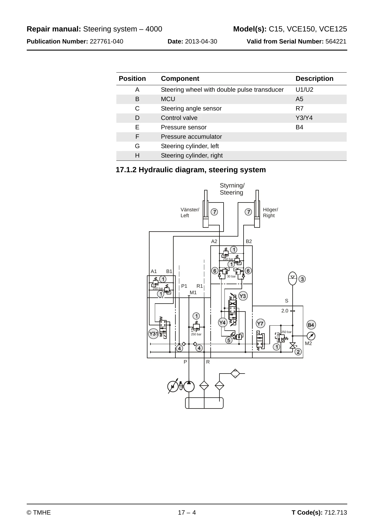
- Steering system – 4000 — components, hydraulic diagram, electrical system, rail-guided narrow aisle mode, temperature and voltage compensation, troubleshooting
- Steering cylinder – 4160 — internal leak checking, removal and installation
- Wire guidance system – 4500 — components, functional description, travel speeds, automatic steering control, adjustment best practice, parameters, warning and error codes
- Electrical system – 5000 — MCU (A5), FCU (A4), ICP (A16), AC regulators ACTL/ACTR/ACH, DC regulator DCHI, hand-held terminal 1307, symbol list, complete wiring diagrams for VCE150A and VCE125ASF, component list and locations
- Parameters – 5700 — operator parameters, MCU parameters, FCU parameters for turret head and shuttle fork units, ICP parameters, learned calibration values
- Calibration – 5700 — ICP controls, steering, wire guidance, turret head fork unit functions, shuttle fork, weight indication, B cylinder pressure
- Error codes – 5700 — full warning and error code descriptions grouped by ICP, MCU, drive system, cabin lift, steering, initial lift and fork unit systems
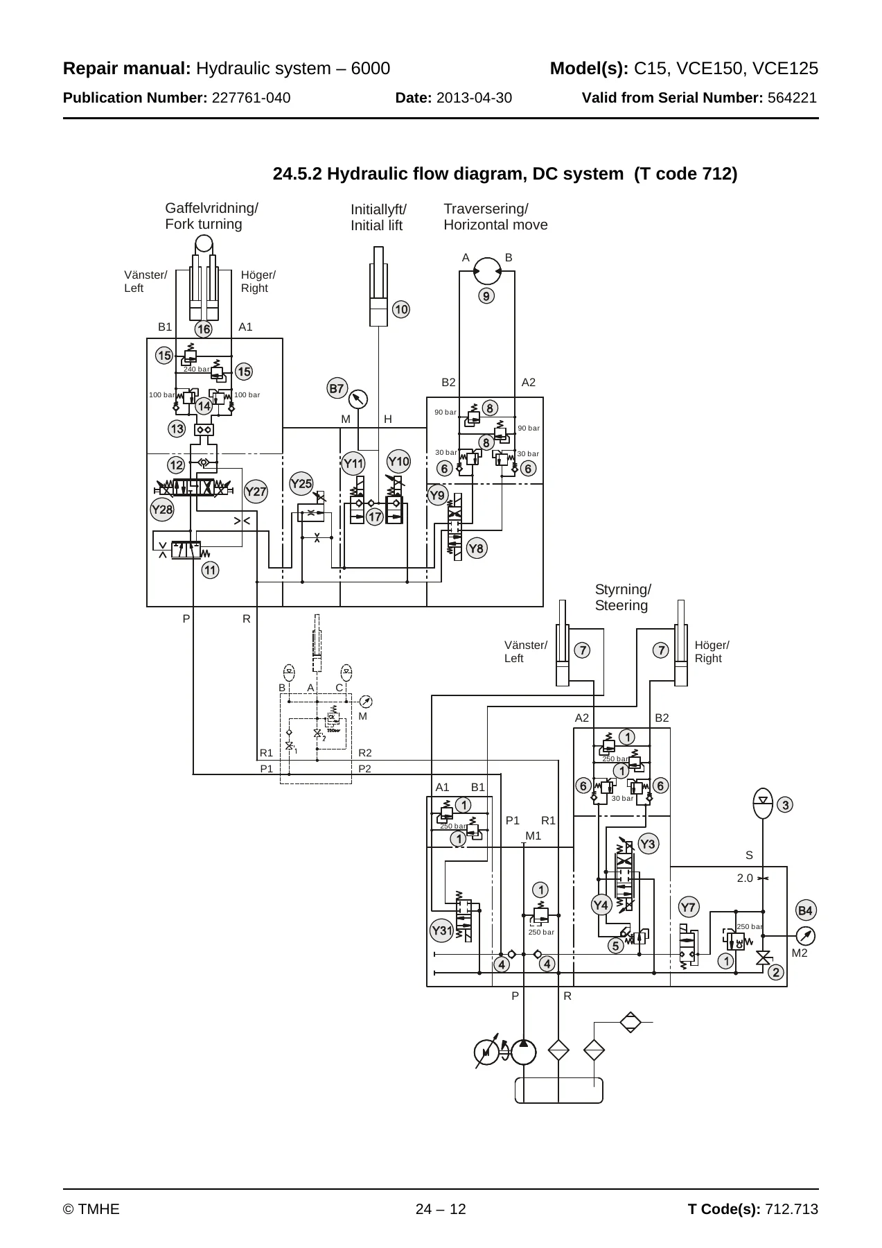
- Hydraulic system – 6000 — cleanliness procedures, symbols, cabin lifting, B cylinder system, fork units, steering, extra hydraulic functions, hoses and couplings, valve repair
- Hydraulic tank – 6110 — oil replacement, tank removal and installation
- Hydraulic pump – 6140 — bleeding procedures, main lift pump replacement, steering and fork hydraulic pump replacement, internal leak troubleshooting
- Accumulators – 6280 — charging and pressure testing of lifting and steering accumulators, country-specific adapter kits
- Main lift cylinder – 6610 — B cylinder seal replacement
- Main mast and mast – 7100 — setting cab and mast stoppers
- Main lift chain system – 7120 — chain checking (noise, rust, stiff links, bolt rotation, outline wear, stretching), cleaning, lubrication, adjustment of main lift, cabin and initial mast chains
- Initial mast / Turret head fork unit – 7200 (T code 712) — assembly, disassembly, belt installation, belt inspection and replacement, belt tensioning, friction plate adjustment, fork parallelism
- Shuttle fork – 7800 (T code 713) — assembly, maintenance schedule, lubrication, chain adjustment, shuttle fork replacement
- Magnet installation in narrow aisle – 8100 — magnetic sensor switch positions, aisle end brake magnet positions
- Wire guidance equipment – 8200 — generator technical data
- Height preselection – 9390 — MCU parameters, programming levels, automatic operations
- Appendix A: Technical update — new AC pump motor, new AC drive motors, generation 5 motor controllers, new pivot point/steering potentiometer, updated wiring diagrams from serial number 6213314
Taken as a whole, this Toyota BT repair manual gives a technician the complete factory workflow for these trucks — from unloading and commissioning through to component-level overhaul, electrical diagnostics, hydraulic repair, calibration and error code troubleshooting. Every procedure is written as a sequence of steps with torque values, special tools, safety warnings and calibration references built in.
Systems and Repairs Covered in Detail
The electrical section alone spans hundreds of pages and includes the main computer unit, fork computer unit, integrated control panel and the frequency converters that drive the two AC traction motors and the AC lift pump motor, plus the DC controller for the initial lift pump. Full connector pinouts are given for X130, X131 and X132 on the MCU, X100 through X107 on the ICP, and the FCU connector. Complete wiring diagrams are provided for both VCE150A (T code 712) and VCE125ASF (T code 713) from serial number 6213314.
On the hydraulic side, the manual separates the cabin lift system (AC pump, accumulators, B cylinder) from the steering and fork hydraulic system (DC pump, steering accumulator, proportional and routing valves). Valve sections are shown with tightening torques, and the routing valves with replaceable inserts are broken down into disassembly and installation steps.
Chassis and driveline work is covered end to end: rear chassis removal with bearing replacement, drive unit removal from the chassis, drive motor and gear separation, wheel and bearing replacement, and the multi-disc support arm brakes with play adjustment and inspection limits.
Why This Toyota BT Repair Manual Matters
These trucks are complex machines. The steering, wire guidance, height preselection and load handling systems all run through electronic controllers that must be calibrated after any major repair. Getting a value wrong — an air gap, a valve current, a potentiometer voltage, a chain adjustment — can cause the truck to lose the wire, drop out of aisle mode, or fail a safety check. This manual gives you the factory specifications, the calibration sequences and the error code definitions you need to do the job correctly the first time.
The error code section covers groups 1 through 6 with warning and error codes for the ICP, MCU, drive system, cabin lift system, steering system and the initial lift / fork unit systems. Each code has a description, probable cause and a suggested procedure. That alone can save hours of guesswork.
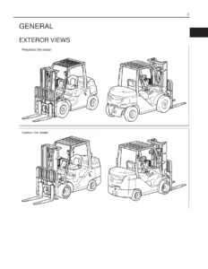
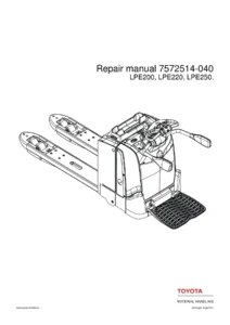
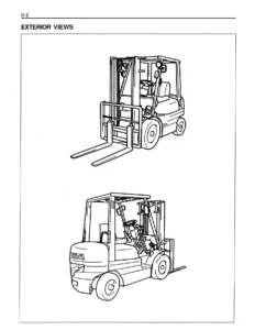
IMAGES PREVIEW
Instant PDF Delivery
This is a digital download. After payment you receive the Toyota BT C15 VCE150A VCE150AC VCE125ASF VCE125ASFC repair manual 227761-040 as a PDF file, ready to open on a laptop, tablet or phone. No shipping, no waiting, no physical book to lose in the workshop. Print the pages you need for the job at hand, or keep the whole manual on a device and search through it as you work. Whether you are servicing one truck or running a fleet, this is the reference that belongs on the shelf.
Reviews
There are no reviews yet.