
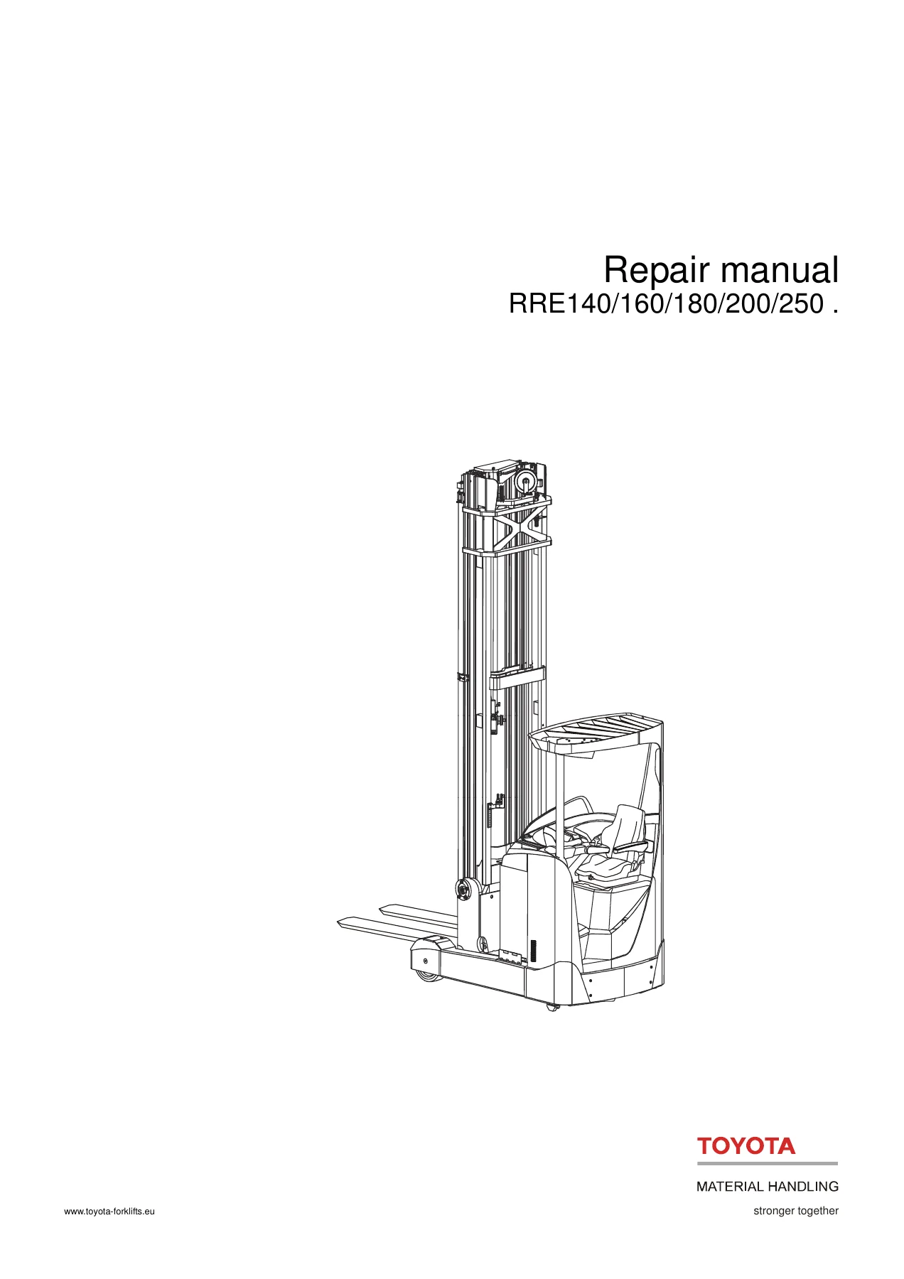
Toyota BT RRE140 RRE160 RRE180 RRE200 RRE250 Reach Truck Repair Manual 7510399-040
Original price was: $44.95.$26.95Current price is: $26.95.
942-page Toyota Material Handling repair manual for RRE140, RRE160, RRE180, RRE200 and RRE250 reach trucks from serial number 6070557-. Covers maintenance, troubleshooting, parameters, calibration, electrical systems, hydraulics, brakes, steering, mast and lift repairs, wiring diagrams, hydraulic schematics, service data and technical data.
Description
Toyota BT RRE140 RRE160 RRE180 RRE200 RRE250 Reach Truck Repair Manual 7510399-040
This Toyota BT RRE140 RRE160 RRE180 RRE200 RRE250 Reach Truck Repair Manual 7510399-040 is a detailed service reference for the RRE reach-truck range covered by T-Codes 815 and 816. The manual applies from serial number 6070557- and combines system descriptions with maintenance, troubleshooting, adjustment, calibration, removal, installation and repair procedures. Its coverage extends well beyond routine servicing into drive, braking, steering, electrical, hydraulic, mast and lift-system work, with dedicated wiring and hydraulic schematic sections for fault tracing.
File Details
- Manual type: Repair manual
- Brand: Toyota Material Handling
- Models: RRE140 / RRE160 / RRE180 / RRE200 / RRE250
- Language: English
- Pages: 942
- File format: PDF
- Publication number: 7510399-040
- Date: 2016-10-24
- T-Codes: 815, 816
- Applies from serial number: 6070557-
Model and System Coverage
The repair information is organized around the complete truck rather than a single component group. The manual identifies RRE140 and RRE160 variants under T-Code 815 and RRE180, RRE200 and RRE250 variants under T-Code 816. Within the technical chapters it explains the operating relationships between the Central Information Display, Main Control Unit, traction and lift regulators, steering servo, sensors and CAN communication, giving technicians the background needed before moving into parameter setting or diagnosis.
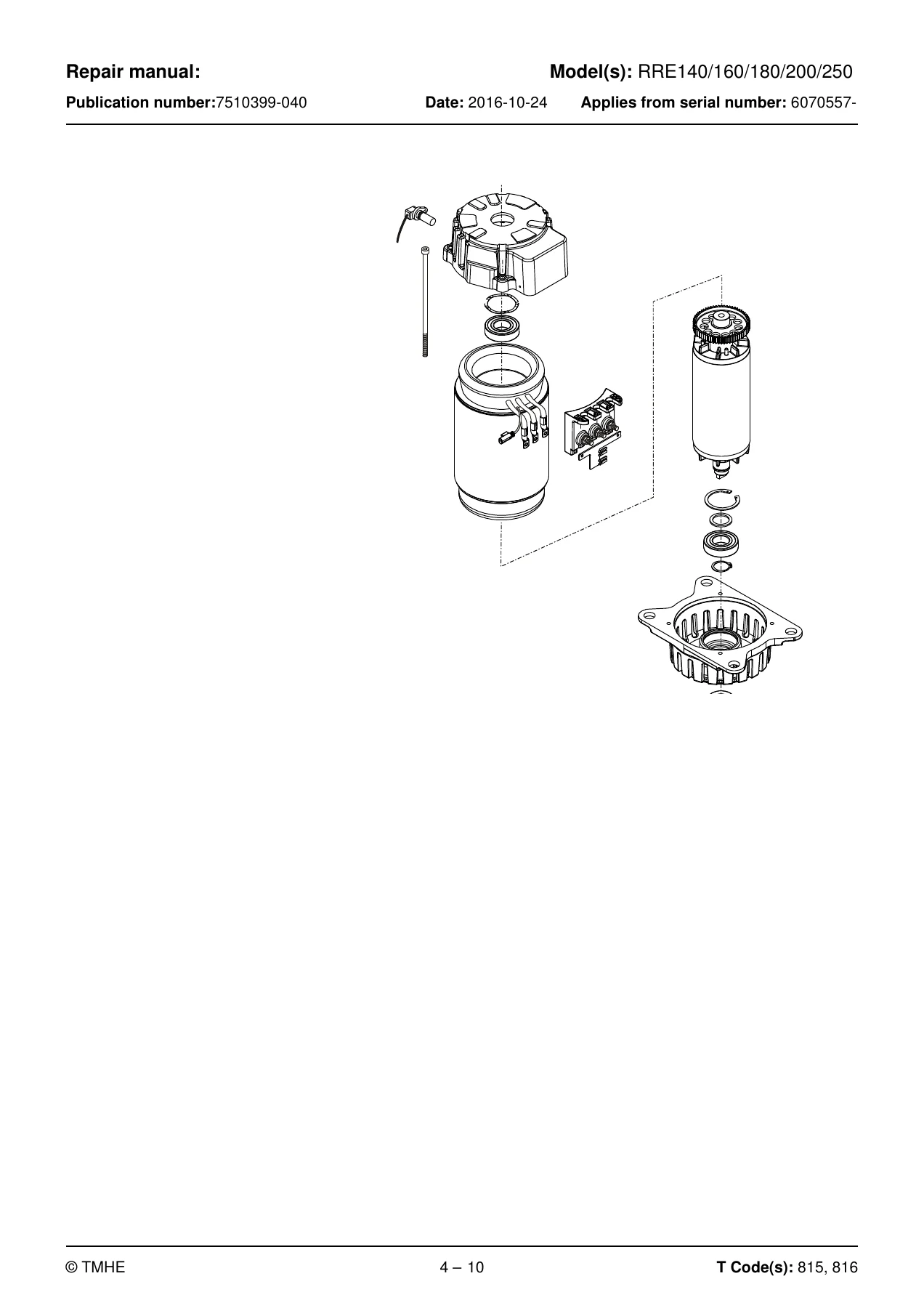
Electric drive, pump and steering systems receive substantial coverage. The manual identifies 48 V motor systems, describes the drive and pump motors as three-phase AC units, explains the steering motor and its control, and follows these descriptions with repair procedures for bearings, sensors, cooling fans and drive-motor removal, dismantling, assembly and refitting. The drive gear chapter covers oil level checks, oil change, leakage and drive-gear replacement, while the brake chapters deal with regenerative braking, support-arm brake arrangements, the parking brake, brake-force checks, wheel work and wheel-bearing service.
Diagnostics, Parameters and Calibration
A major portion of this Toyota BT RRE140-250 repair manual is devoted to electronic setup and troubleshooting. Operator, service, factory and calibration parameters are described in dedicated sections. The manual shows how truck behavior can be configured for steering response, travel functions, hydraulics, display functions, optional equipment and calibration. It also documents CID service functions for pressure relief, cylinder bleeding, fan testing, valve calibration, hydraulic-control calibration, weight calibration and sensor calibration.
Troubleshooting material includes error-log and error-information menus, diagnostic screens, initial fault checks, blocking-symbol diagnosis and error-code based procedures. Separate fault groups address CID and MCU warnings, drive-system errors, hydraulic-system errors, steering warnings and errors, external systems and faults that occur without a display indication. This makes the manual useful for both symptom-led diagnosis and code-led electrical or hydraulic troubleshooting.
Hydraulic, Mast and Lift Repairs
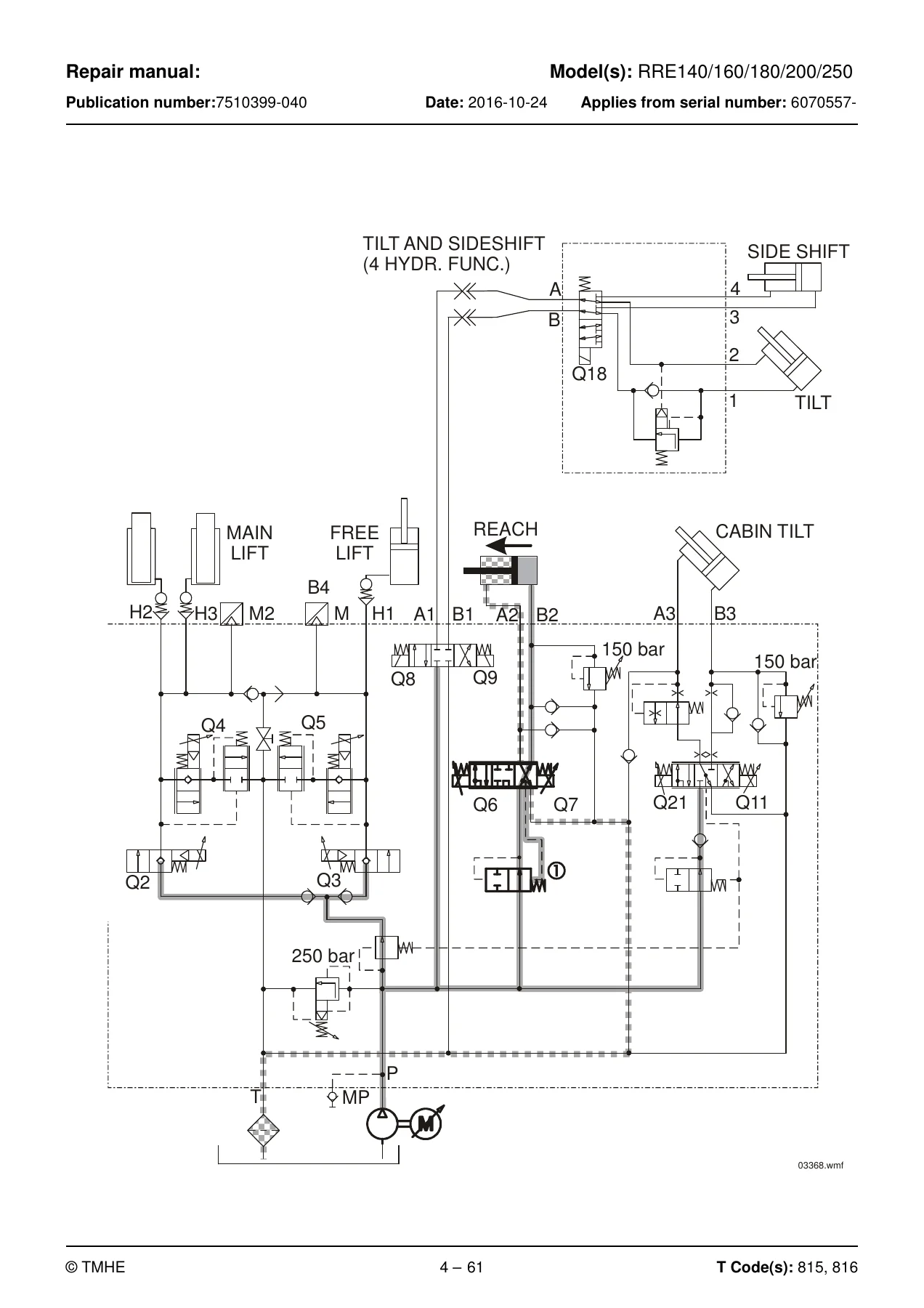
The hydraulic sections explain the tank, return filtration, gear-type pump, main valve block, pressure limitation, lift and lowering circuits, reach movement and auxiliary functions. The hydraulic tank is specified at approximately 25 litres, with a 10 micrometre return-filter element. The main system pressure limiter is described at 25 MPa (250 bar), while pressure-reducing valves for reach movement and applicable cabin tilt are given as 15 MPa (150 bar). Detailed service procedures then cover the hydraulic unit, pump, main valve, connections, hose reels and cylinder work.
Cylinder procedures include the main lift cylinder, free lift cylinder, reach cylinder, fork tilt cylinder, cab tilt cylinder and sideshift cylinder. Depending on the assembly, the manual takes the technician through removal, dismantling, piston and cylinder-head work, seal installation, reassembly and refitting. The mast and lift-system chapter continues with chain inspection and lubrication, mast removal and installation, mast-clearance adjustment, damper plates, free-lift chain work, reach-carriage adjustment, fork inspection and repair, fork carriage, fork spread, fork extensions and manual or hydraulic shuttle forks.
Chapters Covered
- 2 – General introduction: using the manual, warning symbols and pictograms.
- 3 – General safety rules: work safety, electrical-system precautions and safe lifting.
- 4 – Descriptions of functions: chassis, motors, drive gear, brakes, steering, operation area, sensors, operating sequences, control functions, height preselector, hydraulics, mast, lifting devices and accessories.
- 5 – Parameters: operator parameters, general service parameters, travel-function parameters, hydraulic parameters, CID parameters, factory parameters, option activation and calibration parameters.
- 6 – Installation: truck and mast transport, commissioning, battery and mast fitting, initial-operation parameters and optional-equipment parameters.
- 7 – Maintenance: safety, cleaning, crack inspection and periodic maintenance at 500, 1000, 2000, 3000 and 5000 operating hours, plus annual status inspection.
- 8 – Troubleshooting: error log, error information, diagnostic screens, initial troubleshooting, blocking symbols, error codes and system-specific fault diagnosis.
- 9 – Frame/Chassis 0000: motor hood, battery compartment, operator cabin, windows, doors, seat and operator compartment, pedals, overhead guard and safety equipment.
- 10 – Motors 1000: motor sensors, pump motor, steering motor and steering unit, cooling fans and drive motor.
- 11 – Drive gear 2000: serviceability, oil level, oil change, leakage and drive-gear replacement.
- 12 – Brake and wheel 3000: travel brakes, support-arm brakes, parking brake, drive wheel, wheel studs, support-arm wheels and bearings.
- 13 – Steering system 4000: steering wheel module, pulse transducer, steering console, reference sensor and steering bearings.
- 14 – Electrical system 5000: battery installation, lithium-ion battery replacement, LID, pedals, control console, sensors, parameter settings, PIN menu, calibrations, wiring harness and MCU.
- 15 – Hydraulic system 6000: hydraulic hygiene, pump and tank work, main valve, hydraulic connections, hose reels and lift, reach, tilt and sideshift cylinders.
- 16 – Mast/Lift system 7000: chain checks, lubrication and adjustment, mast replacement, mast clearance, lift chains, reach carriage, forks, fork carriage, fork spread and shuttle forks.
- 17 – Peripherals 8000: peripheral-system section.
- 18 – Optional equipment 9000: Smart Access 2 and Pre-Op Check.
- 19 – Destruction instructions: plastics marking, pressure vessels and sorting categories.
- 20 – Wiring diagram: components, component locations, cable connections, terminal posts, fuse box, system overview and detailed diagrams.
- 21 – Hydraulics schematics: main valve unit, schematic designations, symbols and RRE/RRE Ergo hydraulic diagrams.
- 22 – Tools: AMP connectors, MQS connectors, CPC contacts and other tools.
- 23 – Service data and grease specifications: general tightening torques and lubricant specifications.
- 24 – Technical data: technical-data reference section.
Taken together, these chapters provide a connected view of how the RRE truck operates and how its systems are serviced. Function descriptions explain what should happen; parameter and calibration sections show how control behavior is set; diagnostic chapters help locate faults; and the repair chapters supply the mechanical, electrical and hydraulic procedures needed to correct them. Wiring diagrams, hydraulic schematics, torque information, lubricant data and technical data remain available as reference material while carrying out the work.
Electrical and Hydraulic Diagrams for Fault Tracing
The dedicated wiring section is particularly useful when a repair moves beyond component replacement into circuit diagnosis. Component lists and locations, cable connections, terminal posts, fuse information and detailed diagrams support tracing between controls, sensors, displays, the MCU, traction and hydraulic regulators and other electrical equipment. The separate hydraulics schematic chapter shows the main valve arrangement and hydraulic circuits for RRE and RRE Ergo configurations, helping relate valve designations and pressure paths to the operating descriptions and service procedures elsewhere in the manual.
Repair and Service Reference in One PDF
IMAGES PREVIEW
The Toyota BT RRE140 RRE160 RRE180 RRE200 RRE250 Reach Truck Repair Manual 7510399-040 supports scheduled maintenance, troubleshooting, calibration, electrical diagnosis, hydraulic fault tracing and major component repair on the covered trucks. Having the correct procedures, parameter information, diagrams, tightening information and service data together helps technicians work systematically instead of relying on trial and error. Delivery is an instant PDF download after payment, with no shipping required; the file can be opened on compatible phones, tablets and computers and printed when a paper workshop reference is preferred.
Reviews
There are no reviews yet.