
Toyota 8FG35N-80N 8FD35N-80N Forklift Repair Manual
Original price was: $44.95.$26.95Current price is: $26.95.
Comprehensive workshop repair manual covering the Toyota 8FG35N-80N and 8FD35N-80N series internal combustion forklifts (3.5 to 8.0 ton capacity). Features complete technical specifications, disassembly and assembly instructions, hydraulic schematics, torque converter overhaul, and troubleshooting procedures for 1FS gasoline/LPG and 1KD diesel models.
Description
Complete Workshop Service & Repair Documentation for Toyota 8-Series Forklifts
This technical publication serves as the complete Toyota 8FG35N-80N 8FD35N-80N Forklift Repair Manual, engineered specifically for maintenance professionals, service technicians, and fleet managers responsible for servicing and overhauling heavy-capacity Toyota internal combustion counterbalanced forklifts. Providing thorough coverage for the entire heavy-duty model range from 3.5-ton to 8.0-ton trucks, this service manual supplies the step-by-step procedures, mechanical clearances, wear tolerances, tightening torque sequences, and hydraulic operating parameters required to restore equipment to precise original performance standards.
File Details
- Document Type: Workshop Service & Repair Manual
- Brand: Toyota
- Model Series: 8FG35N, 8FG40N, 8FG45N, 8FG50N, 40-8FD35N, 40-8FD40N, 40-8FD45N, 40-8FD50N, 40-8FD60N, 40-8FD70N, 40-8FD80N
- Engine Applications: Toyota 1FS (Gasoline / LPG / Convertible) and Toyota 1KD (Common Rail Turbo Diesel)
- Language: English
- Page Count: 593+ pages
- Format: Digital PDF (High-clarity technical diagrams, vector line drawings, and tables)
Comprehensive Engineering Coverage: Toyota 1FS & 1KD Powertrains
The Toyota 8FG35N-80N 8FD35N-80N Forklift Repair Manual delivers exhaustive mechanical overhaul and diagnostic procedures for both powerplants utilized across the heavy pneumatic forklift lineup. Technicians working on Toyota 8FG35N-80N machines will find complete service sequences for the 3.7-liter inline-4 1FS engine in pure gasoline, dedicated LPG, and convertible dual-fuel configurations. The manual details Electronic Throttle Body (ETB) calibration, fuel injector bench flow rates (78 to 82 cc per 15 seconds), delivery pipe union bolt fuel pressure relief, LPG primary and secondary chamber pressure regulations (24.5 to 34.3 kPa), heated oxygen sensor (O2) and VF voltage trimming (2.5 ± 1.25 V at idle), electronic governor resistance limits, and ignition system continuity tests.
For heavy-duty diesel applications, the manual contains in-depth procedures for the 3.0-liter common-rail turbocharged 1KD engine powering the Toyota 8FD35N-80N models. Coverage includes ultra-low sulfur diesel fuel specification requirements (EN590: 2013), supply pump suction control valve resistance tests (1.9 to 2.3 Ω at 20°C), common rail fuel rail pressure evaluation (30,000 to 40,000 kPa at warm idle), pre-heating system and glow plug resistance verification (0.7 Ω at 20°C), electronic EGR control valve cleaning and gap tolerance testing, air flow meter data monitor readings, variable nozzle turbocharger actuator resistance checks, fuel filter sedimenter warning reset sequences, and manual priming pump air bleeding instructions.
Torque Converter, Transmission, Axles, and Running Gear
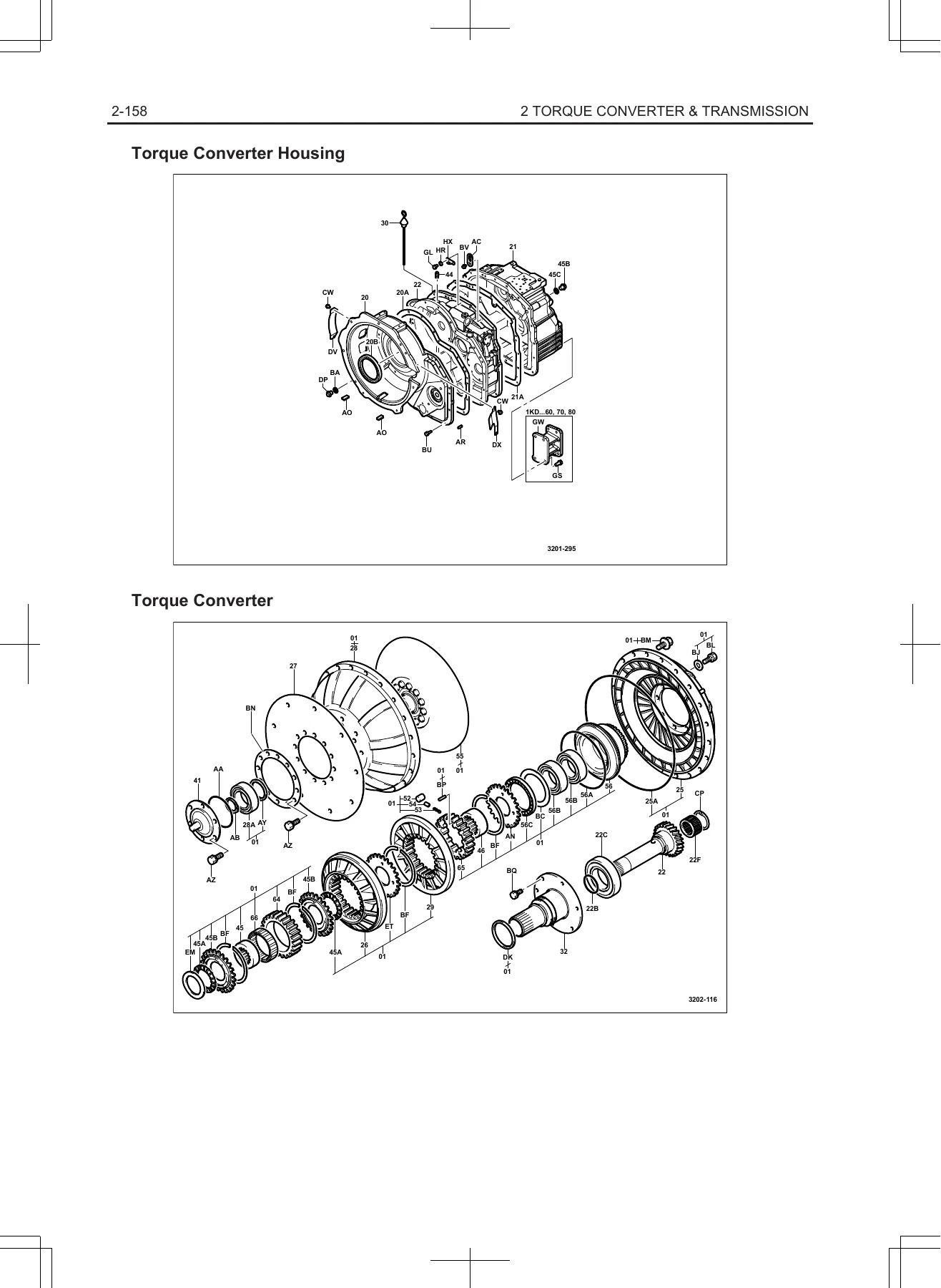
Detailed chapters guide the rebuilder through the multi-stage Okamura torque converter and powershift transmission assembly. The Toyota 8FG35N-80N 8FD35N-80N Forklift Repair Manual presents exact teardown paths for the 4-member, 2-stage, 3-phase torque converter with a 5.1 stall-to-torque ratio, detailing pump impeller hub runout, turbine runner spacer selection formulas (A − [B + C + thickness] = 0.2 to 0.8 mm), stator one-way clutch orientation, and oil pump drive gear bush clearances. Full diagnostic instructions outline main hydraulic line pressure testing (900 to 1300 kPa at 2000 rpm), forward/reverse wet multi-disc clutch pack piston stroke and return spring limits, inching spool travel, and complete stall rotational speed tests (1750 rpm for both 1FS and 1KD models).
Driveline and running gear coverage extends from universal joint propeller shaft balancing through full-floating banjo-type front drive axles and planetary reduction final drives (3.00 ratio on 3.5–5.0 ton models; 4.25 ratio on 6.0–8.0 ton models). Step-by-step instructions detail drive pinion preload setting via precision shims, ring gear tooth contact patterns, hypoid gear backlash adjustment (0.2 to 0.3 mm), front axle hub bearing preload using spring scale starting force measurements (72 to 160 N on 3.5–5.0 ton; 88.2 to 156 N on 6.0–8.0 ton), and Elliot-type center-supported rear steer axle king pin needle bearing press-fitting depths.
Hydrostatic Steering, Duo-Servo Brakes, and Hydraulic Mast Assemblies
Hydraulic service sections comprehensively address Nishina and Sauer Danfoss power steering valves, priority flow divider circuits, and knob position correction solenoid valves for synchronized steering options. Mechanical service instructions outline duo-servo internal expanding hydraulic front brakes, master cylinder and hydraulic brake booster power piston overhaul, automatic brake shoe adjuster operation, parking brake lever pull force calibration, and single/dual brake-inching pedal linkages.
Extensive coverage is dedicated to the material handling system across standard V (two-stage limited free lift), FV (two-stage full free lift), and FSV (three-stage full free lift) masts. Clear instructions specify lift cylinder piston seal replacement, natural drop testing (45 mm / 15 min limit), natural forward tilt drift checking (25 mm / 15 min limit), inner-to-outer mast lift roller shim distribution (0 to 0.8 mm clearance), lift bracket side roller alignment, chain link pitch elongation wear gauge limits, and cylinder rod shimming to eliminate uneven lifting motion between cylinders.
Chapters Covered
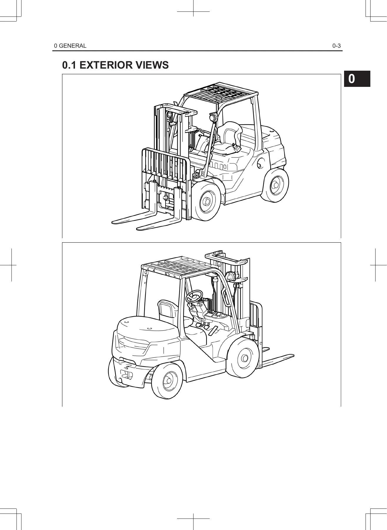
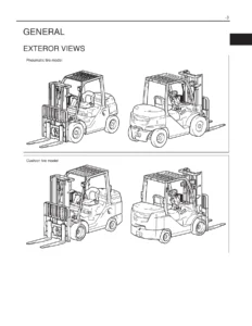
- 0 GENERAL: Exterior Views; Vehicle Model Classifications; Frame Number Stamping Locations; How to Use This Manual & Component Figures; Operational & Jacking Safety Tips; Hour Meter Connector Activation; 1KD Timing Belt Warning Reset; Periodic Maintenance Schedule (250h, 500h, 1000h, 2000h); Frame Bolt Precautions; Circuit Tester Measurements; Standard Bolt & Nut Tightening Torques; Precoat Thread Sealant Procedures; High-Pressure Hose Fitting Tightening Torques; Vehicle Hoisting & Slinging Angles; Component Service Weights; Recommended Lubricants & Fluid Capacities; Chassis Lubrication Chart; Periodic Parts Replacement Intervals.
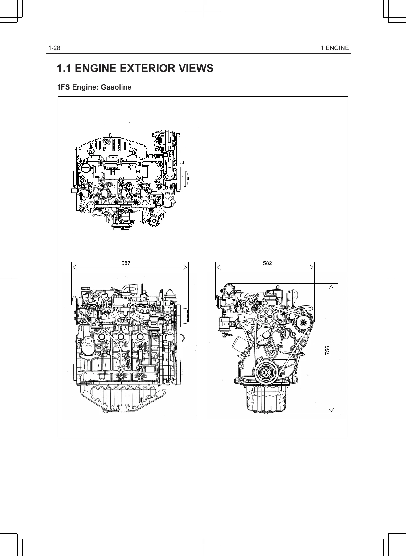
- 1 ENGINE: 1FS Gasoline/LPG & 1KD Diesel Exterior Views; Major Engine Specifications & Performance Curves; Complete Engine Removal & Installation Steps; Common Rail Diesel Fuel Air Bleeding; Multifunction Display & SST Plug-In Analyzer Diagnostic Tests; 1FS Engine Inspection, Idle/Relief RPM, Cylinder Compression Testing (1550 kPa standard), V-Belt Adjustment, Oil Pressure Test, Distributorless Ignition Diagnostics, LPG Vaporizer & Solenoid Inspection, Fuel Pump & Injector Testing, Electronic Throttle Cleaning; 1KD Diesel Inspection, Idle/NMR Speed, Compression Measurement (2.5 MPa standard), Glow Plug System, Rail Pressure, Sensor Diagnostics, Variable Turbocharger, Common Rail, Electric EGR Valve, EN590 Diesel Fuel Parameters; Cyclone Air Cleaner Service; Radiator & Cooling System Capacities; Fan Drive Assembly & Tensioning; Fan Drive Propeller Shaft Overhaul; Muffler, Catalytic Converter & Exhaust Piping; LPG Regulator Inspection & Overhaul; LPG Solenoid & Filter; 1FS In-Tank Fuel Pump & Sender; 1KD Fuel Filter & Water Sedimenter; Starter Motor; Battery Specific Gravity; Accelerator Pedal Sensor Calibration; Optional EZ Reversing Pedal Linkage.
- 2 TORQUE CONVERTER & TRANSMISSION: General Layout & Operational Flow; Complete Hydraulic Circuit Diagrams; Technical Specifications & Gear Ratios; Disassembly & Component Breakdown; Step-by-Step Mechanical Troubleshooting Charts; Torque Converter Disassembly, Stator One-Way Clutch, Turbine Runner End Play & Bearing Replacement; Transmission & Converter Removal/Installation; Transmission Case Disassembly & Reassembly; Stator Shaft No. 2 & Internal Gear Oil Pump Service; Forward & Reverse Wet Multi-Disc Clutch Drum Overhaul; Direction Selector Switch Pinout & Continuity; Hydraulic Line Pressure Testing & Converter Stall Speed Tests.
- 3 PROPELLER SHAFT: Drive Joint Layout & Centerline Dimensions; Joint Specifications; Exploded Component Views; Propeller Shaft Removal, Flange Disconnection & Installation; Universal Joint Spider & Needle Bearing Overhaul; Cross-Type Spider Disassembly & Reassembly.
- 4 DIFFERENTIAL: Banjo-Type Differential Carrier Overview; Drive Pinion & Ring Gear Reduction Specifications; Exploded Assembly Views; Differential Assembly Removal & Installation for 3.5–5.0 Ton and 6.0–8.0 Ton Trucks; Drive Pinion Bearing Preload Adjustment; Ring Gear Backlash Adjustment & Tooth Contact Marking; Differential Case Teardown, Spider Pin, Pinion Gear & Side Gear Thrust Washer Replacement.
- 5 FRONT AXLE: Full-Floating Drive Axle Architecture; Wheel & Tire Specifications (Pneumatic & Dual Rim Inflation Limits); Front Axle Assembly Removal & Installation (3.5–5.0 Ton); Front Axle Assembly Removal & Installation (6.0–8.0 Ton); Wheel Hub & Planetary Reduction Final Drive Overhaul; Axle Shaft Removal; Planetary Bushing Replacement; Hub Bearing Lock Nut Preload & Starting Force Adjustment.
- 6 REAR AXLE: Elliot-Type Rocking Steer Axle Architecture; SAS Swing Lock Cylinder Mounting; Axle Alignment & Steering Geometry Specifications; Exploded Views (Standard & SAS Dual Wheel Models); Steer Tire Inflation Standards; Complete Rear Axle Assembly Removal & Center Pin Bushing Service; Rear Axle Hub & Knuckle Disassembly, King Pin Needle Bearing Press-Fitting & Preload Shimming; Double-Acting Hydraulic Steer Cylinder Overhaul & Piston Seal Replacement.
- 7 STEERING: Tilt & Optional Telescopic Column Mechanisms; Hydraulic Circuit Diagram; Hydrostatic Steering Valve Technical Specifications; Column & Mast Jacket Removal & Disassembly; Nishina & Sauer Danfoss Orbitrol Steering Valve Overhaul, Metering Gerotor Gear Set, Centering Leaf Springs & Spool Alignment; Power Steering Relief Pressure Testing & Setting; Synchronized Steering Knob Correction Solenoid Valve Service.
- 8 BRAKE: Hydraulic Brake System Schematic; Duo-Servo Front Drum Brake Assembly; Master Cylinder & Hydraulic Booster Cross-Section; Mechanical Parking Brake Linkage; Technical Specifications & Lining Wear Limits; Front Brake Shoe Disassembly, Inspection & Reassembly; Brake Line Air Bleeding; Stopping Distance Road Testing; Hydraulic Brake Booster Overhaul & Reaction Piston Seal Service; Parking Brake Lever Pull-Force Adjustment; Service Brake & Inching Pedal Linkage Adjustments.
- 9 BODY: Frame Body Components & Fasteners; Radiator Cover & Fender Panels; Counterweight Hoisting & Bolt Torquing (520 to 700 Nm); Engine Hood Damper Removal; Driver Seat Switch Safety Continuity Tests; Retractable Seatbelt Locking Inspection; Halogen Headlamp Bulb Servicing; Multifunction Combination Meter Removal; Steering Column Combination Light & Turn Signal Switch Continuity.
- 10 MATERIAL HANDLING SYSTEM: Complete Machine Hydraulic Circuit Schematics (Cowl & Mini-Lever Options); Suction Strainer & Return Oil Filter Replacement; Mast Natural Drop Test (15-Minute Limit); Natural Forward Tilt Hydraulic Drift Test; Lift Cylinder Internal Leakage Measuring; Tilt Cylinder Internal Leakage & Tilt Lock Valve Verification.
- 11 MAST: V, FV, and FSV Mast Structural Layouts; Mast Assembly Removal with and without Lift Bracket; Lift Cylinder Removal & Strip Inspection; Inner and Outer Mast Channel Overlap & Roller Clearance Shimming; Lift Bracket Roller & Side Thrust Roller Adjustment; BL-Series Leaf Chain Elongation Inspection & Stud Bolt Torquing; Fork Tine Misalignment Checking; FV & FSV Mast Multi-Stage Channel Alignment; Lift Cylinder Rod End Shimming for Synchronized Stroke.
- 12 CYLINDER: Structural Breakdowns, Disassembly, Rod Inspection, and Seal/Packing Replacement Procedures for Lift Cylinders and Tilt Cylinders.
- 13 OIL PUMP: Engine-Driven Main Hydraulic Gear Pump Removal, Inspection, Wear Clearances, Flow Characteristics, and Installation.
- 14 OIL CONTROL VALVE: Multi-Spool Hydraulic Control Valve Disassembly, Relief Valve Setting, Tilt Lock Valve Assembly, and Internal Seal Service for Manual Cowl Levers.
- 15 MINI LEVER / JOYSTICK: Electronic Mini-Lever and Multi-Function Joystick Console Service, Sensor Calibration, Harness Routing, and Operating Linkage Overhaul.
- 16 SAS / OPS: System of Active Stability (SAS) and Operator Presence Sensing (OPS) Architecture, Controller Initialization, Swing Lock Cylinder Operation, Mast Tilt Angle Control, and Sensor Matching.
- 17 SST LIST AND SERVICE STANDARDS LIST: Numerical Listing of Special Service Tools (SSTs), Tightening Torque Master Tables, Operating Pressures, and Comprehensive Mechanical Service Clearances.
Together, these seventeen technical divisions provide workshop mechanics and heavy equipment specialists with an unbroken chain of factual diagnostic instructions, overhaul procedures, and dimensional tolerances. Rather than relying on guesswork, technicians gain access to factory-verified testing routines, wiring connections, and hydraulic circuit logic for every primary assembly across the machine.
Professional Capability, Accuracy, and Instant Delivery
Working on 3.5-ton to 8.0-ton industrial material handling equipment demands uncompromising technical precision. A single incorrectly torqued drive pinion lock nut, misaligned planetary reduction gear, improper SAS controller initialization, or incorrect common rail fuel pressure diagnosis can lead to catastrophic component failure, costly workplace downtime, or severe safety hazards. Utilizing the official procedures documented in this Toyota 8FG35N-80N 8FD35N-80N Forklift Repair Manual ensures that every rebuild, fluid service, hydraulic pressure adjustment, and scheduled maintenance cycle complies directly with factory standards.
This workshop manual is provided as an instant PDF download immediately upon checkout. With no physical shipping wait times or bulky paper binders to maintain in greasy shop environments, the file can be stored directly on your laptop, workshop tablet, or smartphone for immediate on-site troubleshooting. High-resolution illustrations and wiring schematics allow you to zoom into intricate component assemblies, or print out clean, individual procedural sheets on demand for bench work.
Reviews
There are no reviews yet.