
Toyota 8FBE10-20 Electric Forklift Repair Manual Volume 2 CE208 – Controller, Display & Wiring Diagrams PDF
Original price was: $39.95.$23.95Current price is: $23.95.
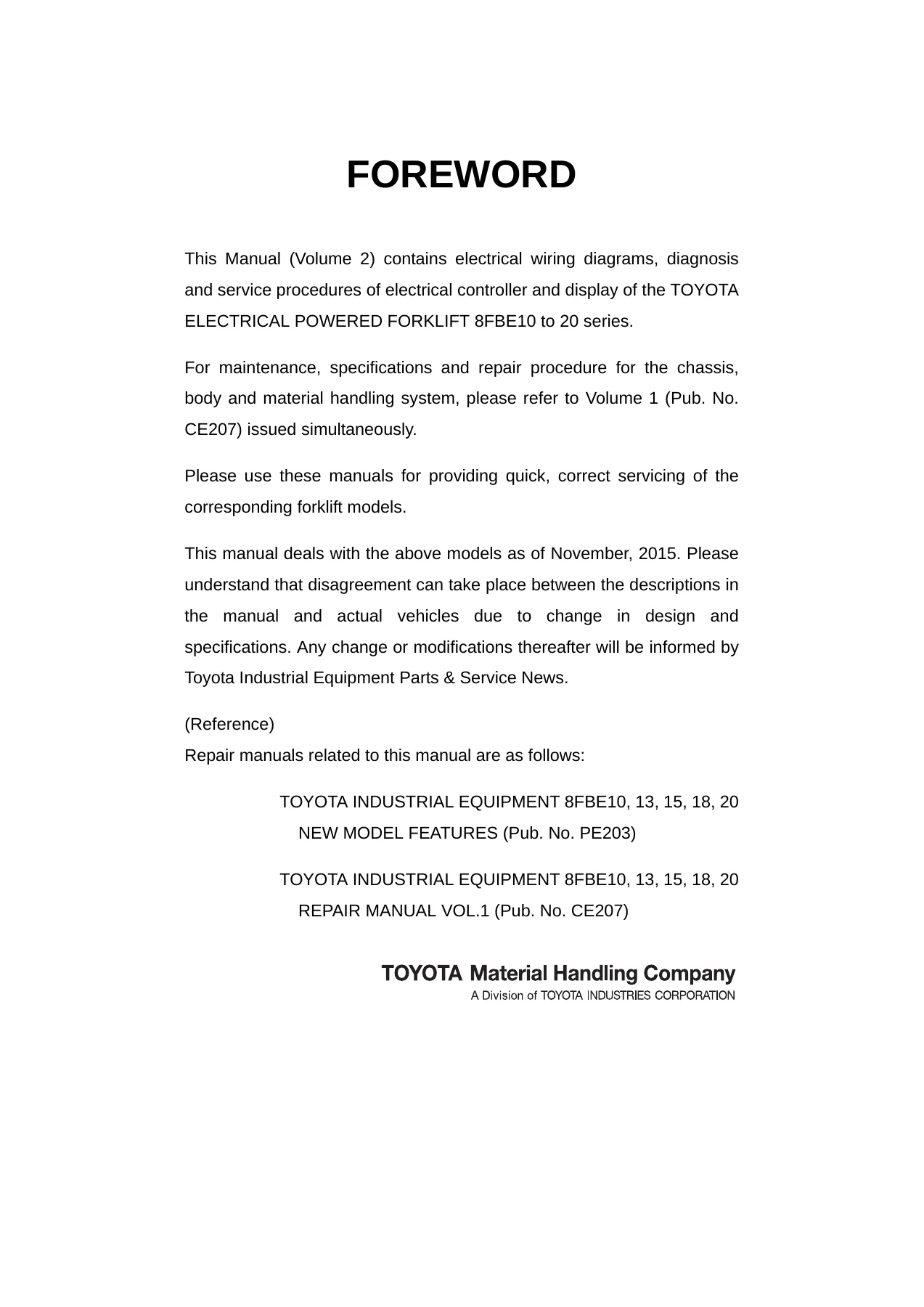
Volume 2 repair manual for the Toyota 8FBE10, 8FBE13, 8FBE15, 8FBE18 and 8FBE20 electric forklifts. Covers the on-vehicle charger, controller, motor drivers, contactor panel, multifunction display, service functions, analyzer, tuning, matching and complete diagnosis code troubleshooting. Pub. No. CE208.
Description
Toyota 8FBE10-20 Electric Forklift Repair Manual Volume 2 – CE208
The Toyota 8FBE10-20 Electric Forklift Repair Manual Volume 2 (Pub. No. CE208) covers the electrical controller and display systems of the Toyota 8FBE10, 8FBE13, 8FBE15, 8FBE18 and 8FBE20 series electrical powered forklifts. This is the electrical volume released alongside Volume 1 (Pub. No. CE207, chassis, body and material handling system) and is the reference a technician needs when working on the charger circuit, the inverter-based controller system, the CAN-linked multifunction display or any of the electrical fault codes that can appear on the operator screen. The manual reflects the model as of November 2015 and was published by Toyota Material Handling Company, a Division of Toyota Industries Corporation.
What This Toyota 8FBE10-20 Repair Manual Volume 2 Contains
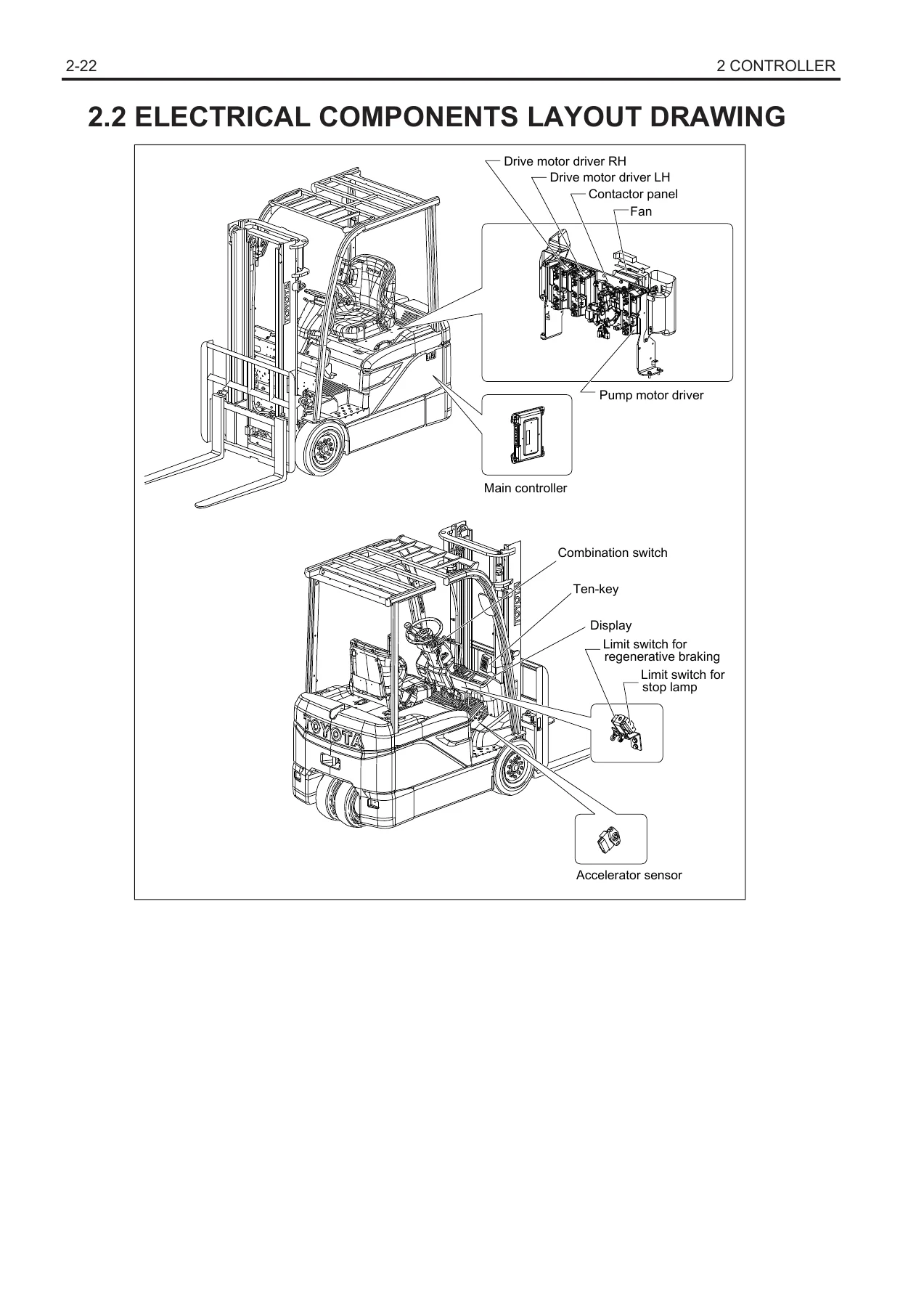
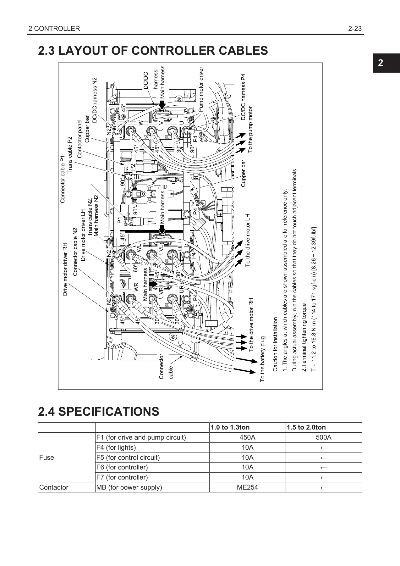
The content is organised into five top-level sections. The first section covers the charger – general information, the on-vehicle charger layout, the applicable charger list, charger specifications, charger panel components, the charger circuit diagram, tap changer adjustment, the magnet switch assembly, transformer assembly, and the timer test procedure. The second section covers the controller – general system configuration, the electrical components layout drawing, the controller cable layout with terminal torque references, controller specifications and fuse assignments, controller components, the before-inspection insulation resistance check, the connector inspection procedures for CN101, CN102, CN103, CN104, CN109, CN110, CN111, CN136, CN137, CN70, CN33, CN100, CN68, CN69 and CN35, disassembly procedure, the main controller and its connector pin assignment, drive and pump motor drivers, the contactor panel including its reassembly drawing, F1 fuse orientation, lapping sequence and insulating resistance test, cooling fan, display, combination switch, accelerator sensor (potentiometer) with matching, brake switch adjustment and OCL measurement for the drive circuit.
The third section covers the display – general information, screen layout, detailed descriptions of each indicator, the setting function and power select, the service function list, password entry, analyzer menu (diagnostic memory, I/O monitor 1 to 5, active test, program version), tuning, option set, matching (drive, SAS, lever, OCV, tire data, power off, speed) and the others menu. The fourth section is the troubleshooting volume – before-troubleshooting and connector handling, the SST list, the complete diagnosis code list with probable causes, related portions and step-by-step flow for every error code from A0-1 through to the safety monitor low-temperature codes, plus the when-no-error-code-is-displayed diagnostic tables covering power supply, traveling, load handling, steering, OPS, buzzer, auxiliary equipment, battery protection, shock detection and operator recognition. The fifth section is the appendix – SST list, service standards, connector drawings and connector locations.
File Details
- Manual type: Repair Manual (Volume 2 of 2) – electrical controller, charger and display
- Brand: Toyota / Toyota Material Handling Company
- Models covered: 8FBE10, 8FBE13, 8FBE15, 8FBE18, 8FBE20
- Publication number: CE208
- Related publications referenced: CE207 (Volume 1), PE203 (New Model Features)
- Date of coverage: November 2015
- Language: English
- Page count: 741
- File format: PDF
Chapters Covered
- 1 CHARGER – General, On-Vehicle Charger, Applicable Charger List, Specifications, Components, Circuit Diagram, Charger Panel, Before Charging, Magnet Switch ASSY, Transformer ASSY, Timer Test
- 2 CONTROLLER – General, Electrical Components Layout Drawing, Layout of Controller Cables, Specifications, Components, Before Inspection, Connector Inspection, Disassembly Procedure, Main Controller, Drive and Pump Motor Driver, Contactor Panel, Cooling Fan, Display, Combination Switch, Accelerator Sensor (Potentiometer), Brake Switch Adjustment, OCL Measurement
- 3 DISPLAY – General, Screen, Detail Description, Setting Function, Service Functions, Password, Analyzer, Tuning, Option Set, Matching, Others Menu
- 4 TROUBLESHOOTING – Before Troubleshooting, SST, Diagnosis Code List, When Error Code Is Displayed, When No Error Code Is Displayed
- 5 APPENDIX – SST List, Service Standards, Connector Drawing, Connector Location
Each of these sections is written for a technician who already has the truck in front of them and needs the correct procedure, connector pinout, voltage reading, resistance value or fault flow. The connector inspection tables give the standard voltages and resistance values for every pin of the main controller, the drive motor drivers, the pump motor driver, the display, the CAN bridge, the charger switch box, the ten-key pad, the accelerator sensor, the tire angle sensor, the steering angle sensor and the lift, tilt, attachment 1 and attachment 2 lever potentiometers on both conventional lever and mini lever / joystick versions. The diagnosis section does not stop at the code list – every diagnostic code is followed by a probable cause list, a related portion diagram, and a numbered sequence of inspection steps with a judgment table telling you what to do at each branch.
Why This Toyota 8FBE10-20 Service Manual Volume 2 Matters
On the 8FBE series, the electrical system is where most of the diagnostic time gets spent. The main controller, the drive motor driver LH and RH, and the pump motor driver all sit on the same CAN bus as the display, and they share responsibility for travel, load handling, power steering, OPS, regenerative braking and the charger interface. A general-purpose electrical guide will not get you to the right connector pin, will not tell you the correct test voltage for VRA1 versus VRA2, and will not tell you that a C4-6 accelerator matching code has a different cause and repair path than a C4-5 offset code. This manual does. It gives you the standard values, the exact CN connector pin numbers, the SST part numbers for accurate measurement, the tightening torque for the copper bars, motor cables and steering wheel nut, and the correct procedure for the timer test, the OCL current measurement, the matching sequence for the accelerator sensor, and the tap changer setting on the charger transformer.
Who This Manual Is For
This Toyota 8FBE10-20 electric forklift repair manual is written for the service technician, the fleet maintenance manager and the technically-minded owner-operator who needs factory-level information on the charger, the controller, the display and the fault diagnostics. It is equally useful whether you are chasing a single diagnostic code, replacing a motor driver, rewiring a harness, adjusting the brake switch, matching a new accelerator potentiometer, setting the tire data after a wheel change, or simply trying to understand what the spanner indicator on the display is trying to tell you. Because the manual is organised by error code as well as by system, it works as a lookup tool during a fault call as well as a reference for planned maintenance and component replacement.
IMAGES PREVIEW
Instant PDF Delivery
The manual is supplied as an instant-download PDF, so there is no shipping, no waiting and no courier. It can be opened on a workshop laptop, a tablet at the truck or a phone in the yard, and the pages can be printed for the section you are working on. Once you own the Toyota 8FBE10-20 Repair Manual Volume 2 (CE208), you have the reference for the electrical half of these trucks for as long as you keep the file. It is the volume that pairs with CE207 (Volume 1) to give the complete repair manual set for the 8FBE10, 8FBE13, 8FBE15, 8FBE18 and 8FBE20 series.
Reviews
There are no reviews yet.