Description
File Details
- Manual type: Operating instructions and spare parts list
- Manufacturer: TTS-LMG Marine Cranes GmbH, Marine Crane Division
- Model: Single Deck Crane KL 30T – 28M
- TTS Yard Nos.: 2-571-7/3398 – 7/3401
- Year of construction: 2009
- Classification society: LR
- Document date: April 2010
- Nantong Huatai Hull No.: H0002
- Language: English
- File format: PDF
Chapters Covered in the TTS-LMG KL 30T-28M Manual
- Preface – safety regulations, prohibition, warning, mandatory and rescue signs, safety devices (brakes, lighting, limit switches), fire extinguishing procedures and emergency exit escape device instructions
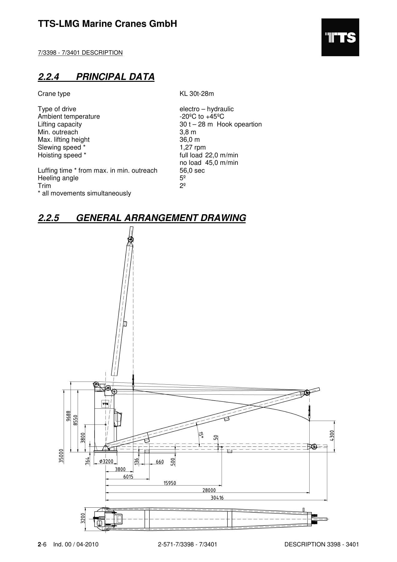
- Crane description – tower, cabin, jib, slew assembly, hydraulic system, hoisting and luffing gears, slewing gear, electrical equipment, technical data, operating conditions, load limitation depending on outreach, principal data, general arrangement drawing, power supply, electric motors, splitter gearbox, slewing ring and reducer, winches, ropes and weights
- Operation – preparatory works, setting of grab and hook operation, monitoring devices, control desks, control levers (joysticks), interactive dialogue system (display), safety regulations, putting into operation, tandem operation mode, closing down
- Maintenance – general remarks, checking oil levels and oil changes, lubricants, electrical equipment, hydraulic equipment, slewing gear, hoisting and luffing gear, winch drive 7C series, greasing points and oil change schedules
- Specification of the electrical equipment – technical data, general description, supply sources, main switch, crane operation, switch gear, sensors, limit switches, PLC, display and indicators, dialogue module operation, commissioning and adjustments, crane operation modes, interlocking for sea voyage, PMS power management, special operation modes, trouble shooting list of fault messages, emergency operation system
- Spare parts list – assembly groups covering deck crane, slewing tower, jib, rope plan, cargo block, panel list, parts without attachment, driving house, winch module, electrical equipment, hydraulic system and technical documents
- Assembly instruction – preparation of foundation column, unloading and putting up crane tower, filling gear reducers and hydraulic system, mounting the crane tower, fitting access ladder, fitting jib, reeving of ropes and cables, rope layouts, fitting remaining plates, installation of remaining components, lubricants recommendation and terminal connecting plan
The TTS-LMG KL 30T-28M Single Deck Crane operating instructions and spare parts list is the full factory documentation set issued for this electro-hydraulic marine deck crane. It combines a step-by-step operating guide, a detailed maintenance programme, complete electrical and hydraulic equipment specifications, and an illustrated spare parts catalogue broken down by assembly group, so a chief engineer, crane technician or shipyard fitter can work on the crane from a single reference. The manual opens with the safety framework that governs every intervention on the machine, then walks through the physical construction of the crane, its control desks and joystick behaviour, and the display-driven interactive dialogue system before moving into maintenance routines and part identification. Every section is written specifically for the KL 30T – 28M, so procedures, limit values and part numbers are matched to this crane and not to a generic deck crane family.
What the TTS-LMG KL 30T-28M Operating Instructions Manual Gives You
Because the TTS-LMG KL 30T-28M deck crane is an electro-hydraulic machine with three closed hydraulic circuits and a PLC-monitored control system, the operating manual spends real space on how the machine behaves in service: how the hoisting, luffing and slewing drives respond to the control levers, how the brakes release and apply, how the oil pre-heating and cooling systems are triggered, and how fault and condition messages appear on the display. That is the kind of detail that lets a duty engineer diagnose a sluggish slew, a hoist that will not lift, or a luffing drive that stops short of maximum outreach without having to call the manufacturer.
Complete PDF Bookmark Tree
Complete Bookmarks
The complete bookmarks in the “TTS-LMG KL 30T-28M Single Deck Crane Operating Instructions and Spare Parts List” are as follows:
+SINGLE DECK CRANE KL 30 T – 28Mp. 1
LIST OF CONTENTSp. 2
+1.0 PREFACEp. 4
1.1 PREFACEp. 5
1.2 SAFETY REGULATIONS – GENERAL REMARKSp. 6
+1.3 EXPLANATION OF SAFTY SIGNSp. 7
1.3.1 PROHIBITION SIGNSp. 7
1.3.2 WARNING SIGNSp. 7
1.3.3 MANDATORY SIGNSp. 8
1.3.4 RESCUE SIGNSp. 9
+1.4 SAFETY DEVICES – GENERAL REMARKSp. 10
1.4.1 BRAKESp. 10
1.4.2 LIGHTINGp. 10
1.4.3 LIMIT SWITCHESp. 10
1.4.4 SAFETY DEVICESp. 10
+1.5 SAFETY REGULATIONSp. 11
1.5.1 FIRE EXTINGUISHER SYSTEM / FIRE EXTINGUISHERp. 11
1.5.2 OPERATING INSTRUCTION FOR EMERGENCY EXIT WITH ESCAPE DEVICEp. 13
+2.0 DESCRIPTIONp. 14
+2.1 GENERALp. 15
2.1.1 CRANE TOWERp. 15
2.1.2 CRANE CABINp. 15
2.1.3 JIBp. 15
2.1.4 SLEW ASSEMBLYp. 15
2.1.5 HYDRAULIC SYSTEMp. 15
2.1.6 HOISTING AND LUFFING GEARSp. 15
2.1.7 SLEWING GEARp. 15
2.1.8 ELECTRIC EQUIPMENTp. 15
+2.2 TECHNICAL DATAp. 16
2.2.1 OPERATING CONDITIONS FOR DECK CRANESp. 16
2.2.2 CRANE LAYOUT – MAIN DIMENSIONp. 17
2.2.3 LOAD LIMITATION DEPENDING ON OUTREACHp. 18
2.2.4 PRINCIPAL DATAp. 19
2.2.5 GENERAL ARRANGEMENT DRAWINGp. 19
2.2.6 POWER SUPPLYp. 20
2.2.7 ELECTRIC MOTORSp. 20
2.2.8 SPLITTER GEARBOXp. 20
2.2.9 SLEWING RINGp. 20
2.2.10 SLEWING GEAR REDUCERp. 20
2.2.11 WINCHESp. 21
2.2.12 ROPESp. 21
2.2.13 WEIGHTSp. 22
+3.0 OPERATION INSTUCTIONp. 23
+3.1 PREPARATORY WORKSp. 24
3.1.1 OPERATION INSTRUCTIONS AND AFETY REGULATIONSp. 24
3.1.2 SETTING OF GRAB/HOOK OPERATIONp. 25
3.1.3 MONITORING DEVICESp. 26
+3.2 GENERAL OPERATION MANUALp. 27
3.2.1 CONTROL EQUIPMENT FOR DECK CRANE-CONTROL DESKp. 27
3.2.2 CONTROL LEVER (YOY STICKS)p. 31
3.2.3 INTERACTIVE DIALOGUE SYSTEM (DIPLAY)p. 34
+3.3 CRANE OPERATIONp. 36
3.3.1 SAFATY REGULATIONSp. 36
3.3.2 SETTING OF GRAB/HOOK OPERATIONp. 37
+3.3.3 PUTTING INTO OPERATIONp. 38
3.3.3.1 TANDEM OPERATION MODE OF DECK CRANEp. 44
3.3.4 CLOSING DOWNp. 45
+4.0 MAINTENACEp. 48
+4.1 GENERAL REMARKSp. 50
4.1.1 CHECKING OIL LEVELS, OIL CHANGESp. 51
4.1.2 VISIBLE OIL LOSSESp. 51
4.1.3 OIL, GREASES AND HYDRAULIC OILSp. 51
4.1.4 FILTERSp. 51
4.1.5 SEALS AND GASKETSp. 51
4.1.6 SEALING SURFACESp. 51
4.1.7 THREADED PIPE CONNECTORS, HOSESp. 51
4.1.8 GREASES LUBRICATIONp. 51
4.1.9 GREASINGp. 52
4.1.10 MARKING OF PARTSp. 52
4.1.11 REPLACEMENT UNITSp. 52
4.1.12 AFTER MAINTENANCE WORKp. 52
4.1.13 INSPECTION OF THE HOOKp. 52
4.1.14 ROPE – HOISTING AND LUFFING ROPEp. 53
4.1.15 ROPE _ INSPECTIONp. 55
4.1.16 MULTI – DISC BRAKES / MOTOR SHAFT DOGp. 56
+4.1.17 SLEWING GEARp. 57
+4.1.17.1 GENERAL INFORMATIONp. 58
4.1.17.1.1 MANUEL AIMp. 58
4.1.17.1.2 INFORMATION ON SAFETYp. 58
4.1.17.2 LIFTING AND HANDLINGp. 59
+4.1.17.3 INSTALLATIONp. 60
4.1.17.3.1 HYDRAULIC MOTOR INSTALLATIONp. 60
4.1.17.3.2 INSTALLATION OF THE SLEW DRIVE ON THE MACHINEp. 61
4.1.17.3.3 CONNECTION OF THE BRAKEp. 62
4.1.17.3.4 CONNECTION OF THE DRAINING PORTp. 63
4.1.17.3.5 REPLACING OF THE BREATHER VALVE AS LOOSE PARTp. 63
+4.1.17.4 LUBRICATIONp. 64
4.1.17.4.1 GEARBOX LUBRICATIONp. 64
4.1.17.4.2 OIL FILLINGp. 65
4.1.17.4.3 OIL DRAINING AND REPLACEMENTp. 65
4.1.17.5 START UP AND RUNNING INp. 66
4.1.17.6 MAINTENANCEp. 67
+4.1.18 HOISTING AND LUFFING GEARp. 68
+4.1.18.1 WINCH DRIVEp. 69
4.1.18.1.1 MANUAL AIMp. 69
4.1.18.1.2 INFORMATION ON SAFETYp. 70
+4.1.18.2 INSTALLATIONp. 71
4.1.18.2.1 DIRECTION OF ROTATINGp. 71
4.1.18.2.2 CONSTRUCTION OF THE DRUM FRAMEp. 72
4.1.18.2.3 HYDRAULIC MOTOR INSTALLATIONp. 73
4.1.18.2.4 INSTALLATION OF THE GEARBOX ON THE WINCHp. 76
4.1.18.2.5 CONNECTION OF THE BRAKEp. 77
+4.1.18.3 LUBRICATIONp. 78
4.1.18.3.1 GEARBOX LUBRICATIONp. 78
4.1.18.3.2 OIL FILLINGp. 79
4.1.18.3.3 OIL DRAINING AND REPLACEMENTp. 80
4.1.18.4 START UP AND RUNNING INp. 81
+4.1.18.5 MAINTENANCEp. 82
4.1.18.5.1 TROUBLE SHOOTINGSp. 83
4.1.19 GREASING POINTS – CRANEp. 86
4.1.20 OIL CHANGEp. 87
4.2 MAINTENANCE SCHEULEp. 88
4.3 LUBRICANTSp. 90
+4.4 ELECTRICAL EQUIPMENTp. 91
4.4.1 SAFETY DEVICESp. 91
4.4.2 LIGHTINGp. 92
4.4.3 MOTORSp. 92
4.4.4 SLIPRING BODIESp. 92
4.4.5 CIRCUIT BREAKERSp. 92
+4.5 HYDRAULIKEQUIPMENTp. 94
+4.5.1 FUNCTIONAL DESCRIPTIONp. 97
4.5.1.1 HOISTING GEAR CIRCUIT 1.0p. 97
4.5.1.2 LUFFING GEAR CIRCUIT 2.0p. 99
4.5.1.3 SLEWING GEAR CICUIT 3.0p. 99
4.5.1.4 BOOSTING AND CONTROL OIL CIRCUIT 4.0p. 100
4.5.1.5 OIL COOLING 5.0p. 103
4.5.1.6 HYDRAULIC OIL TANK 6.0p. 103
4.5.1.7 FILLING 7.0p. 103
4.5.1.8 EMERGENCY OPERATIONp. 104
+4.5.2 GENERAL REMARKSp. 106
4.5.2.1 PUTTING SYSTEMS INTO OPERATION ( BY WORKS PERSONNEL )p. 108
4.5.2.2 INSPECTION AND MAINTENANCEp. 109
+4.5.2.3 OPERATION AND MAINTENANCE OF HYDRAULIC PUMPS AND MOTORSp. 112
4.5.2.3.1 GENERAL REMARKSp. 112
4.5.2.3.2 INSTALLATIONp. 112
4.5.2.3.3 FIRST STARTp. 112
4.5.2.3.4 ROUTINE MAINTENANCEp. 113
4.5.2.4 TROUBLESHOOTING
4.5.2.5 TROUBLESHOOTINGp. 114
+4.6 ASSEMBLY AND DISMANTLINGp. 119
4.6.1 GENERAL REMARKSp. 119
4.6.2 ROPE REPLACEMENTp. 122
4.6.3 HAND SIGNALS FOR CRANESp. 125
4.6.4 TIGHTENING TORQUES FOR HEXAGON BOLTS AND SPANNER BOLTSp. 126
4.6.5 INSTALLATION OF HOSESp. 127
+5.0 SPECIFICATION OF THE ELECTRICAL EQUIPMENTp. 128
5.1 TECHNICAL DATAp. 130
+5.2 GENERAL DESCRIPTIONp. 131
5.2.1 SUPPLY SOURCESp. 131
5.2.2 GENERAL DRIVE SYSTEM REMARKSp. 132
5.2.3 MAIN SWITCHp. 132
5.2.4 CRANE OPERATION ( NORMAL MODE )p. 133
5.2.5 SWITCH GEARp. 134
5.2.6 SENSORSp. 135
5.2.7 LIMIT SWITCHESp. 136
5.2.8 PROGRMMABLE LOGIC CONTROLLER (PLC)p. 137
+5.3 DISPLAY AND INDICATORSp. 138
5.3.1 INDICATOR LIGHTSp. 138
5.3.2 DISPLAY OF CRANE INFORMATIONSp. 138
+5.3.3 DIALOGUE MODULE ( OPERATING-, OBSERVE- AND INPUT PANEL )p. 139
5.3.3.1 OPERATION OF THE DIALOGUE MODULE OVER THE FUNCTION KEAYSp. 141
5.3.3.2 HOW TO ENTER MAIN MENUp. 141
+5.4 COMMISSIONING AND ADJUSTMENTSp. 148
5.4.1 GENERAL DEFAULT SETTINGp. 149
5.4.2 PLC CHANGEp. 150
5.4.3 SETTING THE MINIMUM CURRENT FOR SLEWING GEARp. 151
5.4.4 ADJUSTABLE WORKING RANGE LIMITATIONp. 152
+5.4.5 SETTING THE LIMIT SWITCHES (BASIC ADJUSTMENT)p. 153
5.4.5.1 SETTING LAYER CHANGE POSITIONp. 156
5.4.5.2 RESETTING OF REFERERENCE POSITIONSp. 157
5.4.5.3 FORCING OF REFERENCE POSITIONSp. 161
5.4.6 ADJUSTABLE WORKING RANGE LIMITATIONp. 162
5.4.7 SPECIAL MODUS FOR ROPE CHANGEp. 165
5.4.8 CALIBRATION OF LOAD INDICATIONp. 166
5.4.9 REPORT OF CHANGEp. 169
5.4.10 ZERO – SETTING OF POTENTIONMETERSp. 170
5.4.11 SETTING OF OPERATION HOUERSp. 170
5.4.12 ZERO – SETTING OF INCLINOMETERS (SPECIAL EQUIPMENT)p. 170
+5.5 CRANE OPERATION MODESp. 171
5.5.1 GRAB OPERATIONp. 171
+5.6 INTERLOCKING FOR SEA VOYAGEp. 173
5.6.1 LOCKINGp. 173
5.6.2 UNLOCKINGp. 174
+5.6.3 FAULT MESSAGES AND EMERGENCY OPERATION SYSTEMp. 175
5.6.3.1 SETTING THE PRESSURE LIMITING VALVEp. 178
5.6.3.2 LOCK / UNLOCK IN EMERGENCY OPERATIONp. 179
+5.7 PMS – POWER MANAGEMENT SYSTEM (SPECIAL EQUIPMENT)p. 180
5.7.1 FUNCTIONAL DESCRIPTIONp. 180
+5.8 SPECIAL OPERATION MODESp. 181
5.8.1 TEST OPERATIONp. 181
5.8.2 POWER / SPEED REDUCTIONp. 181
5.8.3 DISABLE TRIMOTp. 181
+5.9 TROUBLE SHOOTINGp. 182
+5.9.1 GENERAL REMARKSp. 182
5.9.1.1 FAULT INDICATIONSp. 182
5.9.1.2 CONDITION INDICATIONSp. 182
5.9.1.3 PLC STATUS INDICATORSp. 183
5.9.1.4 ADDITIONAL INDICATORSp. 183
5.9.2 LIST OF FAULT MESSAGESp. 184
5.10 EMERGENCY OPERATION SYSTEMp. 244
+5.11 SERVICEp. 246
5.11.1 MAINTENANCE INFORMATION FOR HYDRAULICp. 246
5.11.2 MAINTENANCE OF ELCTRICAL EQUIPMENTp. 247
5.11.3 SPARE PARTSp. 249
+5.12 APPENDIXp. 250
+5.12.1 DESCRIPTION OF THE ELECTRICAL COMPONENTSp. 250
5.12.1.1 MAIN SWITCH (LOAD BREAKER)p. 250
+5.12.1.2 GEARED LIMIT SWITCHESp. 257
5.12.1.2.1 ASSEMBLEY OF THE GEARED LIMIT SWITCHp. 258
5.12.1.2.2 CONTACT ADJUSTMENTp. 259
5.12.1.2.3 BLOCK ADJUSTMENTp. 260
5.12.1.3 PROGRAMMABLE LOGIC CONTROLLER (PLC)p. 261
5.12.1.4 COMPACT MODULE PWMp. 270
5.12.1.5 COMPACT MODULE DIGITAL / ANALOGEp. 278
5.12.1.6 CABINET – MODULEp. 286
5.12.1.7 INCLINOMETERp. 293
5.12.1.8 LCD – DISPLAYp. 298
5.12.2 CIRCUIT DIAGRAMp. 303
+6.0 CRANE 1 – 4 SPARE PARTS LIST CRANESp. 380
00.00.00.00 CRANE 1 DECK CRANE KL 30T – 28M ORDER-NO. 7/3398p. 381
00.00.00.00 CRANE 2 DECK CRANE KL 30T – 28M ORDER-NO. 7/3399p. 382
00.00.00.00 CRANE 3 DECK CRANE KL 30T – 28M ORDER-NO. 7/3400p. 383
+00.00.00.00 CRANE 4 DECK CRANE KL 30T – 28M ORDER-NO. 7/3401p. 384
+01.00.00.00 SLEWING TOWER COMPL.p. 385
01.10.00.00 PROTECTION FOR CABINp. 385
+01.12.00.00 ROPE PULLEYS RIGHT HAND COMPL.p. 386
01.12.01 ROPE PULLEY DIA 630 COMPL.p. 387
+01.15.00.00 ROPE PULLEYS COMPL.p. 388
01.15.01 ROPE PULLEY DIA 630 COMPL.p. 389
01.16.00.00 JIB BEARING DIA 160p. 390
+01.17.00.00 SLEWING GEAR COMPL.p. 392
+01.17.02.00 SLEWING GEARp. 393
+GENERALINFORMATIONp. 403
MANUAL AIMp. 403
INFORMATION ON SAFETYp. 403
LIFTING AND HANDLINGp. 404
+INSTALLATIONp. 405
HYDRAULIC MOTOR INSTALLATIONp. 405
INSTALLATION OF THE SLEW DRIVE ON THE MACHINEp. 406
CONNECTION OF THE BRAKEp. 407
CONNECTION OF THE DRAINING PORTp. 408
REPLACING OF THE BBREATHER VALVES AS LOOSE PARTp. 408
+LUBRICATIONp. 409
GEARBOX LUBRICATIONp. 409
OIL FILLINGp. 410
OIL DRAINING AND REPLACEMENTp. 410
START UP AND RUNNNG INp. 411
MAINTENANCEp. 412
+01.17.02.00 SLEWING GEARp. 413
+GENERALINFORMATIONp. 423
MANUAL AIMp. 423
INFORMATION ON SAFETYp. 423
LIFTING AND HANDLINGp. 424
+INSTALLATIONp. 425
HYDRAULIC MOTOR INSTALLATIONp. 425
INSTALLATION OF THE SLEW DRIVE ON THE MACHINEp. 426
CONNECTION OF THE BRAKEp. 427
REPLACING OF THE BBREATHER VALVES AS LOOSE PARTp. 428
+LUBRICATIONp. 429
GEARBOX LUBRICATIONp. 429
OIL FILLINGp. 430
OIL DRAINING AND REPLACEMENTp. 430
START UP AND RUNNNG INp. 431
MAINTENANCEp. 432
01.18.00.00 BALL BEARING SLEWING RING COMPL.p. 433
+01.23.00.00 OPENING FLAP COOLER CAPp. 434
01.23.01.00 FLAP COOLER CAP COMPL.p. 435
+01.31.00.00 ROPE PULLEYS DIA 630 COMPLp. 436
01.31.01 ROPE PULLEY DIA 630 COMPL.p. 437
+02.00.00.00 JIB CRANE 1 – 4 COMPL.p. 438
+02.00.00.00 JIB COMPL. CRANE 1p. 438
02.01.00.00 JIB STEEL STRUCTURE COMPL.p. 438
+02.04.00.00 ROPE PULLEYS COMPL.p. 445
02.04.01.01 ROPE PULLEY DIA 630 COMPL.p. 446
02.09.00.00 LAMP BRACKET L.H.p. 447
02.20.00.00 BUFFER STOPp. 448
+02.00.00.00 JIB COMPL. CRANE 2p. 440
02.01.00.00 JIB STEEL STRUCTURE COMPL.p. 440
+02.04.00.00 ROPE PULLEYS COMPL.p. 445
02.04.01.01 ROPE PULLEY DIA 630 COMPL.p. 446
02.09.00.00 LAMP BRACKET L.H.p. 447
02.20.00.00 BUFFER STOPp. 448
+02.00.00.00 JIB COMPL. CRANE 3p. 442
02.01.00.00 JIB STEEL STRUCTURE COMPL.p. 442
+02.04.00.00 ROPE PULLEYS COMPL.p. 445
02.04.01.01 ROPE PULLEY DIA 630 COMPL.p. 446
02.09.00.00 LAMP BRACKET L.H.p. 447
02.20.00.00 BUFFER STOPp. 448
+02.00.00.00 JIB COMPL. CRANE 4p. 444
02.01.00.00 JIB STEEL STRUCTURE COMPL.p. 444
+02.04.00.00 ROPE PULLEYS COMPL.p. 445
02.04.01.01 ROPE PULLEY DIA 630 COMPL.p. 446
02.09.00.00 LAMP BRACKET L.H.p. 447
02.20.00.00 BUFFER STOPp. 448
05.00.00.00 ROPE PLAN KL 30T – 28Mp. 449
+07.00.00.00 CARGO GEARp. 452
07.01.00.00 CARGO BLOCK SWL 35T COMPL.p. 454
07.02.00.00 GRAB MOUNTINGp. 458
12.00.00.00 PANEL LIST SLEWING TOWERp. 459
+14.00.00.00 PARTS WITHOUT ATTACH IN WORKp. 462
14.02.00.00 EXTHINGUISHERp. 462
14.03.00.00 ROPE DOWN DEVICEp. 462
+14.25.00.00 E-PARTS WITHOUT ATTACH IN WORKp. 463
14.25.20.00 SLIPRING BODYp. 464
14.25.21.00 ACCESSORIES FOR SLIP-RINGp. 469
14.25.30.00 FLOODLIGHT 1x1000W HAL.p. 469
14.25.32.00 EMERGENCY STOP FROM DECK AREAp. 470
+18.00.00.00 DRIVING HOUS COMPL.p. 471
18.02.00.00 CABIN COMPONENTSp. 473
+19.00.00.00 WINCH MODULE COMPL.p. 690
+19.01.00.00 WINCH MODULEp. 694
+19.01.01.00 LUFFING GEAR WINCH COMPL.p. 695
+19.01.01.01 LUFFING GEARp. 698
+GENERAL INFORMATIONp. 705
MANUEL AIMp. 705
INFORMATION ON SAFETYp. 706
+INSTALLATIONp. 707
DIRECTION OF ROTATIONp. 707
CONSTRUCTION OF THE DRUM FRAMEp. 708
HYDRAULIC MOTOR INSTALLATIONp. 709
INSTALLATION OF THE GEARBOX ON THE WINCHp. 712
CONNECTION OF THE BRAKEp. 713
+LUBRICATIONp. 714
GEARBOX LUBRICATIONp. 714
OIL FILLINGp. 715
OIL DRAINING AND REPLACEMENTp. 716
START UP AND RUNNING INp. 717
MAINTENANCEp. 718
TROUBLE SHOOTINGp. 719
+19.01.02.00 HOISTING GEAR WINCH COMPL.p. 723
19.01.02.01 HOISTING GEARp. 726
19.01.02.01 HOISTING GEARp. 734
GENERAL INFORMATIONp. 741
19.01.08.00 PRESSURE ROLLERp. 742
19.01.08.00 PRESSURE ROLLERp. 743
19.01.17.00 WINCH UNIT STEEL COMPL.p. 744
19.32.00.00 LIMIT SWITCH SLACK ROPEp. 745
+25.00.00.00 ELECTRICAL EQUIPMENT COMPL.p. 476
+25.01.00.00 E-PART SLEWING TOWERp. 477
25.01.03.00 LIGHTING AND HEATINGp. 477
+25.01.60.00 MOUNTING IN WORKSHOPp. 478
25.01.60.01 PROTECTION EARTHINGp. 478
25.02.00.00 E-SYSTEM JIBp. 479
+25.15.00.00 E-SYSTEM AGGREGATE MODULEp. 480
25.15.03.00 LIGHTINGp. 480
+25.15.10.00 PUMP DRIVE UNITp. 481
25.15.10.01 E-MOTORp. 482
+25.15.10.60 INSRALLATION POWER PACKp. 491
25.15.10.60.01 DIGITAL MODULEp. 492
25.15.10.60.02 ANALOG MODULEp. 492
25.15.10.60.03 COMPACT MODULEp. 492
25.15.15.00 LIMIT SWITCH FOR WINCHESp. 493
+25.15.50.00 CONTROL CABINETp. 493
25.15.50.01 CABINETp. 494
+25.15.50.02 EQUIPMENT PART =M01p. 495
25.15.50.02.06 PILOT LAMP POWER SUPPLY COMPL.p. 496
25.15.50.02.07 PILOT LAMP AUX. SUPPLY COMPL.p. 496
25.15.50.03 EQUIPMENT PART =M02p. 497
25.15.50.04 EQUIPMENT PART =M03p. 498
25.15.50.05 EQUIPMENT PART =M06p. 499
25.15.50.05.01 PLC R360p. 499
25.15.50.06 STANDARD INSTALLATIONp. 500
25.15.60.00 WORKSHOP INSTALLATIONp. 501
+25.18.00.00 ELECTRICAL EQUIPMENT CABINp. 502
25.18.02.00 CABIN BUILT INp. 502
+25.18.10.00 CONTROL DESK LEFT COMPL.p. 503
25.18.10.01 HOUSINGp. 503
+25.18.10.03 CONTROL EQUIPMENTp. 504
25.18.10.03.02 SELECTOR SWITCH WORKING LIGHTp. 505
25.18.10.03.03 SELECTOR SWITCH CABIN LIGHTp. 505
25.18.10.03.04 SELECTOR SWITCH RED WARNING LIGHTp. 506
25.18.10.03.05 SELECTOR SWITCH CABIN HEATINGp. 506
25.18.10.03.06 SELECTOR SWITCH SCREEN WIPERp. 507
+25.18.20.00 CONTROL DESK RIGHTp. 508
25.18.20.01 HOUSINGp. 508
+25.18.20.02 CONTROL EQUIPMENTp. 509
25.18.20.02.10 EMErGENCY STOP BUTTONp. 510
25.18.20.02.11 KEY-OPERATED BUTTON JIB RESTINGp. 510
25.18.20.02.12 PILOT LIGHT FAULTp. 511
25.18.20.02.13 SELECTOR SWITCH OFF/ONp. 511
25.18.20.02.14 SELECTOR SWITCH GRAB PERATIONp. 512
25.18.20.80.00 EXPANSION SMAG-GRAB CONTROLp. 512
25.18.60.00 WORKSHOP INSTALLATIONp. 513
+66.00.00.00 HYDRAULIC SYSTEM COMPL.p. 514
+66.01.00.00 HYDRAULIC SYSTEM SLEWING TOWERp. 516
66.01.02.00 COMPONENTS HYDRAULIC SYSTEMp. 517
+66.01.13.00 HYDRAULIC MOTOR SLEWING GEAR COMPL.p. 519
+66.01.13.01 HYDRAULIC MOTOR SLEWING GEARp. 520
66.01.13.01.01 AXIAL PISTON UNIT SCM 056p. 522
66.01.13.01.02 SOCKET PIECEp. 528
+66.01.13.03 HYDRAULIC MOTOR SLEWING GEARp. 529
66.01.13.02.02 SOCKET PIECEp. 530
+66.15.00.00 HYDRAULIC SYSTEM AGGREGATE MODULEp. 531
+66.15.01.00 HYDRAULIC AGGREGATE COMPL.p. 532
66.15.01.01 DISTRIBUTION GEARp. 533
66.15.01.02 FASTENING PARTS FOR DISTRIBUTION GEARp. 535
66.15.01.03 DAMPERp. 536
+66.15.01.04 HYDRAULICAGGREGATEp. 538
66.15.01.04.01 VAR. DISPL. PUMP A4VG 125p. 542
66.15.01.04.01 VAR. DISPL. PUMP SH6V 130p. 558
NOTICEp. 573
66.15.01.04.03 VAR. DISPL. PUMP A4VG 125p. 574
66.15.01.04.03 VAR. DISPL. PUMP SH6V 130p. 588
NOTICEp. 604
+66.15.20.00 HYDRAULIC TANK COMPONENTSp. 605
66.15.20.01 FILTER AND LEACK OIL COLLECTING BLOCKp. 610
66.15.20.03 FILTER AND CONTROL STATIONp. 614
+66.15.21.00 PUMP AGGREGAT COMPL.p. 617
66.15.21.01 TANK COVERp. 618
66.15.21.02 FUEL FEED AND CONTROL PUMPp. 620
+66.19.00.00 HYDRAULIC SYSTEM WINCH MODULEp. 623
66.19.02.00 COMPONENTS HYDR: SYSTEM WINCH MODULEp. 624
+66.19.10.00 HYDRAULIC MOTOR HOISTING GEAR COMPL.p. 625
66.19.10.01 ADJUSTABLE OIL MOTOR A6VM 200p. 626
+66.19.11.00 HYDRAULIC MOTOR LUFFING GEAR COMPL.p. 636
66.19.11.01 AXIAL PISTON UNITp. 638
66.19.11.02 SOCKET PIECEp. 645
+97.00.00.00 TECHNICAL DOKUMENTSp. 646
97.01.00.00 TECHNICAL DOKUMENTSp. 646
97.25.00.00 ELECTRICAL DOKUMENTATIONp. 646
+97.66.00.00 HYDRAULIC DOKUMENTATIONp. 646
97.66.01.00 HYDRAULIC DIAGRAMp. 647
97.66.02.00 LIST OF PARTS FOR HYDR:. DIAGRAMp. 648
97.66.03.00 LIST OF HOSESp. 662
+7.0 ASSEMBLY INSTRUCTIONp. 665
7.1 ASSEMBLY INSTRUCTIONp. 666
7.2 ASSEMBLY AND PUTTING INTO SERVICE OF THE CRANEp. 667
7.3 PREPARATION OF FOUNDATION COLUMNp. 669
+7.4 UNLOADING AND PUTTING UP CRANE TOWERp. 671
7.4.1 UNLOADING OF CRANE TOWERp. 671
7.4.2 PUTTING THE CRANE UPRIGHTp. 672
7.5 FILLING OF THE GEAR REDUCERS AND THE HYDRAULICp. 673
7.6 MOUNTING OF THE CRANE TOWERp. 674
7.7 FITTING THE ACCESS LADDER INTO THE FOUNDATION COLUMN/CRANE TOWERp. 675
7.8 SCHEMATIC DIAGRAM OF CONNECTIONp. 675
7.9 FITTING THE JIBp. 676
+7.10 REEVING OF ROPES AND CABLEp. 677
7.10.1 ROPE LAYOUT FOR LUFFING GEARp. 678
7.10.2 ROPE LAYOUT FOR HOISTING GEARp. 678
7.10.3 HOISTING AND LUFFING ROPE END FASTENING ON THE WINCHESp. 679
7.10.4 HOISTING AND LUFFING ROPE END FASTNING ON CRANE AND JIBp. 679
7.11 FITTING THE REMAINING PLATESp. 680
7.12 INSTALLATION OF REMAINING COMPONENTSp. 680
7.13 LUBRICANTS RECOMMENDATIONp. 681
7.14 TERMINAL CONNECTING PLANp. 682
The maintenance chapters go further. They set out oil change intervals for the slewing gearboxes, the hoisting and luffing winch gearboxes and the hydraulic tank, describe the multi-disc brake checking procedure for holding torque, list the rope inspection and rejection criteria, and show the greasing points across the tower, jib and hook block with the lubricant types and intervals. The multi-disc brake and slewing gear chapters include the port positions, oil quantities and the procedure for refilling the brake with automatic transmission fluid after repair. Winch drive 7C series service information is included with the drum frame construction, hydraulic motor mounting and static sealing test requirements.
Electrical and Hydraulic Coverage
The electrical specification chapter is unusually complete for a crane manual of this class. It describes the 440 V / 60 Hz main supply, the 220 V auxiliary supply and the 24 V DC control voltage, the main switch with under-voltage release, the star-delta starting sequence for the 160 kW pump drive motor, the slip ring assembly, the sensors (pressure, temperature, rope length incremental encoders, inclinometer) and the PLC architecture with its CAN-BUS network and compact I/O modules. A full list of fault and condition messages is provided with remedial actions, which is the part most often needed on board. The emergency operation system and the code-secured service area are documented, including how to override specific fault messages and how to reset reference positions after a rope change or PLC replacement.
The hydraulic equipment chapter explains the three closed circuits (hoisting, luffing and slewing), the boosting and control oil circuit, the oil cooling circuit, the hydraulic oil tank and the emergency manual pump. Function descriptions, first-start procedures, running-in steps and troubleshooting tables are included, along with the hydraulic diagram, list of parts and a full hydraulic hose list keyed to the schematic positions. That makes it possible to trace a hose, identify a valve or locate a pressure switch without going back to the drawing office.
The Illustrated Spare Parts List
The spare parts section is organised by assembly group and covers the deck crane complete, slewing tower, jib, rope plan, cargo block, panel list, driving house, winch module, electrical equipment, hydraulic system and technical documents. Individual sub-groups include rope pulleys, jib bearings, slewing gear, slewing ring, flap cooler cap, cargo block and grab mounting, control desks, control levers, limit switches, hydraulic motors, variable displacement pumps, the hydraulic tank and filter components, the winch gears and the pressure roller. Each exploded view or parts list gives the position number, description, quantity, order number and drawing number, so a part can be identified from the diagram and ordered without guesswork. For owners of the crane as delivered under TTS Yard Nos. 2-571-7/3398 through 7/3401, this catalogue is the reference that ties the physical machine to the original part numbers.
Who This Manual Is Written For
The TTS-LMG KL 30T-28M operating instructions and spare parts list is intended for the crane driver, the ship’s maintenance personnel and the shore-based technician responsible for keeping the crane in class. It assumes the reader is already familiar with marine deck machinery and is working under the safety regulations of the flag state, the classification society and the ship’s own procedures. The manual itself states that crane operation and maintenance are to be carried out only by suitably trained and qualified personnel, and that the copy kept on board is to be available to the driver at all times. Nothing in the document replaces a formal training course, but everything in it is written to support the person who already has to run, maintain and repair this specific crane.
What You Can Do With This TTS-LMG KL 30T-28M PDF
With this manual on hand you can start, operate and shut down the KL 30T – 28M deck crane using the documented control sequence, including the warm-up procedure in cold conditions and the correct way to switch between hook and grab operation. You can carry out the scheduled maintenance on the slewing gearboxes, winches, hydraulic tank and ropes, and check the multi-disc brakes and limit switches as the manual requires. You can read fault codes off the display and work through the associated remedial actions, reset the reference positions after a rope change, and calibrate the load indication if a test weight shows a discrepancy. You can identify any part from the illustrated spare parts list and quote the correct TTS-LMG order number when contacting the manufacturer or a spare parts supplier. And you can hand the same document to a new crew member or a visiting class surveyor, because it covers the crane from the foundation column up to the jib head lamp bracket.
Why Having the Correct Manual Matters
Deck cranes are class items. Getting the operating limits wrong, bypassing a safety device without authorisation, or fitting a non-original part can affect the crane’s certification and, more seriously, the safety of the people working under the jib. The KL 30T – 28M manual was written by the crane manufacturer to define those limits, list the monitoring devices that must not be tampered with, and specify the parts and lubricants that keep the machine inside its design envelope. Fault messages on the display are only useful if you have the list that tells you what each one means and what to do about it, and the brake and limit switch checks only make sense against the procedures and values given in the maintenance chapters. This is the document that closes that gap.
Instant PDF Delivery
The TTS-LMG KL 30T-28M Deck Crane Operating Instructions and Spare Parts List is delivered as a PDF download immediately after payment. There is no physical shipment, no waiting for a courier and no risk of a printed copy going missing between the office and the vessel. The file can be opened on a laptop in the engine control room, on a tablet on the winch platform or on a phone during a quick check on deck, and any page can be printed and taken to the crane if a paper copy is easier to work from. Because the whole document travels in one file, the operating instructions, maintenance schedules, electrical fault list and spare parts catalogue stay together, which is exactly how they were meant to be used.




Reviews
There are no reviews yet.