
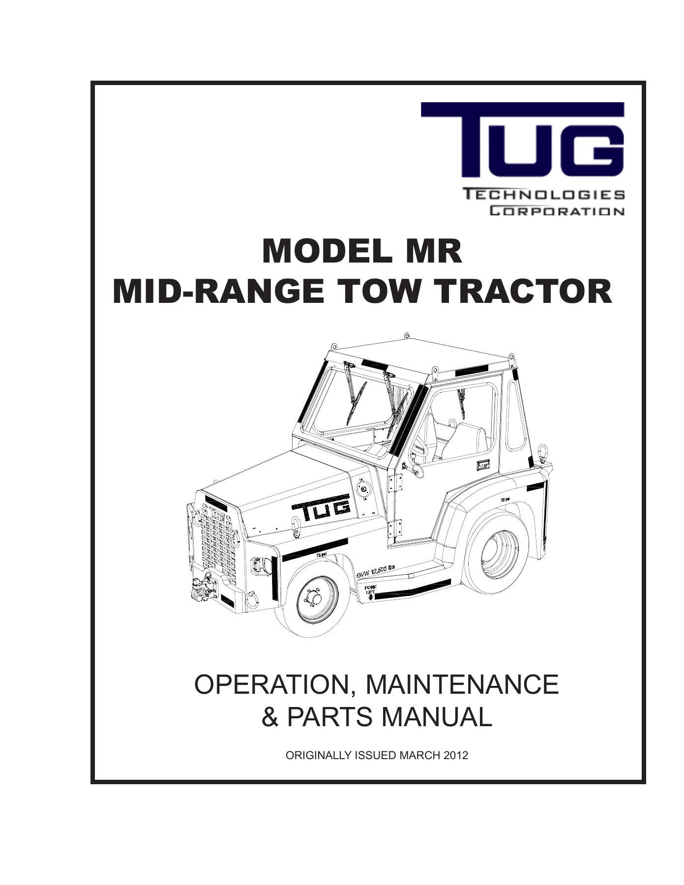
TUG MR Mid-Range Tow Tractor Operation, Maintenance & Parts Manual – PDF
Original price was: $39.95.$24.95Current price is: $24.95.
Complete operation, maintenance, troubleshooting, and illustrated parts manual for TUG MR Mid-Range Tow Tractors. Covers Deutz Tier 2, Deutz Tier 4i, and Kubota diesel engine variants, Ford C-6 and 4R75 transmissions, front steer axle, brake systems, hydraulics, electrical schematics, and full exploded parts diagrams. 1,198 pages. Document CD387.
Description
File Details
- Manual Type: Operation, Maintenance & Parts Manual
- Brand: TUG Technologies Corporation
- Model: MR Mid-Range Tow Tractor
- Covered Models: MR-8, MR-10, MR-24, MR-34, MR-36, MR10-24T, MR10-34T, MR10-36T, MR8-36
- Covered Engines: Deutz BF4M2011 (Tier 2), Deutz TD2011 L040 (Tier 4i), Kubota V3600T, Kubota V3600
- Covered Transmissions: Ford C-6 Automatic, Ford 4R75 Automatic
- Language: English
- Page Count: 1,198
- File Format: PDF
- Document Number: CD387
- Originally Issued: March 2012
Chapters Covered
- Introduction – Record of Revisions, List of Effective Pages, Manual Table of Contents, Copyright Notice, Unit Identification, Technical Assistance, Warranty Policy Statement, How to Use This Manual
- Safety – Discussion, Operator Responsibilities, Mechanic Responsibilities
- Chapter 1: General Information and Operating Instructions
- Section 1: Description – Braking System, Chassis, Coolant and Lubrication System, Electrical System, Engine, Drive Shaft, Air Intake System, Exhaust System, Fuel System, Ignition, Lights and Accessories, Seating, Hitches, Steering, Suspension, Tires and Wheels, Towing Capability, Transmission, Turning Radius
- Section 2: Operation – Principles of Operation, Operating Indicators and Controls, Dash Panel for Deutz Tier 2, Deutz Tier 4i, and Kubota engines, Operator’s Compartment, Preparation for Use, Standard Operating Procedures
- Section 3: Specifications – Engine, Transmission, Drive Axle, Steering, Front Axle, Wheels, Brakes, Electrical System, Towing Capability, Turning Radius
- Section 4: Shipping – Preparation, Battery, Fuel Tank
- Section 5: Storage – One to Six Months, Extended Period
- Chapter 2: Maintenance
- Section 1: Servicing – Preparation for Use, Periodic Maintenance Schedule (Daily, Initial 200 Hour, Every 6 Months, Yearly, Every Two Years), Lubrication Schematic, Standard Jacking Procedure, Alternator Belt Adjustment, Headlight Adjustment, Brake Bleeding Procedure, Stopping Distance Test, Hydraulic Flushing Procedure
- Section 2: Troubleshooting – General, Steering, Brake System, Electrical, Electrical Schematics, Hydraulic Schematic
- Section 3: Removal/Installation – Cab, Doors, Windows, Windshields, Wiper Motors, Hood Panel, Pintle Hitches, Seats, Seatbelts, Battery, Dash Panel Assembly, Gauges, Switches, Warning Light Assembly, Exterior Lamp Assemblies, Dome Light, Emergency Stop Switch, Electric Center Panel Assembly, Fuses, Relays, Power Block, Starter Relay, Circuit Breaker, Glow Plug Relay, Main Power Solenoid, Starter, Low Oil Pressure and High Oil Temperature Alarms, Horn Assembly, Fuel System, Accelerator and Modulator Assembly, Air Intake Assembly, Cooling Assembly, Exhaust System, Engine and Engine Components (Deutz Tier 2 QEC, Deutz Tier 4i QEC, Kubota QEC), Transmission Assembly, Front Axle/Suspension/Wheels, Drive Shaft/Drive Axle/Wheels, Brake System, Parking Brake Assembly, Hydraulic Power Steering System
- Chapter 3: Front (Steer) Axle
- Section 1: Recommended Overhaul Periods – General, Engine, Transmission, Front (Steer) Axle
- Section 2: Front (Steer) Axle – Axle Assembly, King Pin and Knuckles, Front Wheel Bearings, Front Leaf Springs and Shackles, Tie Rod End, Front Wheel Alignment
- Chapter 4: Illustrated Parts List
- Section 1: Description – Introduction, Using the Illustrated Parts List, Figure and Index Number, Part Numbers, Description and Quantity, Effectivity, Ordering Spare Parts
- Section 2: Illustrated Parts List – Frame Weldment, Access Panels, Hood Assembly, Cab Mounting, Cab Insulation, Cab Mirrors, Cab Door Installation, Driver Door Assembly, Passenger Door Assembly, Cab Windows, Windshield Wipers, Exterior Lamp Assemblies, Dome Light, Emergency Stop Switch Assembly, Lower Dash Access Panel, Seat Installation, Cab Heater Installation, Dash Assembly with Harness, Console Assembly, Alarm Assembly, Brake Pedal Assembly, Steering Column Assembly, Hydraulic Steering System, Front Suspension, Front (Steer) Axle Assembly, Hub and Rotor Assembly, Brake Calipers Assembly, Rear Suspension Assembly, Rear (Drive) Axle – Drain Plugs, Gear Set and Differential, Planetary Wheel End Drive, Wet Brakes System, Drop Box Drain Plugs, Front and Rear Wheel Assemblies, Accelerator and Modulator Cables, Engine and Transmission Installation, Engine Assembly, Front Engine Covers, Alternator Assembly, Starter Assembly, Timing Belt and PTO Assemblies, Hydraulic Pump PTO Drive Assembly, Oil Pan Installation, Air Intake Assembly, Fuel System, Exhaust System, Cooling System, Transmission Oil Pan Assembly, Transmission Filter Screen and Valve Body, Transmission Band Adjustment, Shifter Assembly, Shifter Linkage, Park Brake Lever Installation, Transmission Park Brake Assembly, Engine and Transmission Assembly (Deutz Tier 4i and 4R75), Transmission (4R75) Assembly, Transmission Sensors Installation, Transmission Oil Pan Installation (4R75), Shifter Assembly (4R75), Park Brake Assembly (4R75), Drive Shaft Assembly, Deutz Tier 4i ECU and 4R75 TCU Installation, VEC Panel Assembly, TEC Panel Assembly, Brake Line System, Hydroboost Installation, Battery Assembly, Heater Junction Box, Horn Installation
- Section 3: Numerical Index
- Section 4: Alphabetical Index
- Chapter 5: Additional Information & Publications
- Section 1: Periodic Maintenance Checklist
- Section 2: Additional Information & Publications
- Included Supplementary Manuals
- Deutz D/TD/TCD 2011 Engine Operation Manual – General, Engine Description, Operation, Operating Media, Maintenance, Care and Maintenance Work, Faults, Transport and Storage, Technical Data, Tools
- Ford 4R70E/4R75E Automatic Transmission Manual – General Specifications, Description and Operation, Diagnosis and Testing, Disassembly, Assembly, Removal, Installation, In-Vehicle Repair
- Murphy PowerView Model PV-101-C User’s Guide – Engine and Transmission Parameters, Faceplate Features, Navigation and Keypad Functions, Main Menu Options, Utilities Menu, OEM Menu, Faults and Warnings, Troubleshooting
What This Manual Provides
The TUG MR Mid-Range Tow Tractor Operation, Maintenance & Parts Manual is the definitive single-source reference for anyone responsible for operating, servicing, repairing, or maintaining TUG MR-series tow tractors. At 1,198 pages, this document goes far beyond a basic owner’s handbook. It combines operating instructions, scheduled maintenance procedures, troubleshooting diagnostics, step-by-step removal and installation sequences, complete specifications, wiring and hydraulic schematics, and a fully illustrated parts list with exploded views and numerical and alphabetical indexes. The factory-issued CD387 manual is structured so that a technician can move from a symptom to a diagnostic test, from a failed component to a removal procedure, from a part number to an exploded diagram, without leaving the document.
For the TUG MR tractor operator, Chapter 1 provides a complete familiarization with the machine. It explains the function of every gauge, switch, indicator light, and control across the three dash panel variants: the Deutz Tier 2 configuration, the Deutz Tier 4i configuration with Murphy PowerView display, and the Kubota configuration. It covers normal starting, cold weather starting with glow plug operation, driving instructions, towing instructions, and the principles of operation for the braking, steering, transmission, and electrical systems. The specifications section lists fuel capacity, gross weight, ground clearance, dimensions, speed, towing capacity, turning radius, engine data, transmission fluid types and capacities, drive axle oil capacity, steering fluid type, tire inflation pressures, brake fluid type, and electrical system data. Preparation for use, shipping preparation, and short-term and long-term storage procedures are also detailed.
For the maintenance technician, Chapter 2 is the core of the manual. The periodic maintenance schedule breaks down required service into daily checks, initial 200-hour maintenance, every 6 months, yearly, and every 2 years. Each interval lists the specific tasks: changing engine oil and filter, changing rear drive axle oil, changing air filter element, checking tire pressure and condition, checking front wheel bearing free play, inspecting brake system hoses, changing fuel filter/water separator element, lubricating chassis and driveshaft U-joints, and testing the emergency stop switch. The standard jacking procedure, alternator belt adjustment, headlight adjustment, brake bleeding procedure, stopping distance test, and hydraulic flushing procedure are all covered in step-by-step detail. The lubrication schematic identifies every grease point on the steering cylinder rod ends, king pins, tie rod ends, front suspension shackles, brake pedal pivot, driveshaft U-joints, and driveshaft spline slider.
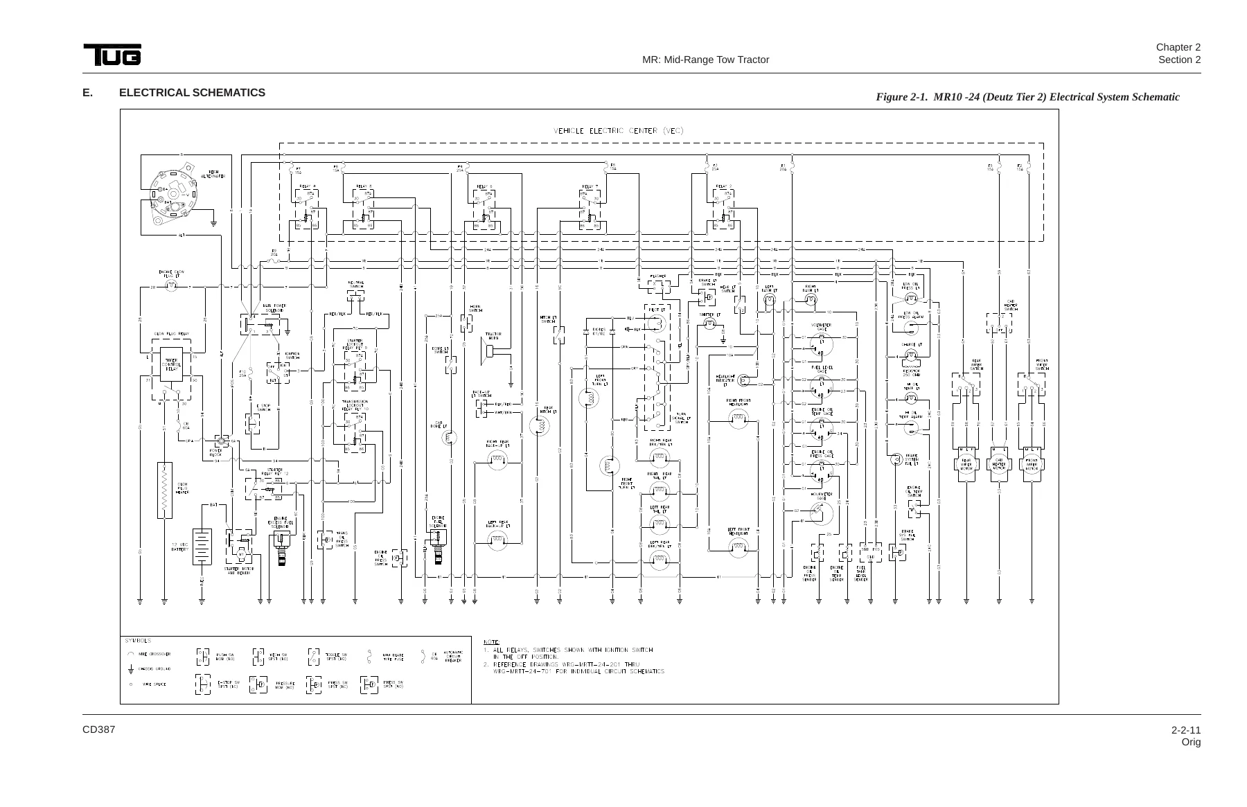
The troubleshooting section in Chapter 2 addresses real-world problems: tractor will not start, engine will not start below 60°F, loss of power or reduction in pulling power, inability to maintain engine operating temperature, rough ride, drive axle noise, vehicle pulling to one side, excessive stopping distance, front or rear brakes dragging or uneven pull, spongy brake pedal, hard pedal, parking brake not holding, exterior lighting faults, interior lighting faults, wiper motor faults, and horn faults. Each entry lists probable causes and remedies. The electrical system schematics for the MR10-24 (Deutz Tier 2), MR36 (Kubota), and MR10-34 (Deutz Tier 4i) provide complete circuit tracing. The hydraulic schematic covers the steering and hydro-boost brake system.
The removal and installation section of Chapter 2 is exceptionally thorough. It covers the cab, doors, door check straps, cab heater, door windows, front windshield, rear windshield, rear side windows, rear view mirror, side mirrors, mirror mounting brackets, front wiper motor, rear wiper motor, windshield wiper switches, hood panel, pintle hitches, seats, retractable seatbelts, battery, dash panel assembly, dash illumination lights, gauges, headlight switch, hitch light switch, heater switch, ignition switch, warning light assembly, light lenses, warning light bulbs, turn signal flasher unit, exterior lamp assemblies, headlight assembly, turn signal light assembly, brake/turn/stop light assembly, back-up light assembly, hitch light assembly, dome light lamp housing, emergency stop switch, electric center panel assembly, fuses, relays, power block, starter relay, 60 amp circuit breaker, starter-lockout relay, transmission lockout relay, glow plug relay, glow plug relay socket, main power solenoid, mini fuses, starter, low oil pressure and high oil temperature alarms, horn assembly, fuel system components, accelerator and modulator assembly, air intake assembly, cooling assembly, exhaust system, engine and engine components including Quick Engine Change procedures for Deutz Tier 2, Deutz Tier 4i, and Kubota, transmission assembly including C6 and 4R75, front axle, suspension, wheels, drive shaft, drive axle, rear wheel assembly, shock absorbers, brake system, parking brake assembly, and hydraulic power steering system.
Chapter 3 covers the front steer axle in detail: recommended overhaul periods for the engine, transmission, and steer axle, axle assembly inspection, removal and installation, king pin and knuckle service, front wheel bearing removal and installation, front leaf spring and shackle service, tie rod end service, and front wheel alignment procedures.
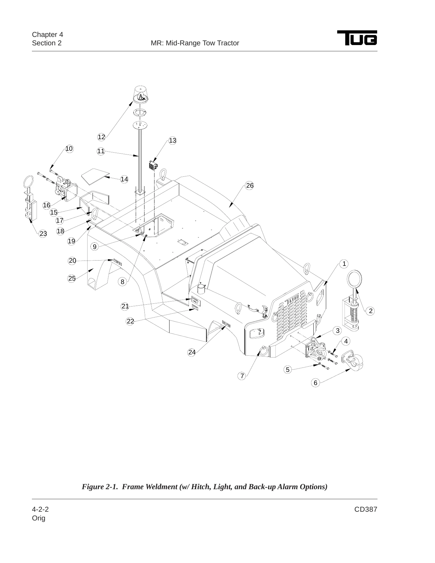
Chapter 4 is the illustrated parts list. It contains exploded-view figures with corresponding tables listing figure and index number, TUG part number, description, quantity, and effectivity. Major assemblies covered include the frame weldment with hitch, light, and back-up alarm options, access panels for Deutz Tier 2, Kubota, and Deutz Tier 4i, hood assembly, cab mounting, cab insulation, cab mirrors, cab door installation, driver and passenger door assemblies, cab windows, front and rear windshield wipers, exterior lamp assemblies, dome light, emergency stop switch assembly, lower dash access panel, seat installation, cab heater installation for Deutz and Kubota, dash assembly with harness for all three engine variants, console assembly for CE option, alarm assembly, brake pedal assembly, steering column assembly, hydraulic steering system for Deutz and Kubota, front suspension, front steer axle assembly, hub and rotor assembly, brake calipers assembly, rear suspension assembly, rear drive axle drain plugs, gear set and differential, planetary wheel end drive, wet brakes system, drop box drain plugs, front and rear wheel assemblies, accelerator and modulator cables for Deutz Tier 2 and Kubota, accelerator pedal for Deutz Tier 4i, engine and transmission mounts, engine installation for Deutz Tier 2, Deutz Tier 4i, and Kubota, engine assembly for Deutz Tier 2 and Deutz Tier 4i, front engine covers, alternator assembly, starter assembly, timing belt and PTO assemblies, hydraulic pump PTO drive assembly, oil pan installation, air intake assembly, fuel system, exhaust system, cooling system, transmission oil pan assembly, transmission filter screen and valve body, transmission band adjustment, shifter assembly, shifter linkage, park brake lever installation, transmission park brake assembly, engine and transmission assembly for Deutz Tier 4i and 4R75, transmission (4R75) assembly, transmission sensors installation, transmission oil pan installation (4R75), shifter assembly (4R75), park brake assembly (4R75), drive shaft assembly for C6 and 4R75, Deutz Tier 4i ECU and 4R75 TCU installation, VEC panel assembly, TEC panel assembly, brake line system, hydroboost installation, battery assembly, battery assembly with heater option, battery assembly for CE option, heater junction box, and horn installation. The numerical index lists every part number in ascending order with its figure and index reference. The alphabetical index lists every part by description.
In addition to the TUG-specific content, this PDF includes three complete supplementary manuals that are essential for anyone servicing the major components. The Deutz D/TD/TCD 2011 Engine Operation Manual covers engine description and illustrations, lubricating oil schematic, fuel schematic, coolant schematic, exhaust gas recirculation, electrics and electronics, operation including ambient conditions and initial commissioning, start procedure, operation monitoring, stop procedure, operating media including lubricating oil, fuel, and coolant specifications, maintenance schedule, care and maintenance work including lubricating oil system, fuel system, cooling system, engine cleaning, suction system, belt drives, setting work, and electrical system, fault table, engine management, transport and storage, and technical data including engine and setting data and tools. The Ford 4R70E/4R75E Automatic Transmission Manual covers general specifications, identification tags, range selection, shift patterns, torque demand, description and operation of the torque converter, planetary gearset, clutch and band apply components, accumulators, hydraulic system including fluid pump, filter, and main control, transmission electronic control system including sensors and actuators, diagnostic trouble code charts, pinpoint tests for shift and torque converter clutch solenoids, transmission fluid temperature sensor, digital transmission range sensor, electronic pressure control solenoid, output shaft speed sensor, turbine shaft speed sensor, solenoid mechanical failure, line pressure test, stall speed test, air pressure tests, clutch pressure test, leakage inspection, transmission fluid cooler flow test, diagnosis by symptom charts, disassembly, disassembly and assembly of subassemblies including main control valve body, pump and intermediate clutch piston, intermediate one-way clutch, reverse clutch, forward clutch cylinder, planetary gear support assembly and planetary one-way clutch, reverse sun gear, output shaft and direct clutch cylinder, assembly, installation, removal, and in-vehicle repair procedures. The Murphy PowerView Model PV-101-C User’s Guide covers engine and transmission parameters, faceplate features, navigation and keypad functions, first time start up, main menu options including DPF regen, selecting a language, stored codes, engine configuration, setup 1-up display, setup 4-up display, service reminders, select units, backlight adjustment, contrast adjustment, utilities menu including gage data, remove all gages, software version, fault conversion, analog input, engine speed control, OEM menu including MODBUS setup, CANBUS data rate, select engine ECU, set source address, restore all defaults, clear machine hours, set machine hours, clear fault codes, fuel setpoints, DPF regen menu on/off, ENG SPD CTRL menu on/off, faults and warnings including auxiliary gage fault, active fault codes, derate/shutdown codes, acknowledging fault codes, and troubleshooting.
This is not a generic collection of documents. The TUG MR Mid-Range Tow Tractor Operation, Maintenance & Parts Manual – CD387 is a single, integrated PDF that places the machine-specific procedures, the engine manual, the transmission manual, and the display user’s guide in one searchable, printable file. For fleet maintenance departments, ground support equipment shops, and individual technicians responsible for TUG MR tow tractors, this manual eliminates the need to hunt down separate publications for the tractor, the Deutz or Kubota engine, the Ford transmission, and the Murphy display. Every procedure, specification, torque value, fluid capacity, wiring diagram, hydraulic schematic, and part number needed to keep a TUG MR tractor in service is contained in this document.
Why This Manual Matters
Tow tractors in aviation ground support service operate under constant load, in all weather conditions, and often around expensive aircraft where a failure has consequences far beyond the tractor itself. The TUG MR is designed with a 12,500 lb gross vehicle weight, 83% of that on the rear drive wheels, and a towing capacity of 100,000 lbs forward and 80,000 lbs reverse. The braking system combines front disc brakes with rear hydraulic wet disc brakes having six discs per side. The steering is hydrostatic power-assisted with a 4 gpm flow-control vane pump and 1,000 psi relief valve. The transmission options are the Ford C-6 three-speed automatic and the Ford 4R75 electronic transmission. The engine options are the Deutz BF4M2011 at 88 horsepower and 199 ft-lbs peak torque, the Deutz TD2011 L040, and the Kubota V3600T at 84.5 horsepower and 218.3 ft-lbs peak torque, or the Kubota V3600 at 66.8 horsepower and 162 ft-lbs peak torque. Each of these systems has specific service requirements, fluid specifications, torque values, and adjustment procedures. The wrong brake fluid, the wrong transmission fluid, an incorrect band adjustment, a misadjusted neutral safety switch, or a neglected axle oil change can lead to premature failure, unscheduled downtime, and repair costs that dwarf the price of this manual.
The periodic maintenance schedule in this manual is not a suggestion; it is the manufacturer’s required service interval plan. Engine oil and filter must be changed at initial 200 hours and then every six months. Rear drive axle oil must be changed at initial 200 hours and then every year. Air filter element must be changed every six months. Fuel filter/water separator element must be changed yearly. Chassis lubrication and driveshaft U-joint lubrication must be performed every two years. The emergency stop switch must be tested every two years. Front and rear tire pressures must be checked regularly. Front wheel bearing free play must be checked every six months. Brake system hoses must be inspected yearly. The manual also specifies the exact fluid types: 15W-40 engine oil, Dexron III transmission fluid for the C-6, MERCON V for the 4R75, SAE 80-90LS (GL5) gear oil for the drive axle and drop box, Dexron III for the power steering and hydraulic system, DOT 3 brake fluid, and the correct diesel fuel specifications including ULSD, VV-F-800, JP5, and JP8. Using the wrong fluid is a common cause of premature failure, and the specifications in this manual are the authoritative source.
For those performing repairs, the removal and installation procedures are written with the level of detail that prevents damage and injury. The manual specifies when to use a hoist, when to support the transmission with a jack, when to use a safety observer, when to disconnect the battery negative cable first, when to discard lock nuts and lock washers and replace with new, when to apply thread sealant or Loctite, when to lubricate seals with petroleum jelly or clean transmission fluid, and when to torque fasteners to specific values. The torque specifications alone — 45 ft-lbs for transmission housing bolts, 30 ft-lbs for torque converter nuts, 22 ft-lbs for axle drain plugs, 50 ft-lbs for axle U-bolt lock nuts, 60 ft-lbs for driveshaft flange bolts, 125 ft-lbs for front lug nuts, 225 ft-lbs for rear lug nuts, 280 ft-lbs for pintle hitch bolts, 300 ft-lbs for axle mounting bolts, 40-45 ft-lbs for caliper mounting pins, 35 ft-lbs for hand brake lever bolts, 25 ft-lbs for steering column nut, 15 ft-lbs for spindle nut seating, 10 ft-lbs for transmission oil pan bolts — are the difference between a repair that lasts and a repair that fails. This manual provides them in the context of the procedure where they are needed.
The electrical schematics are another critical resource. The MR10-24 (Deutz Tier 2) and MR36 (Kubota) electrical system schematic and the MR10-34 (Deutz Tier 4i) TUG Electric Center schematic show every circuit, every connector, every relay, every fuse, and every ground point. The Vehicle Electrical Center (VEC) fuse panel diagram identifies fuse F1 through F8 and relay R1 through R8 by function. The TUG Electric Center (TEC) fuse panel diagram identifies fuse F1 through F12 and relay K5 through K8 by function. The Neutral Safety/Reverse Switch Wiring diagram shows the Deutsch DT06-6S connector pinout. The Turn Signal Switch Wiring diagram shows the Deutsch DT04-8P connector pinout. The Emergency Stop Switch wiring diagram shows the Deutsch DT06-2S connector pinout. For anyone tracing an electrical fault, these diagrams are indispensable and are often missing from used equipment sales.
The hydraulic schematic for the hydro-boost power brake and steering system shows the pump, relief valve, shut-off valve, reservoir, steer valve, steering cylinder, and hydro-boost unit with all connecting hoses identified by part number. This is the roadmap for diagnosing steering and brake assist problems.
For parts identification, the illustrated parts list contains every figure and index number, TUG part number, description, quantity, and effectivity. The numerical index at the end of Chapter 4 lists every part number in the manual in ascending order with its figure and index reference, so a technician who has a part number can find the exact diagram and location in seconds. The alphabetical index lists every part by description, so a technician who knows what the part is called can find the part number and figure reference. This dual-index system makes the parts list unusually fast to use.
IMAGES PREVIEW
Instant PDF Delivery
This TUG MR Mid-Range Tow Tractor Operation, Maintenance & Parts Manual is delivered as an instant PDF download immediately after payment. There is no shipping, no waiting, and no physical media to lose or damage. The file can be stored on a shop computer, a laptop, a tablet, or a smartphone, and printed pages can be taken directly to the machine. The PDF format allows zooming in on fine details in the exploded views, wiring schematics, and hydraulic diagrams. The manual can be searched for part numbers, model numbers, torque values, or procedure names. Whether you are performing a daily inspection, a 200-hour service, a major engine or transmission overhaul, or a brake system repair, this manual gives you the information you need in a format you can use immediately. For anyone responsible for a TUG MR tow tractor, this is the reference that makes every job faster, safer, and more accurate. Do not rely on memory, guesswork, or incomplete third-party documentation. Get the complete factory-issued CD387 manual and have the full scope of operation, maintenance, troubleshooting, and parts information at your fingertips.
Reviews
There are no reviews yet.